Embed Size (px)
Citation preview

1 Copyright © 2016 by ASME
Proceedings of ASME Turbo Expo 2016: Turbomachinery Technical Conference and Exposition GT2016
June 13 – 17, 2016, Seoul, South Korea
GT2016-56168
THE ROLE OF IMPELLER OUTFLOW CONDITIONS ON THE PERFORMANCE OF VANED DIFFUSERS
Jonathan Everitt*, Zoltán Spakovszky
Massachusetts Institute of Technology,
Cambridge, MA, USA
Daniel Rusch ABB Turbo Systems Ltd,
Baden, Switzerland
Jürg Schiffmann École Polytechnique Fédérale de
Lausanne, Lausanne, Switzerland
ABSTRACT Highly-loaded impellers, typically used in turbocharger
and gas turbine applications, exhaust an unsteady, transonic
flow that is non-uniform across the span and pitch and swirling
at angles approaching tangential. With the exception of the flow
angle, conflicting data exist regarding whether these attributes
have substantial influence on the performance of the
downstream diffuser.
This paper quantifies the relative importance of the flow
angle, Mach number, non-uniformity and unsteadiness on
diffuser performance, through diffuser experiments in a
compressor stage and in a rotating swirling flow test rig. This is
combined with steady and unsteady Reynolds-Averaged Navier
Stokes computations. The test article is a pressure ratio 5
turbocharger compressor with an airfoil vaned diffuser. The
swirling flow rig is able to generate rotor outflow conditions
representative of the compressor except for the periodic
pitchwise unsteadiness, and fits a 0.86 scale diffuser and volute.
In both rigs, the time-mean impeller outflow is mapped across a
diffuser pitch using miniaturized traversing probes developed
for the purpose.
Across approximately two-thirds of the stage operating
range, diffuser performance is well correlated to the average
impeller outflow angle when the metric used is effectiveness,
which describes the pressure recovery obtained relative to the
maximum possible given the average inflow angle, Mach
number and the vane exit metal angle. Utilizing effectiveness
captures density changes through the diffuser at higher Mach
numbers; a 10% increase in pressure recovery is observed as
the inlet Mach number is increased from 0.5 to 1. Further,
effectiveness is shown to be largely independent of the time-
averaged spanwise and unsteady pitchwise non-uniformity
from the rotor; this independence is reflective of the strong
mixing processes that occur in the diffuser inlet region. The
observed exception is for operating points with high time-
averaged vane incidence. Here, it is hypothesized that
temporary excursions into high-loss flow regimes cause a non-
linear increase in loss as large unsteady angle variations pass by
from the rotor.
Given that straight-channel diffuser design charts typically
used in preliminary radial vaned diffuser design capture neither
streamtube area changes from impeller exit to the diffuser
throat nor vane incidence effects, their utility is limited. An
alternative approach, utilizing effectiveness and vane leading
edge incidence, is proposed.
INTRODUCTION
Modern high pressure ratio centrifugal compressors
typically utilize a high speed impeller with backswept blades
and a vaned diffuser. As part of ongoing efforts for a system-
wide reduction in weight, increase in efficiency and/or
reduction of emissions, designers seek to improve the pressure
ratio, operating range and efficiency of the centrifugal
compressor, which is often limited by the diffuser. Despite the
relative simplicity of its geometry, the flow in the diffuser is
complex and there is no well-established, reliable approach to
guide design for these goals.
For the purposes of preliminary design of vaned diffusers,
the flow is frequently approximated as two-dimensional: either
that of straight-channel, quasi-1D diffusers (allowing use of
diffuser design charts such as those by Reneau [1]) or
geometrically transformed cascade airfoils (e.g. [2]). This is
despite their apparent limitations; various techniques must be
employed to correct for the clear differences in geometry as
well as for the effects of incidence on to the diffuser vanes.
Additionally, the empirical data shows insensitivity to Mach
number, in conflict with the expected results from quasi-1D
flow theory, and a strong dependence on throat blockage, which
is difficult to quantify (or avoid) in centrifugal compressor
* Current address: Altaeros Energies Inc., 28 Dane St., Somerville, MA, 02143

2 Copyright © 2016 by ASME
diffusers. As a consequence, the usefulness of these approaches
is questionable; for example, using cascade airfoil data severely
underestimates loss [2].
In a two-part paper, Filipenco and Deniz et al. [3,4] argue
that radial vaned diffuser pressure recovery performance
correlate uniquely to the momentum averaged inflow angle, as
long as the pressure recovery coefficient is defined using the
“availability average” inflow total pressure. This method of
averaging best captures the relevant flow quantities for the
diffuser, and under most flow conditions is very similar to the
mass flow average [5]. Given this correlation has no direct
dependence on blockage, they suggest that designing for low
blockage at diffuser inlet has no advantage, providing that the
diffuser is designed to operate at an appropriate mean inflow
angle. The conclusion is based on data taken for high solidity
diffusers in a swirling flow test rig, using inflow parameters
determined to be representative of high pressure ratio gas
turbine engine centrifugal compressors. Their generality to real
compressors, or to different diffuser geometries, is unclear.
When applied to the diffuser studied in this paper, the
correlation of pressure recovery to the momentum-averaged
flow angle is significantly worse than observed by Filipenco or
Deniz, as indicated in Figure 1 (scales are removed to protect
proprietary data). Here the pressure recovery coefficient across
the diffuser, defined as:
𝐶𝑝 = 𝑝5−𝑝2𝑎
�̅�𝑡,2𝑎𝑚 −𝑝2𝑎
(1)
is plotted against the momentum averaged inflow angle, such
that left-to-right represents a compressor speedline throttled in
to stall. The spread in 𝐶𝑝 at the penultimate operating point
before stall is 18%. The derivation of this experimental data is
described later in the paper.
Figure 1: Experimentally determined pressure recovery coefficient
𝑪𝒑 for the research diffuser, as a function of momentum averaged
angle as defined by Filipenco et al. [3] showing relatively poor
correlation.
In contrast to Filipenco and Deniz, who determined that the
non-uniformity in the spanwise direction had little impact on
the diffuser pressure recovery performance, Spakovszky and
Roduner [6] demonstrate that both pressure recovery and stable
flow range can be highly sensitive to flow leakage at impeller
exit. The pre-production compressor investigated in that paper
is of aggressive design, pushing the limits in stage matching.
The leakage flow, used for thrust balance and bearing
compartment sealing, is suggested to have a profound effect on
component matching with changes in one-dimensional
corrected flow overriding any potential effects of spanwise flow
non-uniformity.
The unsteady impeller outflow has been characterized
using URANS simulations or PIV/LDV by several researchers
e.g. [7-10]. It is generally agreed that the effects of this
unsteady flow on diffuser performance are limited at design
conditions. However, little data exists at off-design conditions.
Baghdadi [11] compared diffuser performance within a
stationary swirling flow rig to a compressor rig and determined
differences were small, but inflow measurements were limited.
Clear design guidelines arising from these studies are lacking,
and it is evident that unsteady CFD remains too
computationally expensive, both in solution time and post-
processing, to be part of the routine design cycle.
SCOPE OF PAPER The goal of this paper is to quantify the relative
significance of different flow features present in the inflow of
radial vaned diffusers, in terms of their influence on steady-
state diffuser performance (pressure recovery and loss). These
flow features are the average inflow angle and Mach number,
the time-averaged spanwise flow non-uniformity (or blockage),
and the unsteady pitchwise flow non-uniformity. At the outset
of the project, the following hypotheses were postulated: (a) the
unsteadiness of the diffuser inflow, caused by the pitchwise
non-uniformity imposed by the rotating impeller upstream, has
negligible influence on the diffuser aerodynamics, consistent
with the prevailing consensus in the literature [12]; (b) the
spanwise flow non-uniformity, considered in a time-averaged
sense, impacts the flow aerodynamics in the diffuser inlet
region (inlet to diffuser throat) and hence the overall diffuser
performance and stall characteristics; and (c) that the effects of
Mach number should be measurable in the performance of the
diffuser.
The approach taken combines a series of experiments in
two experimental facilities. Unique to this research,
comprehensive data has been taken on a swirling flow test rig
together with a compressor test bed, using the same radial
vaned diffuser as a test article. This allows the influence of the
diffuser inflow features to be isolated in the steady state
diffuser performance. In addition, this data are supported by
computational simulations using steady and unsteady RANS,
allowing additional interrogation of the flow features.
This work indicates incidence onto the diffuser vanes is a
primary driver of diffuser performance, with greater sensitivity
as Mach numbers increase. The time-average spanwise non-
uniformity into the diffuser has little impact on the diffuser
performance except as it affects the mixed out average
conditions. Additionally, unsteadiness arising from the

3 Copyright © 2016 by ASME
upstream impeller has the greatest effect on the diffuser at off-
design conditions, where it is proposed that large temporal flow
angle variations give rise to worse performance due to the
highly non-linear relationship between loss and incidence. For a
large proportion of the operating range, it is shown to have little
impact. The work develops, and then uses, a compressible
definition of diffuser effectiveness as a performance metric,
using a mixed-out condition as a means of characterizing the
diffuser inflow.1
NOMENCLATURE
𝐴 Area 𝐴𝑒𝑓𝑓 Effective area
𝑏 Passage height / span bpf Blade passing frequency 𝑐𝑝 Specific heat at constant pressure
𝐶𝑝 Static pressure recovery coefficient
𝐶𝑝,𝑡 Total pressure loss coefficient
CFD Computational Fluid Dynamics CH Near choke operating point
𝐷(𝑀) Compressible flow function �̇�√𝑐𝑝𝑇𝑡
𝐴𝑝𝑡
�̇� Mass flow
𝑀 Mach number
𝑝 Static pressure 𝑝𝑡 Total pressure �̅�𝑡
𝑚 Mass averaged total pressure 𝑟 Radius
𝑅𝑒 Diffuser Reynolds number 𝜌2𝑎𝑢2𝑎𝑏2𝑎
𝜇2𝑎
ST Near stall operating point 𝑇𝑡 Total temperature 𝑢 Flow velocity [U]RANS [Unsteady] Reynolds Averaged Navier Stokes 𝑧 Axial coordinate (spanwise at diffuser inlet) 𝛼 Flow angle, from radial 𝛾 Ratio of specific heats
𝜂𝑚𝑎𝑥 Near maximum efficiency operating point
𝜃 Circumferential coordinate (pitchwise at diffuser inlet)
𝜌 Density 𝜒 Blade metal angle, from radial
Ω Impeller rotational speed Compressor stations 1 Impeller leading edge axial plane 2 Impeller trailing edge radius 2a Diffuser inlet measurement plane
1 A note on figures: The paper introduces plots with relatively unfamiliar
ordinates of flow angle and incidence. Our convention is that flow angles are measured from radially outward, with positive being in the direction of impeller
rotation. With these ordinates, the positive direction (left to right) is in the
direction from choke to stall. Scales are typically removed because the data are from current production turbocharger compressors and are proprietary.
3 Diffuser leading edge radius 3a Diffuser throat 4 Diffuser trailing edge radius 5 Diffuser exit measurement radius 6 Volute exit D/S VLS Vaneless space downsteam of vaned diffuser (4-5) SVLS Semi-vaneless space (approx. 3-3a) U/S VLS Vaneless space upsteam of vaned diffuser (2a-3) TECHNICAL ROADMAP
For this research, we primarily consider one, “datum”
diffuser geometry: a radial diffuser from a large turbocharger
compressor with 17 airfoil shaped vanes (see Figure 2). This is
the geometry that is tested back-to-back in the compressor and
the swirl rig. Additionally, two further airfoil vaned diffusers
are studied numerically. These featured differing inlet stagger,
as such defining different diffuser leading edge angles and
throat areas (see Figure 2). This can have significant impact on
stage performance due to the effect on impeller/diffuser
matching, as discussed in [13], and is therefore of interest for
this study.
Figure 2: Project diffusers showing how the camber line is altered
to vary the throat area. This modifies the leading edge angle. The
trailing edge angle is invariant for volute matching. “D” is short
for “diffuser” and D2 is the datum geometry.
The datum diffuser is first tested on a compressor test bed,
with a stage design stagnation pressure ratio of 5. The diffuser
inflow is measured through two specially designed, miniature
traversing probes used in the diffuser inlet region. One probe
measures total pressure and flow direction across the span at
each pitchwise location, while the second records the spanwise
variation in total temperature. Four circumferential (pitchwise)
positions are measured across one diffuser vane pitch for each
operating point (see Figure 4).
A 0.86 scale replica of the diffuser is then tested within the
swirling flow test rig. Here, inlet conditions can be replicated
from the compressor test facility in terms of average inflow
angle and Mach number. The rig features bleed slots at the
diffuser inlet that can be used for suction or injection, allowing
the time-averaged spanwise flow profiles from the compressor
to be approximately replicated within the test rig. However, the
unsteady, pitchwise flow non-uniformity imposed by the rotor
is different.
The Reynolds number and reduced frequency (defined by
the relative timescales of rotor blade passing and the mean
throughflow time of the diffuser flow) overlap between the two
D1
D2
D3
4 Copyright © 2016 by ASME
facilities. Table 1 provides a summary of the relevant non-
dimensional parameters and flow conditions.
The time-averaged spanwise non-uniformity, together with
the time- and spatially averaged inflow angle and Mach
number, can be closely matched between the two rigs. This
allows the effects of the unsteady pitchwise inflow non-
uniformity to be isolated, when comparing the performance of
the datum diffuser between the two rigs.
Compressor Swirl rig
Scale factor 100% 86%
Re 2×10⁵ – 5×10⁵ 1.2×10⁵ – 3×10⁵
Reduced frequency (bpf)
14 – 15 1.3 – 24
Maximum Mach number
1.2 1.2
Maximum flow angle (from radial)
75° 75°
Flow angle distribution
Up to 35° Match via control slots
Mach distribution Continuously varies from 0 – 1.2 across span
Match via control slots
Exit conditions Volute Volute
Table 1: Comparison of swirling flow rig and compressor rig
Characterizing the influence of the spanwise inflow non-
uniformity is more challenging, since it must be isolated from
other effects such as averaged inflow angle or Mach number, or
pitchwise non-uniformity. To identify ‘similar’ inflow
conditions with differing distributions of Mach number and
flow angle, appropriate spatial averages must be defined. With
these averaged values, every operating point in either the
compressor or the swirl rig exhibits different time-averaged
spanwise profiles.
For further differences in spanwise profile, two other
impeller geometries are studied numerically. These are also
production turbocharger compressor impellers with
approximately the same stage total pressure ratio. However,
they are not of evolutionary design but rather are developed
independently, and include differing features such as blade
count (8 or 9 main blades plus splitters), endwall profiles,
trailing edge spans, and twist at the trailing edge, providing a
range of different impeller outflows (further discussed below).
Table 2 shows the complete matrix of geometries examined in
this project.
Impeller 1 Impeller 2 Impeller 3
Diffuser 1 CFD only
Diffuser 2 CFD only DATUM CFD
Compressor rig Swirl rig
CFD only
Diffuser 3 CFD only
Table 2: Matrix of compressor geometries.
EXPERIMENTAL FACILITIES The MIT swirling flow diffuser test facility utilized (the
“swirl rig”) comprises a high-solidity, forward leaning, radial
rotor, which can provide a highly swirling, transonic flow for
the downstream diffuser. The rotor design aims to minimize the
pitchwise variations from the rotor by using 72 negative
reaction rotor blades, with the relative velocity continuously
rising and the static pressure continuously dropping through the
rotor. The design is a modification of that used by Filipenco,
described in [3, 14]. Details of the modifications can be found
in [15]; these included modification of span-to-radius ratio and
the fitting of a turbocharger volute.
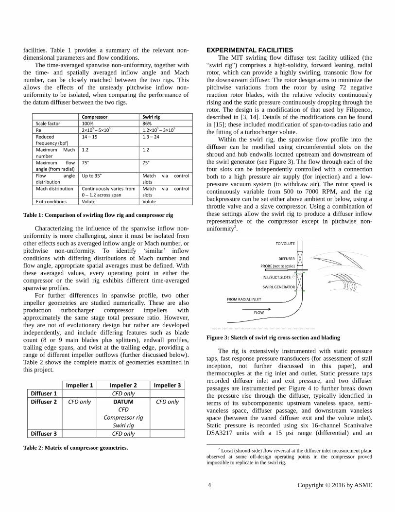
Within the swirl rig, the spanwise flow profile into the
diffuser can be modified using circumferential slots on the
shroud and hub endwalls located upstream and downstream of
the swirl generator (see Figure 3). The flow through each of the
four slots can be independently controlled with a connection
both to a high pressure air supply (for injection) and a low-
pressure vacuum system (to withdraw air). The rotor speed is
continuously variable from 500 to 7000 RPM, and the rig
backpressure can be set either above ambient or below, using a
throttle valve and a slave compressor. Using a combination of
these settings allow the swirl rig to produce a diffuser inflow
representative of the compressor except in pitchwise non-
uniformity2.
Figure 3: Sketch of swirl rig cross-section and blading
The rig is extensively instrumented with static pressure
taps, fast response pressure transducers (for assessment of stall
inception, not further discussed in this paper), and
thermocouples at the rig inlet and outlet. Static pressure taps
recorded diffuser inlet and exit pressure, and two diffuser
passages are instrumented per Figure 4 to further break down
the pressure rise through the diffuser, typically identified in
terms of its subcomponents: upstream vaneless space, semi-
vaneless space, diffuser passage, and downstream vaneless
space (between the vaned diffuser exit and the volute inlet).
Static pressure is recorded using six 16-channel Scanivalve
DSA3217 units with a 15 psi range (differential) and an
2 Local (shroud-side) flow reversal at the diffuser inlet measurement plane
observed at some off-design operating points in the compressor proved impossible to replicate in the swirl rig.

5 Copyright © 2016 by ASME
accuracy of 0.05% full scale. A calibrated venturi in the exit
duct is used for mass flow measurement.
In addition, miniature traversing probes were developed for
measurement of the time-average spanwise total pressure, flow
angle, and total temperature. In the swirl rig, only the total
pressure/angle (𝑝𝑡/𝛼) probe is used, and the total temperature,
measured at the volute exit, is assumed uniform across the
span3. The probe comprises a 0.8 mm closed tube which spans
the diffuser for the entire traverse. A single 0.1 mm hole is
drilled perpendicular to the tube axis on one side, and a
pressure transducer is close-mounted inside the probe, just
outside the diffuser plate, to record the pressure.
Figure 4: Static pressure taps within a diffuser passage used to
break down pressure recovery into subcomponents, together with
traverse probe locations A-D (shown in adjacent passage only for
illustration).
The 𝑝𝑡/𝛼 probe can be mounted in four different
circumferential positions equally spaced across one pitch, thus
each operating point is repeated four times for the complete
diffuser inflow mapping. Since the probe frequency response is
typically less than the rotor blade passing frequency, the
pitchwise non-uniformity measured is only that caused by the
upstream pressure field of the diffuser vanes. At each
circumferential position, the probe is moved axially through the
diffuser in a number of steps, clustered near the endwalls. At
each axial position, the probe is rotated about its principal axis
in steps of 15°. The measurements thus taken are subsequently
post-processed, in combination with the endwall static pressure
measurements, to map the total pressure and the flow angle
profiles into the diffuser. The probe accuracy for angle
measurement is estimated through controlled wind tunnel tested
as ±0.5°.
A second probe was developed to measure spanwise
variations in total temperature, but this is only used in the
compressor rig, where total temperature varies significantly
across the span. This total temperature (𝑇𝑡) probe comprises a
0.81 mm tube with two aligned holes drilled radially through
the tube. The first hole, 0.46 mm in diameter, is rotated to face
3 The work done by the swirl rig rotor is low, resulting in total temperature
ratios below 1.15. The assumption of uniform total temperature is fair.
the direction of the flow (the probe is used following a traverse
of the total pressure and flow angle probe). Flow approaching
the probe is brought to rest at the thermocouple head and vents
through the downwind hole, which is 0.15 mm in diameter.
Within the tube a miniature K-type thermocouple is mounted
with the exposed bead held between the two holes. The 𝑇𝑡
probe is calibrated for temperature recovery factor per [16].
Further information on both traversing probes and their
calibration can be found in [15].
The Super-Martin (SUMA) closed loop compressor test
facility at ABB Turbo Systems Ltd. in Baden, Switzerland is
used for the compressor tests. The compressor has a high
swallowing capacity, open impeller, with a design impeller
blade Mach number, 𝑀2 = Ω𝑟2/√(𝛾𝑅𝑇𝑡1), of 1.54 and with 9
backswept and splittered blades. It is electrically driven. The
gas circuit contains a water-cooled heat exchanger such that the
inlet conditions can be maintained with constant total
temperature to within approximately ±1K. The inlet total
pressure can also be reduced to sub-ambient to allow operation
of the rig at high pressure ratios without excessive power
requirements by reducing the inlet air density.
The diffuser is instrumented, as far as possible, identically
to the diffuser tested in the swirl rig; however static pressure
measurements are taken using ABB’s standard data acquisition
system, compliant with ISO9001. In addition to the diffuser
instrumentation described above, the compressor rig includes
multi-point static pressure and temperature measurement in the
ducts upstream and downstream of the compressor, and a v-
cone to measure mass flow. These data are post-processed with
a proprietary meanline data reduction scheme to calculate
conditions through the compressor. The maximum
measurement errors, to within 95% confidence levels, are ≤
±1.0% for volume flow, ≤ ±0.2% for total pressure ratio and ≤
±0.5% for efficiency over the operating range considered
within this paper.
The radial spacing between the rotor trailing edge and the
diffuser leading edge is 15% of the rotor tip diameter in both
the swirl rig and the compressor rig. The diffuser inlet
conditions are recorded at a measurement plane which is
midway between the rotor and the diffuser. Both endwall static
pressure measurement and the traversing probes record data at
this radial location.
COMPUTATIONAL APPROACH Computations are all undertaken using the commercial
Reynolds-Averaged Navier Stokes (RANS) CFD code Numeca
FINE/Turbo, using a structured hexahedral grid generated with
the Numeca tool Autogrid. Unless otherwise noted, the
simulations are single-passage, ‘phase-lagged’ unsteady
simulations [17,18] with a computational domain which
includes both a single compressor impeller passage (main and
splitter blade) and a single diffuser passage.
Grid and timestep convergence studies were undertaken to
achieve acceptable accuracy while maintaining manageable
convergence times.. This results in a mesh containing 1.4
million cells for the impeller and 0.4 million cells in the

6 Copyright © 2016 by ASME
diffuser, and a timestep equivalent to 1/36th of the time taken
for a main blade to pass by one diffuser pitch.
The Spalart-Allmaras turbulence model is used following
successful application in past work [19]. According to best
practice, y+ ranges from 1-10 for the first cell off the wall.
Unless otherwise specified, the inlet conditions for the stage
calculations are defined as uniform and at ambient total
conditions i.e. 25°C and 1.03 bar, with an axial velocity vector
(i.e. normal to the stage inlet surface). The exit boundary
condition enforces a uniform static pressure at diffuser exit.
Further details on the numerical approach can be found in [15].
The agreement between computation and measurement,
and hence the accuracy of the former, is assessed through
evaluation of the stage total pressure ratio and efficiency,
impeller outflow average total pressure and flow angle,
impeller outflow spanwise profiles (see Figures 5 and 6), the
diffuser static pressure rise coefficient (together with its
subcomponents, see Figures 7 and 8), and the diffuser total
pressure loss coefficient. Only a sample of this data is shown
here; further validation is shown in [15].
Figure 5: Spanwise profiles of Mach number and radial
component at the diffuser inlet, at mid-pitch, as measured in the
compressor versus URANS.
Figure 6: Spanwise profiles of flow angle at the diffuser inlet, at
mid-pitch, as measured in the compressor versus URANS.
Figures 5 and 6 show the good agreement in spanwise
profiles observed: the maximum angle difference between
experiment and URANS is 5° and the maximum Mach
discrepancy is 11%. Similar agreement is obtained across the
different pitchwise positions and operating points; the worst
agreement is at 100% design speed case in choke, where an
angle error of 7° and a Mach error of 30% (in one localized
area) occurs.
The static pressure rise through the diffuser is reasonably
well estimated within the CFD; neglecting operating points in
or near choke, the agreement is within ±7%. Better results are
obtained at low compressor speed and toward stall, both of
which are indicative of lower diffuser Mach numbers. The
results also indicate the challenge in obtaining converging
solutions near to stall for the high speed cases.
Figure 7: Comparison of diffuser sub-component characteristics
recorded in the compressor tests (“Comp.”) and calculated in
URANS at 58% design corrected speed
Figure 8: Comparison of diffuser sub-component characteristics
recorded in the compressor tests (“Comp.”) and calculated in
URANS at 100% design corrected speed
At low inflow angles near the choke condition (left side in
Figures 7 and 8), the diffuser vane suffers negative incidence
stall. This is particularly noticeable in the simulations at 58%
design corrected speed, where the URANS simulations show
separated flow from the leading edge of the diffuser through the
entire diffuser passage. Separation, and the subsequent
separated flow, is typically not well captured in RANS
modeling [20]. Since large separations are present for all
speedlines at the lowest flow angle simulated, the inaccuracy in
the modeling of the separated flow is likely the cause for the
differences between experiment and the URANS results.
Additionally, shock waves that develop within the diffuser may
not be well captured with the relatively coarse mesh utilized for
the unsteady CFD. Supporting this hypothesis, it can be
(a) 58% speed, 𝜼𝒎𝒂𝒙 (b) 100% speed, 𝜼𝒎𝒂𝒙
(a) 58% speed, 𝜼𝒎𝒂𝒙 (b) 100% speed, 𝜼𝒎𝒂𝒙

7 Copyright © 2016 by ASME
observed that the diffuser channel, with the largest extent of
flow separation, is the subcomponent which shows the largest
discrepancy.
AVERAGING AND PERFORMANCE METRICS The typical metric for diffuser performance is the pressure
recovery coefficient, 𝐶𝑝, which is defined as the static pressure
rise 𝑝5 − 𝑝2𝑎 as a fraction of the inlet dynamic pressure,
𝑝𝑡2𝑎 − 𝑝2𝑎 [2,12]. The limitations of this definition, when used
for a radial vaned diffuser, are that (a) the diffuser pressure
recovery can depend on Mach number, due to density changes
through the diffuser; (b) it takes no account of the change in the
effective diffuser area ratio as the flow into the diffuser
becomes more tangential, which has the effect of reducing the
streamtube area into the diffuser and thus the contraction or
expansion of the flow from the impeller trailing edge to the
diffuser throat.
An alternative metric is the diffuser effectiveness [21],
which is the ratio of the diffuser static pressure rise to that of an
ideal, quasi-one-dimensional, diffuser. This is developed for the
application of radial compressors with compressible, non-
uniform, swirling inflow as follows:
It is assumed that the ideal area ratio of the diffuser is
defined by Equation 2:
𝐴𝑅 =𝐴5,𝑒𝑓𝑓
𝐴2,𝑒𝑓𝑓=
𝑟5
𝑟2𝑎
𝑏5
𝑏2𝑎
cos 𝜒4
cos 𝛼2𝑎 (2)
This is the “ideal” streamtube through the diffuser, defined
using the measured average diffuser inflow angle and the
diffuser vane trailing edge angle (i.e. the Kutta condition
applied to the diffuser vane and assuming flow angles do not
change significantly between the trailing edge and the diffuser
exit, which is a good assumption for the low Mach number
typically encountered downstream of the vaned portion).
For the ideal case, the inlet Mach number and flow angle
are taken as their average values and the flow is quasi-steady,
such that any 𝜕/𝜕𝑡 terms can be neglected.
The area ratio (Equation 2) allows the ideal exit Mach
number, 𝑀5,𝑖, to be calculated using the compressible flow
function 𝐷(𝑀) as in Equation 3:
𝐷(𝑀5,𝑖) =𝛾
√𝛾−1𝑀5,𝑖 (1 +
𝛾−1
2𝑀5,𝑖
2 )−
𝛾+1
2(𝛾−1)=
𝐷(𝑀2𝑎)
𝐴𝑅 (3)
Using the ideal exit Mach number, and setting total
pressure losses to be zero, it is possible to determine an ideal
pressure rise for the diffuser for any inlet Mach number and
flow angle using the isentropic relationship 𝑝
𝑝𝑡= 𝑓(𝑀).
The second diffuser performance metric used is the total
pressure loss coefficient 𝐶𝑝,𝑡. This is defined as the total
pressure reduction 𝑝𝑡,2𝑎 − 𝑝𝑡,5 as a fraction of the inlet dynamic
pressure. This represents the losses (or entropy gain) through
the diffuser.
The remaining performance metric for the diffuser, for
fully characterization, is the remaining kinetic energy in the
flow at its outlet. However it is possible to derive this from the
other two metrics, for a diffuser operating with ideal gas.
The average inflow Mach number and flow angles used
within the performance metrics are taken to be the mixed out
average [2,5,22]. This is further discussed in the following
section. For calculating the total pressure loss coefficient and
the dynamic pressure at diffuser inlet, the average total pressure
is taken as the mass average; the “correct” choice is the entropy
or availability average, but the mass average is more readily
measured and is typically similar [3,5].
EFFECT OF TIME-AVERAGE MACH NUMBER AND FLOW ANGLE
Rather than examine pitchwise non-uniformity first, it is
informative to assume that it has no impact on diffuser
performance then challenge that assumption later. This provides
insight that clarifies the later discussion.
Ten operating points are studied in the compressor tests:
near choke (CH), near stall (ST) and near best efficiency
(𝜂𝑚𝑎𝑥), for three different design corrected speeds. Diffuser
pressure recovery and effectiveness are calculated, as are
average inflow parameters such as the momentum average flow
angle, the mixed out average flow angle, and the average Mach
number. The correlation proposed by Filipenco [3] is tested
with this diffuser, but is found to suffer from a large spread as
previously shown in Figure 1; 17.7% variation in pressure
recovery is experienced within a momentum averaged angle
difference within one degree, around the 𝜂𝑚𝑎𝑥 operating point.
Figure 9: Results from the compressor test, showing diffuser
effectiveness correlates well with mixed out average flow angle.
Figure 9 shows that the data collapses if effectiveness is
used as the performance metric, and the mixed out average
angle as the correlating function. The exceptions are the CH
operating points. The use of different speeds in the compressor
means that a range of different inflows in terms of Mach
number, non-uniformity and unsteadiness are encountered. It is
found that the use of the mixed out average resolves issues of
different non-uniformities and unsteadiness, and that using

8 Copyright © 2016 by ASME
effectiveness improves the correlation of results at significantly
different Mach numbers. At low flow angles (CH operating
points), the data is scattered, and this is discussed later.
To further test the correlation, the results from the CFD
simulations are added to the plot in Figure 10. Here, all three
impeller geometries (I1, I2 and I3) are matched with the same
diffuser. Figure 11 shows a sample of the computed spanwise
profiles which are used. The CFD data further support the
correlation, with the same exception as observed earlier for the
cases with low average diffuser inflow angles.
Figure 10: Results from URANS simulations added to the results
from the compressor tests ("Comp"), at three different
compressor design corrected speeds
Figure 11: Spanwise profiles of flow angle at mid-pitch for three
URANS cases at the same mixed out average angle, showing a
variety of blockage and skew which obtain comparable pressure
recoveries
As observed by Filipenco and Deniz [3,4], the emphasis
placed on blockage in typical approaches to the analysis of
vaned diffusers appears misplaced. Mixing occurs through the
vaneless space between impeller and diffuser; CFD data shows
that, for the peak efficiency point at the design corrected speed,
the non-uniformity in mass flux reduces by 7% from impeller
trailing edge to the diffuser trailing edge. This contrasts with a
steady, non-mixing flow through a diffuser, where flow non-
uniformity worsens, causing poor pressure recovery and
potential flow reversal (see, for example, [22]).
The total pressure losses shown in Figures 12 and 13 take
the form of familiar loss buckets from cascade airfoil tests, with
the region of minimum loss narrowing with increased Mach
number. Minimum loss occurs at a small positive incidence,
and loss increases rapidly with reducing incidence (i.e. negative
incidences). This is due to a large region of separated flow on
the pressure side of the diffuser vane. On the side of positive
incidence, rather than showing increased loss (the right-hand
side of the bucket), instead the compressor stalls (or CFD
simulations fail to converge, which is taken as a crude proxy for
compressor instability). Between, there is a flat region of
minimum loss.
Figure 12: Total pressure loss coefficient (𝑪𝒑,𝒕) as a function of
diffuser inlet incidence, showing a classic ‘loss bucket’ shape
similar to cascade airfoil data; diffuser inflow Mach numbers >0.8,
and impeller/diffuser combinations as indicated by the legend.
Figure 13: 𝑪𝒑,𝒕 as a function of diffuser inlet incidence for diffuser
inflow Mach numbers from 0.5 to 0.8, showing greater sensitivity
to secondary effects such as diffuser loading distribution.
The rapid increase in loss, caused by separation at negative
incidence, is the cause for the rapid degradation of effectiveness
at low angles shown in Figure 10. The correlation at high Mach
number across all the diffuser geometries supports the

9 Copyright © 2016 by ASME
hypothesis that the loss is driven by incidence (rather than, for
example, purely the flow angle), since the different diffusers
have different leading edge angles. At lower speeds, other
sources of loss become relatively more important; examples
include the greater flow path or longer chord (and hence wetted
diffuser surface) for diffuser 1 relative to diffuser 3, which are
byproducts of the different camber, or the differences in loading
distribution, since diffuser 1 tends to be more aft-loaded.
Subsequent work has further explored this topic [23].
For both Figures 12 and 13, only CFD data are shown. The
exit total pressure is not recorded in experiments until
downstream of the volute. As such it is not possible to isolate
diffuser loss from volute losses. Trends between experiment
and CFD data are similar, as can be observed later in Figure 19,
except for an offset which is proportional to the kinetic energy
of the diffuser exit flow. Matching with the volute is discussed
in [12] and [23].
To return to the original hypotheses, the data does not
support that the spanwise flow profile has much impact on the
performance of the diffuser, except as it affects the mixed out
average conditions. This supports the general findings of
Filipenco and Deniz [3,4], although the mixed out average
angle is determined to be more generally applicable than the
momentum averaged angle used by these two authors. Taken in
combination with their data, three very different diffuser
geometries are tested (a pipe diffuser, a wedge-vaned channel
diffuser, and a relatively low solidity, airfoil vaned diffuser),
suggesting generality to the result. However, each has a
vaneless space 10% of the impeller tip radius or greater, which
may allow for greater mixing than a more close-coupled
compressor.
Additionally, the data reveals a consistent, measureable
impact of Mach number on the pressure recovery, counter to the
conclusion of some other researchers, for example [4]. The
impact is small, approximately a difference of 10% in pressure
recovery for Mach numbers varying from 0.5 to 1.0. It can be
quantified using a quasi-one-dimensional analysis of the
diffuser, using the assumption of a mixed out state at diffuser
inlet.
EFFECTS OF PITCHWISE NON-UNIFORMITY Data from the swirl rig indicate that the diffuser
effectiveness and total pressure loss remains well correlated to
the mixed out average angle. The diffuser performance is very
similar between the compressor tests and the swirl rig tests,
except as the compressor approaches high flow angles4. Here,
diffuser effectiveness is greater in the swirl rig, as shown in
Figure 14, which can be related to a higher total pressure loss in
the compressor, as shown in Figure 15.
To isolate the cause of this discrepancy, an operating point
representative of the 58% design corrected speed, near stall
point in the compressor is reproduced as closely as possible
within the swirl rig. This is achieved through careful adjustment
4 The high forward lean in the swirl generator meant that it is not possible
to achieve low flow angles.
of the rotor speed and volute backpressure, together with
application of cross-flow suction and injection through the
endwall slots upstream of the diffuser section. The mixed out
average inflow angle and Mach number agree to within less
than 0.1° and 4% respectively (the Mach number being lower in
the swirl rig). Comparing the spanwise flow profiles between
the compressor and the swirl rig for this operating point in
Figure 16, the agreement is qualitatively good.
Figure 14: Diffuser effectiveness in the compressor tests (“Comp.”)
and the swirl rig, showing generally good correlation. An
exception is where the swirl rig rotor is choked, leading to
supersonic diffuser inlet flow (“SS”).
Figure 15: Diffuser and volute 𝑪𝒑,𝒕 in the compressor tests
(“Comp.”) and the swirl rig. A clear difference exists between the
two machines at high angles.
The diffuser effectiveness and total pressure loss
coefficient measured in the swirl rig with this matched
condition are 0.06 higher and 0.05 lower respectively than that
measured in the compressor. This is shown in Figures 14 and 15
using a solid symbol; all other data points have no injection or
suction present. The estimated experimental errors in flow
angle, effectiveness, and total pressure loss coefficient (once
the uncertainty from the instrumentation is propagated through
the post-processing calculations) are ±0.6°, ±0.013, and ±0.003

10 Copyright © 2016 by ASME
respectively. The differences are clearly larger than can be
explained due to these errors.
The reduced frequency in the two tests (defined as the
diffuser through-flow time relative to a blade passing period) is
8% different. The Reynolds number is 42% lower in the swirl
rig; while this is a significant difference, the higher Reynolds
number in the compressor suggests lower loss (by
approximately 9%, according to the method of Strub et al. [24])
rather than the opposite as observed.
Figure 16: Spanwise profiles of flow angle (top) and Mach number
including radial component (bottom), for a matched operating
point representative of the compressor 58% speed, 𝜼𝒎𝒂𝒙 operating
point. “A” and “C” represent pitchwise positions per Figure 4.
We posit that the only major difference between the two
tests is in the magnitude of the unsteady pitchwise non-
uniformity from the rotor. It is proposed that the compressor
has a higher loss than the swirl rig at high angles due to the
unsteady fluctuation of incidence and the non-linearity of the
loss curve at high angles. At 58% design corrected speed, near
stall, RANS simulations5 show the compressor impeller
outflow has fluctuations in flow angle of 35° across a rotor
blade pitch, whereas the swirl rig is relatively uniform with
variations of less than 5°, as indicated in Figure 17.
While the diffuser is operating at a time-averaged
incidence near the center of the relatively flat region of
minimum loss, the diffuser in the swirl rig and the compressor
achieve similar performance. At the edges of the loss bucket,
loss begins to increase rapidly with changes in incidence (this is
observed at low time-average incidences but not at high
incidence as the increased loss triggers compressor instability).
This means that angle variations at the diffuser inlet will have a
non-linear response in terms of loss, such that a flow matched
on the basis of the time-averaged inflow angle will not have the
same loss coefficient. This is sketched in Figure 18.
5 RANS simulations of the isolated impeller are shown in [15] to provide
a similar impeller outflow as in the stage URANS simulations, at low speeds.
Figure 17: Angle variations at rotor exit (1.02% r2) for the
compressor impeller and the swirl generator, for vaneless diffuser
RANS simulations i.e. isolated rotors, at average conditions
representative of the compressor 58% speed 𝜼𝒎𝒂𝒙 operating point.
Figure 18: Sketch indicating the hypothesized mechanism by
which unsteady angle variations increase total pressure loss
relative to a steady flow.
A mixing analysis supports this hypothesis and reveals that
the increased magnitude of the pitchwise non-uniformity from
the rotor encountered toward stall does not lead to sufficiently
increased loss to explain the discrepancy, noting that except at
high angles, the two machines are in close agreement.
Additionally, using the instrumented diffuser passage, the
reduced pressure recovery in the compressor test can be
localized to regions downstream of the diffuser leading edge
(not shown here), again consistent with an incidence effect.
Additional CFD simulations are performed of the diffuser
only (from the impeller trailing edge location) in order to
quantify the differences in performance for a steady flow
relative to that recorded in the previously discussed unsteady
simulations. In the steady, diffuser-only simulations, a time-
average 2D flow field (varying in pitch and span, but not in
time) is applied as an inlet condition, with the recorded impeller
outflow from the unsteady simulations mixed out over time at
every (𝑧, 𝜃) location. This includes total pressure, total
temperature, as well as a flow angle definition and the
turbulence viscosity. To support the hypothesis that the

11 Copyright © 2016 by ASME
difference observed between the compressor test and the swirl
rig test is due to an unsteady incidence variation, the data
should show reduced loss in the steady simulation relative to
the unsteady one at high inflow angles. However, what is
observed in Figure 19 is that the diffuser-only simulations yield
a similar level of loss compared to the URANS simulations
throughout the operating range. The increased loss may not be
captured in the URANS simulation simply due to the
limitations of RANS modeling, given that what is expected is
an unsteady separation phenomenon. It is also possible that the
effect of unsteadiness occurs at a different frequency than is
allowed within a single passage, phase-lagged simulations;
periodic unsteady phenomena uncorrelated to the frequency of
the rotor blade passing was recently observed in work by Anish
et al. [25].
Figure 19: Diffuser and volute 𝑪𝒑,𝒕 for the compressor and swirl
rigs, and diffuser 𝑪𝒑,𝒕 for stage URANS and diffuser-only RANS
CFD. Stage CFD results, once adjusted for the losses inherent in
the application of a mixed out inlet condition, agree with the
diffuser-only CFD across the operating range.
In summary, the hypothesis that the unsteadiness from the
impeller has negligible influence on the diffuser aerodynamics
is partially validated: across much of the operating range,
around the best efficiency point, this is true. At higher incidence
angles towards stall, this is not the case, whereas toward the
choke side, insufficient data exist from this project.
CONCLUSIONS This paper quantifies the relative importance of a number
of flow features in radial vaned diffusers. The following
conclusions are made:
1. Effectiveness provides an appropriate performance metric
across the full range of sub- and transonic Mach numbers.
The non-uniform diffuser inflow is accounted for via the
use of mixed-out average flow conditions.
2. Effectiveness is well correlated to the mixed out average
flow angle. Diffuser performance is shown therefore to be
independent of the time-averaged spanwise non-uniformity
at the diffuser inlet. This is consistent with the work of
Filipenco, Deniz et al. [3,4] but also furthers that work:
apart from extending the study to an additional diffuser
geometry, the parameters are refined and greater fidelity
exists in the measurements.
3. The results enable a ranking to be undertaken for the
relative importance of different features of inflow: (1) flow
angle, or more specifically the incidence presented to the
diffuser vane; (2) Mach number; (3) pitchwise non-
uniformity; (4) spanwise non-uniformity.
4. In terms of the features present in the diffuser inflow (i.e.
not geometric parameters within the diffuser), incidence is
proposed as the primary driver of diffuser performance.
This drives separation through the diffuser at off-design
conditions, increasing loss and reducing pressure recovery.
5. Mach number effects are most pronounced at low
incidence, consistent with a narrowing of the diffuser loss
bucket. A similar effect is expected at high incidence, but
in the experiments here, the increased loss leads to system
instability i.e. stall/surge.
6. Mach number effects are present, but are not pronounced,
near design incidence, with additional diffusion at higher
Mach numbers consistent with gas density changes. This is
captured via a quasi-one-dimensional ideal diffuser
analysis, providing the denominator within the chosen
definition of effectiveness.
7. Across approximately two-thirds of the operating range,
expressed in terms of diffuser inflow angle, the diffuser
performance is independent of time-resolved pitchwise
non-uniformity (i.e. unsteadiness arising from the upstream
rotating blade row). At high incidence angles, it is
proposed that the non-linearity of the loss curve together
with variations in flow angle from the impeller lead to
greater loss.
IMPLICATIONS FOR COMPRESSOR DESIGN The conclusions above allow recommendations to be made
concerning the design of radial compressors. The
recommendations are focused on improvements to the diffuser
performance, consistent with the research focus here, but the
implications of these recommendations on the matched
components (particularly the impeller, but also a volute) are
also considered. One caveat here is that the recommendations
apply to a diffuser with a vaneless space between impeller
trailing edge and diffuser leading edge of 0.1𝑟2 − 0.15𝑟2,
consistent with the designs of Filipenco [14], Deniz [4], and
those considered in this paper.
The insensitivity to pitchwise non-uniformity across much
of the operating range suggests designing the impeller to
achieve pitchwise uniformity within the outflow is not
necessary for the purposes of diffuser performance, except
as it affects the average angle and Mach number.
In operating conditions where the flow from the impeller
provides an unmatched flow angle to the diffuser (i.e. high
positive or low negative incidence), strategies to reduce the
unsteady flow angle variations are recommended over, for
example, reducing wake deficit area.

12 Copyright © 2016 by ASME
In terms of diffuser design, matching the vane incidence
with impeller outflow is critically important6. This is not a
new finding (see, for example, [12]) but is highlighted
again by this research.
Diffuser design approaches that seek low steady-flow
losses over a wide range of incidence are recommended,
rather than, for example, seeking lowest possible loss
across small range. This is in order to accommodate the
unsteady variations in incidence without system instability
or excessive losses when operating with the transient
outflow from the upstream rotor.
For low Mach number diffusers in particular, performance
can be improved through preferentially loading the front of
the diffuser, in common with other compressor design
practice. This can be achieved through area scheduling as
reported in subsequent work [23].
A hybrid diffuser design approach, leveraging
effectiveness, a ‘diffuser-as-channel’ parameter, together
with incidence, a ‘diffuser-as-airfoil’ parameter, is
recommended for further research and development. One
potential development route would be to develop a semi-
empirical database (similar to those used for channel
diffusers or airfoils), using effectiveness and incidence.
Isolated diffuser CFD or swirl rig experiments could be
used, since inflow non-uniformity has only small effect.
ACKNOWLEDGMENTS Prof. N. Cumpsty, Prof. E. Greitzer and Dr. R. Hunziker
helped shape this research and are thanked for their comments
and suggestions throughout the project. James Letendre and
Andras Kiss are gratefully acknowledged for their practical
assistance during the project, while Dominique Hoskin helped
run some of the CFD. The research was funded by ABB Turbo
Systems Ltd, which is gratefully acknowledged.
REFERENCES [1] Reneau, L., Johnston, J., and Kline, S., 1967, “Performance and
design of straight, two-dimensional diffusers," Journal of Basic
Engineering, vol. 89, p 141.
[2] Japikse, D., 1996, “Centrifugal Compressor Design and
Performance”, Concepts ETI, Inc.
[3] Filipenco, V.G., Deniz, S., Johnston, J.M., Greitzer, E.M., and
Cumpsty, N.A., 2000, “Effects of Inlet Flow Field Conditions on
the Performance of Centrifugal Compressor Diffusers: Part 1 -
Discrete-Passage Diffuser,” ASME J. Turbomach.,122, pp. 1-10.
[4] Deniz, S., Greitzer, E.M., and Cumpsty, N.A., 2000, “Effects of
Inlet Flow Field Conditions on the Performance of Centrifugal
Compressor Diffusers: Part 2 – Straight-Channel Diffuser,”
ASME J. Turbomach., 122, pp. 11-21.
[5] Cumpsty, N., and Horlock, J., 2006, “Averaging non-uniform
flow for a purpose," J. Turbomach., 128(1), pp. 120-129.
[6] Spakovszky, Z.S. and Roduner, C.H., 2009, “Spike and Modal
Stall Inception in an Advanced Turbocharger Centrifugal
Compressor”, ASME J. Turbomach., 131(3), 031012.
6 Matching the diffuser throat area for the required operating range is also
of critical importance although it is not explicitly discussed within this paper.
[7] Marconcini, M., Rubechini, F., Arnone, A., and Ibaraki, S., 2010,
“Numerical analysis of the vaned diffuser of a transonic
centrifugal compressor," ASME J. Turbomach., 132(4), p.
041012.
[8] Cukurel, B., Lawless, P.B., and Fleeter, S., 2010, “Particle Image
Velocity Investigation of a High Speed Centrifugal Compressor
Diffuser: Spanwise and Loading Variations,” ASME J.
Turbomach, 132(2), p. 021010.
[9] Wilkosz, B., Zimmermann, M., Schwarz, P., Jeschke, P., and
Smythe, C., 2014, “Numerical investigation of the unsteady
interaction within a close-coupled centrifugal compressor used
in an aero engine," J. Turbomach., 136(4), p. 041006.
[10] Trébinjac, I., Rochuon, N., Kulisa, P., and Bulot, N., 2009,
“Effect of unsteadiness on the performance of a transonic
centrifugal compressor stage," J. Turbomach., 131(4), p. 041011.
[11] Baghdadi, S., 1977, “The Effect of Rotor Blade Wakes on
Centrifugal Compressor Diffuser Performance - A Comparative
Experiment”, J. Fluids Engineering, 99, pp. 45-52.
[12] Cumpsty, N., 2004, “Compressor Aerodynamics”, Reprint
Edition, Kreiger Publishing Company, Malabar, Florida.
[13] Casey, M., and Rusch, D., 2014, “The Matching of a Vaned
Diffuser With a Radial Compressor Impeller and Its Effect on
the Stage Performance," J. Turbomach., 136(12) p. 121004.
[14] Filipenco, V., 1991, “Experimental investigation of flow
distortion effects on the performance of radial discrete-passage
diffusers," GTL Report 206, Gas Turbine Laboratory,
Massachusetts Institute of Technology, Cambridge, MA.
[15] Everitt, J.N., 2014, “The Role of Impeller Outflow Conditions
on the Performance and Stability of Airfoil Vaned Radial
Diffusers”, PhD dissertation, MIT Dept. Aero/Astro.
[16] Arts, T., 1994, “Measurement techniques in fluid dynamics: an
introduction; course notes prepared by members of VKI
faculty”, Von Karman Institute for Fluid Dynamics, Rhode-
Saint-Genése, Belgium.
[17] Numeca International, 2013, “Fine Turbo v9.0 User Manual”,
Brussels, Belgium.
[18] Numeca International, 2013, “Fine Turbo v9.0 Theoretical
Manual”, Brussels, Belgium.
[19] Everitt, J.N. and Spakovszky, Z.S., 2012, “An Investigation of
Stall Inception in Centrifugal Compressor Vaned Diffuser”, J.
Turbomach., 135(1) p. 011025.
[20] Denton, J., 2010, “Some Limitations of Turbomachinery CFD,”
ASME Paper No. GT2010-22540.
[21] Sovran, G., and Klomp, E., 1967, “Experimentally determined
optimum geometries for rectilinear diffusers with rectangular,
conical or annular cross-section," Fluid Mechanics of Internal
Flow.
[22] Greitzer, E.M., Tan, C.S., Graf, M., 2004, “Internal Flow:
Concepts and Applications”, Cambridge University Press,
Cambridge, UK.
[23] Gao, R., and Spakovszky, Z.S., 2016, “Area-Schedule Based
Design of High Pressure Recovery Radial Diffusion Systems”,
ASME Paper No. GT2016-57044.
[24] Strub, R.A., Bonciani, L., Borer, C.J., Casey, M.V., Cole, S.L.,
Cook, B.B., Kotzur, J., Simon, H., and Strite, M.A., 1987,
“Influence of the Reynolds number on the performance of
centrifugal compressors," J. Turbomach., 109(4), pp. 541-544.
[25] Anish, S., Sitaram, N., and Kim, H., 2014,”A numerical study of
the unsteady interaction effects on diffuser performance in a
centrifugal compressor," J. Turbomach., 136(1), p. 011012.