Embed Size (px)
Citation preview

The Risks of LASIK Corrective Eye Surgery: A Mass Transfer Approach to a
Universal Concern
By:
Julia Ferullo Kellly Ruggles Bina Lokchander Christina Siryk Puneet Panda

The Risks of LASIK Corrective Eye Surgery: A Mass Transfer Approach to a Universal Concern
Executive Summary:
The laser vision correction procedure, LASIK, requires a thin flap of the cornea to be created
by a microkeratome knife. The focus of this project was to study and quantify the moisture
loss from the tiny corneal flap using the concepts of mass transfer. Significant (10 fold)
moisture concentration differences between the bottom and top surface of the corneal flap
were observed, in conjunction with a strong dependence on the diffusivity of the flap as well
as the length of the procedure time. Outer edges of the flap suffered the most water loss.
Amount of moisture loss (85% in two minutes) in addition to the location(s) of “dry spots”
were hypothesized to influence one of the few recurrent complications of LASIK, flap
misalignment.

Introduction to the Problem:
During LASIK surgery procedures, a special knife called a microkeratome, cuts part
of the cornea, creating a flap. The flap is folded over onto the eye, in order to reveal the
middle section of the cornea so a laser can vaporize part of the stroma, permanently
altering the shape of the cornea and consequently correcting vision distortion. Our project’s
focus was to model the moisture loss that can occur during the procedure since the middle
of the cornea is exposed to the ambient air, unprotected by the tear layer.
A possible complication resulting in serious medical consequences is the
misalignment that can occur when the surgeon attempts to replace the flap in its original
position. Besides the skill level of the surgeon, changes in shape and edge irregularities of
the flap can be possible reasons for this misalignment. It is proposed in this project that
the dehydration of the flap is connected to an overall shrinkage that can be correlated to the
cause of an improperly positioned flap. By determining the intricacies of moisture loss from
the flap, possible solutions may be found to help prevent the severity and frequency to
which these complications currently occur.
In order to apply our model of the exposed flap on the eye surface with air flowing
over the surface in FIDAP, two separate solutions had to be found. The first mesh produced
in Gambit was to model the air surface. After calculating the boundary region for our
specified average air velocity in a public space (Redlin, 1987) FIDAP was used to find the
steady state solution for air velocity over the surface of the flap. Both vertical and horizontal
velocity components were examined, but the horizontal air velocity component was used to
obtain a solution because of its greater influence over mass transfer of water. The second
mesh designed was the corneal flap modeled as a slab resting the eye surface with the inner
layer of the cornea (stroma) exposed to the air. By using the air velocity at the eye
surface/air flow interface found from the steady state velocity solution, hm was solved

accordingly. A transient solution was found for the moisture loss in the flap using an
average time period of 2 minutes (McFadden, 2000).
Objectives:
In this project, our first objective was to plot a velocity profile of the movement
above the corneal flap for a standard operating room at steady state. After the velocity
profile was found, the water loss at the flap surface and the uncut cornea was plotted for
several time increments, most importantly the average time taken to finish the LASIK
procedure (approximately 2 minutes)(McFadden, 2000). From these solution contours, the
dependence of water loss with time was attained, and from it the maximum time of surgery
without major damage done to the cornea was evaluated.
Changing parameters, such as relative humidity in the room, was also considered in
order to minimize the water loss to the cornea during the procedure. The additional varying
of other parameters such as diffusivity constant, mass transfer coefficient and initial
concentration of water in the flap was done in order to find the dependence of the mass
transfer solution on each variable.
Schematic:
After excision with the microkeratome knife, the corneal flap is 9 mm in diameter;
the average flap thickness or height of this flap is 0.15 mm (Figure 1). When the flap is cut
from the cornea, it is folded over and allowed to rest on the corneal surface; thus, a section
of the cornea with its revealed underlying surface has been included in the model. If the flap
was modeled sans the eye surface, fluid flow and mass transfer would be drastically
different.
mesh was constructed in Gambit based on our calculations and specifications
mentioned above; the result is evident in Figure 2 below. The air boundary layer extends 6

mm above the surface of the cornea. The boundary layer was calculated as follows based on
the average air flow rate in a public room. It is standard to assume fifteen people are in a
room when calculating necessary air circulation flow rates.
Figure 1: Velocity profile dimensions used in the original mesh.
a.

b.
Figure 2: (a) Cornea profile dimensions used in mass transfer solution of water through
the flap surface. (b) Schematic of “actual” corneal flap upon eye.
For fifteen people, the volumetric flow rate of air, 0.141584 m3/s, is standard. Assuming air
flows through a cross-sectional area of 1 m2, the velocity of air flowing across the eye will
be approximately 0.141584 m/s.
In this case, u, the velocity, is 0.141584 m/s. The maximum boundary layer thickness at
any point on the cornea is desired, so the boundary layer is calculated at the end of the
mesh, at x=0.011 m. The kinematic viscosity of air, ν, is 1.62x 10⁵ m2/s. These values give
a boundary layer thickness, δ, of 0.006 m, or 6 mm (Boundary Layer calculations found in
appendix).

Figure 3. Gambit graded mesh of the airflow over corneal flap after excision with a
microkeratome knife. The mesh density is greatest near the interface between the air layer
and the corneal flap. This is where velocity gradient will be the greatest, so a finer mesh in
these areas will provide a more accurate solution.
The mesh, along with more refined meshes to test mesh convergence, were
implemented in FIDAP to provide profiles of water loss from the corneal surface due to
airflow over the cornea.
In addition to the airflow above the flap, the species diffusion of water through the
cornea from the inner layers to the exposed surface was examined. The mesh below
depicts the cornea, which includes the flap as one entity.
Figure 4. Gambit graded mesh of cornea and the flap after excision with a microkeratome
knife. The mesh density is greatest near the exposed surface (top of figure). This is where

mass transfer will be the most dynamic and thus, a finer mesh is needed to promote
accuracy in the solution.
Like the airflow mesh, that for the cornea was refined to test mesh convergence and
test the accuracy of our solution. Profiles depicting water loss from the cornea were
implemented in FIDAP.
Please refer to the Appendix for refined meshes and details as well as a sensitivity
analysis that confirmed consistency of our mesh and other parameters in the schematic to
the problem at hand.
Results and Discussion:
There are two components to our results: the velocity profile and the species
contour. We will begin with a discussion of the solution to the momentum equation, since
this solution was necessary in order to solve the mass transfer problem associated with
water loss from the flap cut by the microkeratome. The calculation of the mass transfer
coefficient, hm, requires the air velocity above the surface from which the species of interest
(water, in this case) is being transported. Due to the no-slip boundary condition, the
ambient air velocity decreases near the surface of the cornea over which air is flowing. The
velocity is primarily in the horizontal direction, with a small pocket of vertical air velocity
near the edge of the flap due to momentum occurring when flowing air hits the flap.
However, this vertical velocity is small compared with the horizontal velocity (2.7 mm/s
compared to 15.8 mm/s), and will not produce significant mass transfer from a primarily
horizontal surface. We therefore chose to use the horizontal velocity in the calculation of the
mass transfer coefficient (see figure #, Appendix). As can be seen from the horizontal

velocity profile, the chosen velocity of 15.8 mm/s is valid near the center of the flap cut by
the microkeratome, and therefore represents an average.
Figure 5: Solution contour for the velocity profile problem formulation. The profile was
taken at steady state with a y-velocity of zero.
The solution to the problem of mass transfer of water out of the corneal flap involves two
significant types of mass transfer: diffusion and convection. The diffusivity of water within
the cornea was approximated as an average of eight hydrogel diffusivities (Mirejovsky,
Hoch) and hm was calculated using the air velocity near the center of the flap shown above
(see appendix for calculations). The following species contour (where the species in question
is water) was found after two minutes, which is the average time LASIK surgery takes.

Figure 6: Water concentration profile in the flap after the flap has been exposed for two
minutes.
The most drastic water losses occurred at the top and corners of the corneal flap. There is a
ten-fold difference between water concentration near the surface of the cornea and the
water concentration deep in the cornea. This corresponds to an 85% decrease in water
concentration, which indicates that a significant amount of water would be lost during
surgery if wetting drops were not used. However, there was a significant drop in water
concentration even after only fifteen seconds of surgery, so drying will still occur if eye
drops are used periodically during surgery (see Figure #, Appendix C). Additionally, it can

be seen that some drying occurs beyond the flap cut by the microkeratome, which may
effect the process of replacing the flap after surgery is completed due to the need to remove
the flap from a dry surface. However, it is questionable whether drying of the uncut cornea
would occur if the oily tear layer were accounted for; the tear layer may protect the
underlying cornea and prevent excessive mass transfer between the cornea and the flap.
Special Conditions (difficulties and surprises)
We were originally very excited about producing a three-dimensional model of water
transport from the flap cut by the microkeratome into the air flowing over it. After some
failed attempts at a three-dimensional model, we discovered that not only is the three
dimensional air flow model too complex, but we would not be able to couple the water
transport in the cornea with the water transport in the air above the cornea. FIDAP is unable
to take into account the partition coefficient from equilibrium between two different layers,
tissue and air. The software would assume the one set of properties was valid for the entire
geometry. We therefore had to split our problem into two parts, as mentioned above. We
first solved the momentum equation for the air region over the cornea, then found the mass
transfer of water out of the cornea separately. This resulted in a decrease in the accuracy of
our solution – we had to assume constant mass transfer in the horizontal direction rather
than taking into account the changing velocity and the resulting change in the mass transfer
coefficient, hm.

Sensitivity Analysis:
We were interested in the sensitivity of our solution to several parameters, including
mesh size, node density, diffusivity, mass transfer coefficient, water concentration and time
of surgery. We focused our sensitivity analysis on the problem of water loss from the cornea
rather than on air flow over the cornea. The parameters used to determine the velocity
profile over the cornea such as air density and viscosity are well known and do not involve
much uncertainty. The only uncertain quantity associated with the air flow solution is the
ambient velocity, which is merely an average for a public room. This parameter, however,
can be varied by varying the mass transfer coefficient, hm, which is dependent on velocity.
We therefore chose to focus on the sensitivity of the mass transfer profile to a variety of
parameters, since all parameters used to determine water loss from the cornea were
estimated.
Our original mesh depicting the cornea proved to be too small-it did not extend deep
enough into the cornea. This was because the species profile generated by FIDAP showed
that the domain was not infinite since the solution was changing at the edges of the
domain. Since we desired an infinite domain in our problem, a deeper mesh was
reconstructed. We increased the size of the mesh, but not the node density by
approximately 50% and found that the solution no longer changed at the mesh boundary.
To ensure that our solution was mesh-independent, two meshes with varied node
density were examined and implemented in FIDAP for both velocity and species profiles.
The initial mesh depicting the eye surface was graded and had 1738 nodes. The refined
mesh had 10214 nodes and no change was seen in species contours between the two
meshes (see Appendix C, Figures 6 and 16).

The velocity profile also proved to be independent of the meshes used. When the mesh
density was greatly increased (see Figures 11 and 13, Appendix C), the velocity profile
remained the same.
When diffusivity of water in the cornea was reduced from an average of eight values
(7.23x10⁻¹⁰ m2/s) to the diffusivity of water in HEMA only (2.23x10⁻¹¹ m2/s), the species
contours changed drastically. It can be seen that although water loss remains drastic at the
interface between the cornea and the air, there is little water loss within the cornea (see
figure 17, Appendix C). The reduced diffusivity prevented water from diffusing through the
cornea to the eye surface during the two minutes the corneal flap is exposed to air. In
addition to a change in the overall species contour at a specific time, the concentration of
water at any given node over time changed dramatically when diffusivity was decreased.
For instance, the history plot of water concentration at node 1733, which is near the surface
of the flap, changes greatly with a change in diffusivity. Using an average of eight
diffusivities, the concentration of water decreases continuously (although it plateaus
eventually) at node 1733. In contrast, when diffusivity is decreased, the concentration of
water at node 1733 first decreases rapidly due to convective mass transfer, and then
increases as water diffuses toward the surface of the node. Due to the slow diffusion,
convection occurs faster than diffusion, producing a delay in transport of water from deep in
the cornea to the surface of the cornea (See figures 18 and 19).
In contrast to the extreme sensitivity of the solution to diffusivity, the species
contour is not extremely sensitive to the mass transfer coefficient. hm was both increased
and decreased by 15%. It can be seen that the vertical change in concentration, seen in the
history plots of nine nodes which are progressively deeper in the cornea, is not very
dependent on hm. The solution is therefore not very sensitive to the mass transfer
coefficient, and diffusivity essentially determines the amount of water lost from the cornea.

Since the initial concentration of water in the cornea was uncertain, since the
concentration of water in egg albumin was used, initial water concentration was both
increased and decreased by 15% (See figure 20 and 21). Although the final concentration of
water in the cornea at any given depth was greater when initial concentration was increased
and lower when concentration was decreased, change in concentration of water in the
cornea during surgery is constant proportional to initial concentration. Initial water
concentration in the cornea therefore does not produce any unexpected changes in overall
water concentration.
LASIK surgery lasts an average of two minutes (McFAdden, 2000) but surgery times
are obviously variable since both equipment used and extent of correction necessary varies
from surgery to surgery. We therefore examined water loss at one, two and four minutes to
determine time dependence of water loss. As can be seen from figures 6, 23 and 26 in
Appendix C, water loss is extremely time dependent. If complications were to occur during
surgery, making the length of surgery much longer, more water would be lost.
We chose a relative humidity in the surrounding air of 30%, reflecting the relatively
dry air found in hospitals. One possible solution to the problem of dry eyes could be to
increase the relative humidity in the room in which LASIK is performed. However, when the
relative humidity was increased to 60%, no significant change was seen in water
concentration (Figure 24, Appendix C). This solution is therefore not feasible, and we have
found that the relative humidity of the air in the room does not have a significant effect on
the problem of water loss from the eyes.

Figure 7. Vector profile of air velocity over the corneal flap in steady state.
Figure 8. Vector profile of air zoomed in on the bottom left corner. This was done
because originally, false vectors pointing into the actual “eye” were observed. As
one can see here, these errors were corrected.

Figure 9. Velocity of airflow over the corneal flap in the y-direction. The light blue
portion is caused by the air rapidly hitting the left portion of the flap.
Realistic Constraints:
Although there are social and aesthetic benefits to the surgery, such as having no
need for glasses or contact lenses, the slight risk of complications is a heavy one to take.
Since LASIK is an elective procedure and thus is not covered by many insurance plans,
patients pay as much s $1,000 to $2,000 for the procedure. Thus, those who wish to
undergo LASIK must save enough money to pay in full for the procedure. Also, the chance
of complications could force further procedures that in turn cost more money and cause
more grief to an individual who thinks the surgery is surely a one-time thing. If the flap
shrinks during the procedure, it won’t align properly with the rest of the cornea once the
surgery is done. Thus, daily eye drops to hydrate and expand the flap must be
administered. This procedure also combats the effects of excessive dryness of the eyes
after the surgery. Although doctors say recovery time from LASIK is a few hours after the

procedure, the flap never completely anneals with the rest of the cornea. Much precaution
must be taken on windy days or in playing sports since a harsh wind or a tough blow could
reopen the flap, causing much discomfort and fear in the once complacent patient. Thus,
we may conclude that though the surgery has immediate aesthetic benefits, the physical
risk may not be worth the money put into undergoing LASIK surgery.
Future Studies
In future studies, many improvements to this model should be applied in order to
increase the precision of our results. The first and easiest of these improvements is the
application of a three-dimensional mesh modeling the thin flap lying atop a spherical eye.
This would allow for more realistic view of airflow, aiding in the water loss from the cornea
flap in the time allotted for surgery.
Another shortcoming of our current design is that the velocity in the y (and z
because our mesh was modeled as 3-D) is assumed as zero. With the incorporation of
other directional flow, the velocity profile solution may have a much different appearance.
The addition of velocity consideration in the y direction would not only change the velocity
profile as mentioned previously, but with it would change the water loss at the surface of
the flap. The flap is exposed to air on three sides, and even though 2 of its sides are quite
small (its height), there may be different velocity flows in the y direction towards these
sides, which is worth looking into. Also, since the flap is connected to the rest of the eye by
a hinge, the possibility of increased drying at the hinge can be visualized with a 3-D model.
When water is lost to the degree seen in our results it is hypothesized that the flap
will undergo shrinkage proportionally. If this were in fact true, shrinkage would be a useful
addition to problem formulation for the species loss solution. In order to apply this volume

change, the mesh in gambit would have to be correlated to the loss of water through time in
FIDAP. This would not likely be possible given the restraints of both FIDAP and GAMBIT,
but looking into similar software might reveal possibilities in factoring in this shrinkage.
Another constraint, which might also be variable as water is lost through the flap
surface, is the diffusivity. As water is lost in the cornea, the characteristics of the solid
relating to diffusion may also be variable. In order to achieve the most accurate water loss
results, the relationship between diffusivity constant and water concentration would be
calculated and applied to our problem. With the changes in diffusivity recorded, the time at
which eye drop application would be most effective.
Conclusions:
In future studies, many improvements to this model should be applied in order to
increase the validity of our results. The first and easiest of these improvements is the
application of a three-dimensional mesh modeling the thin flap lying atop a spherical eye.
This would allow for more realistic view of airflow, aiding in the water loss from the cornea
flap in the time allotted for surgery.
Another shortcoming of our current design is that the velocity in the y (and z
because assumed 3-D) is assumed as zero. With the incorporation of other directional flow,
the velocity profile solution may have a much different appearance. The addition of velocity
consideration in the y direction would not only change the velocity profile as mentioned
previously, but with it would change the water loss at the surface of the flap. The flap is
exposed to air on three sides, and even though 2 of its sides are quite small (its height),
there may be different velocity flows in the y direction towards these sides, which is worth
looking into.

When water is lost to the degree seen in our results it is hypothesized that the flap
will undergo shrinkage proportionally. If this were in fact true, shrinkage would be a useful
addition to problem formulation for the species loss solution. In order to apply this volume
change, the mesh in gambit would have to be correlated to the loss of water through time in
FIDAP. This would not likely be possible given the restraints of both FIDAP and GAMBIT,
but looking into similar software might reveal possibilities in factoring in this shrinkage.
Another constraint, which might also be variable as water is lost through the flap surface, is
the diffusivity. As water is lost in the cornea, the characteristics of the solid relating to
diffusion may also be variable. In order to achieve the most accurate water loss results, the
relationship between diffusivity constant and water concentration would be calculated and
applied to our problem. With the changes in diffusivity recorded, the time at which eye
drop application would be most effective.

Appendix A – Mathematical Statement of the Problem Mesh Geometry Dimensions for Velocity Mesh: (keep in mind, no “cornea exists” just its shape)
Dimensions for Cornea Mesh:
Nondimensional Dimensions for Cornea Mesh:

Entity names Velocity Schematic:
Cornea Schematic:

Initial and Boundary Conditions Velocity Profile Solution: Boundary Conditions of various entities (see schematic for entity names):
Air No Boundary Condition specified
left air UX = 141.684 mm/s UY = 0
Bottom left air UX = 0 (no slip boundary condition) UY = 0
Flap left air UX = 0 (no slip) UY = 0
Bottom air UX = 0 (no slip) UY = 0
Flap right air UX = 0 (no slip) UY = 0
Bottom right air
UX = 0 (no slip) UY = 0
Top air UX = 141.684 (end of boundary layer) UY = 0
Species Solution:
Boundary Conditions and Entities (see schematic for Entity locations) All entities have SPEC = 1 because there is one species, water, throughout the cornea
Eye Surface SOLID The cornea was approximated as a solid Left eye surface
PLOT BCFLUX = 0
An infinite domain was assumed, so no mass transfer occurred at the left eye surface
Bottom eye surface
PLOT BCFLUX = 0
Again, no transport occurred across the bottom boundary of the eye surface
Right eye surface
PLOT BCFLUX = 0
No transport of water across the right boundary of the eye surface.
Top left eye surface ESPECIES Allows mass transfer due to convection and diffusion
across the boundary of the eye exposed to air Flap left ESPECIES Allows mass transfer
Top eye surface ESPECIES Allows mass transfer Flap right ESPECIES Allows mass transfer
Top right eye surface ESPECIES Allows mass transfer
ICNODE Initial condition = Constant = 0.25 Initial concentration of water in the flap in kg water/kg dry solid.

Velocity Profile Solution: Input parameters:
Density of Air 1.1861x10⁻⁷ kg/mm3
Viscosity of Air 1.84 x 10⁻⁴ (N·s)/mm2
Species Solution: Other Input Parameters (note: these correspond to all parameters before non-dimensionalization):
DIFFUSIVITY 7.23 x 10⁻¹⁰ m2/s Diffusivity SPTRANSFER 0.01455 m/s Mass transfer coefficient, hm
SREF 0.006 This is the concentration of water in the surrounding air in kg water/kg dry air. It corresponds to the term c∞ in the following equation: Convective mass flux = hm (c - c∞)
Appendix B – PROBLEM/SOLUTION/TIMEINTEGRATION Statement Velocity Profile Input parameters: Under the PROBLEM Command:
Geometry Type 2-D Flow Regime Incompressible
Simulations Type Steady State
Flow Type Laminar (indoor velocities not high enough to produce turbulent flow)
Convective Term Linear Fluid Type Newtonian (air is a Newtonian fluid) Momentum Equation
Momentum (air is flowing over the corneal flap)
Temperature Dependence
Isothermal (Heat transfer is not a factor in this problem)
Under the SOLUTION Statement:
Successive Substitutions 10 Relaxation Factor 0
TIMEINTEGRATION Statement was not used because this is a steady state problem.
Species Solution Input Parameters Under the PROBLEM command:

2-D Our geometry is 2-D INCOMPRESSIBLE No compressible flow LAMINAR No turbulent flow LINEAR Solving only the species
equation with constant properties
NEWTONIAN No non-Newtonian flow NOMOMENTUM The momentum equation
does not need to be solved ISOTHERMAL Heat transfer is not a
factor in this problem SPEC=1.0 There is one species,
water, which is transported in this problem
Under the SOLUTION Statement:
Successive Substitutions 10 Relaxation Factor 0

Under the TIMEINTEGRATION Statement:
BACKWARD
This corresponds to the backward, or implicit numerical solution method. A set of equations of the form
[ ] [ ][ ] [ ][ ] [ ]t t t
t t t tT TC K Tt
+∆
B+∆ +−+ =
∆∆
will be solved
NSTEPS = 1200
1200 discrete time steps corresponds to the appropriate ending time using the chosen time step. Found via NSTEPS =
finaltt∆
TSTART = 0 Starting time will be zero
TEND = 0.0625 This is a non-dimensional time corresponding to a final time of 120 seconds
DT = 5.0208 x 10⁻⁵
This non-dimensional time step corresponds to a dimensional time step of 0.1 seconds. This time step was small enough-time steps were examined after solution using FIDAP, and the time steps remained constant.
FIXED Fixed time steps were chosen.

FIDAP Input File from “LASIK22”
*This file contains the input parameters used to create the velocity profile. Flow was assumed to be horizontal with an average velocity of 141.864 mm/s and was specified at the left-most and top boundaries of the geometry. A no-slip boundary condition was assumed at the interface between the eye surface and the ambient air, so both the horizontal (UX) and vertical (UY) velocities were set to zero. UY was set to zero at the top and left boundaries as well as the bottom boundaries to specify the horizontal flow.
/ INPUT FILE CREATED ON 14 Apr 04 AT 22:48:22 / / / *** FICONV Conversion Commands *** / *** Remove / to uncomment as needed / / FICONV(NEUTRAL,NORESULTS,INPUT) / INPUT(FILE= "Lasik22.FDNEUT") / END / *** of FICONV Conversion Commands / TITLE / / *** FIPREP Commands *** / FIPREP PROB (2-D, INCO, STEA, LAMI, LINE, NEWT, MOME, ISOT, FIXE, NOST, NORE, SING) PRES (MIXE, DISC) EXEC (NEWJ) SOLU (S.S. = 10, ACCF = 0.000000000000E+00) ENTI (NAME = "Air", FLUI) ENTI (NAME = "left air", PLOT) ENTI (NAME = "top air", PLOT) ENTI (NAME = "right air", PLOT) ENTI (NAME = "bottom left air", PLOT) ENTI (NAME = "flap left air", PLOT) ENTI (NAME = "bottom air", PLOT) ENTI (NAME = "flap right air", PLOT) ENTI (NAME = "bottom right air", PLOT) DENS (SET = 1, CONS = 0.118610000000E-08) VISC (SET = 1, CONS = 0.184000000000E-05) BCNO (UX, ENTI = "left air", CONS = 141.864) BCNO (UX, ENTI = "bottom left air", CONS = 0.000000000000E+00) BCNO (UX, ENTI = "flap left air", CONS = 0.000000000000E+00) BCNO (UX, ENTI = "bottom air", CONS = 0.000000000000E+00) BCNO (UX, ENTI = "flap right air", CONS = 0.000000000000E+00) BCNO (UX, ENTI = "bottom right air", CONS = 0.000000000000E+00) BCNO (UX, ENTI = "top air", CONS = 141.864) BCNO (UY, ENTI = "top air", CONS = 0.000000000000E+00) BCNO (UY, ENTI = "left air", CONS = 0.000000000000E+00) BCNO (UY, ENTI = "bottom left air", CONS = 0.000000000000E+00) BCNO (UY, ENTI = "flap right air", CONS = 0.000000000000E+00) BCNO (UY, ENTI = "bottom air", CONS = 0.000000000000E+00) BCNO (UY, ENTI = "flap right air", CONS = 0.000000000000E+00) BCNO (UY, ENTI = "bottom right air", CONS = 0.000000000000E+00) END / *** of FIPREP Commands CREATE(FIPREP,DELE)

CREATE(FISOLV) PARAMETER(LIST)

FIDAP Input File from “Cornea2” *This input file from FIDAP uses calculated and assumed input parameters used to find the species contour of the corneal flap. Input parameters were non-dimensionalized (Appendeix C) due to the impossibility of obtaining reasonable solutions from FIDAP using the extremely small, dimensional values.
/ / INPUT FILE CREATED ON 05 May 04 AT 14:51:26 / / / *** FICONV Conversion Commands *** / *** Remove / to uncomment as needed / / FICONV(NEUTRAL,NORESULTS,INPUT) / INPUT(FILE= "corny22.FDNEUT") / END / *** of FICONV Conversion Commands / TITLE / / *** FIPREP Commands *** / FIPREP PROB (2-D, INCO, TRAN, LAMI, LINE, NEWT, NOMO, ISOT, FIXE, NOST, NORE, SING, SPEC = 1.0) EXEC (NEWJ) SOLU (S.S. = 10, ACCF = 0.000000000000E+00) TIME (BACK, NSTE = 1200, TSTA = 0.000000000000E+00, TEND = 0.602500000000E-01, DT = 0.502080000000E-04, FIXE) ENTI (NAME = "Eye Surface", SOLI, SPEC = 1.0, MDIF = "water") ENTI (NAME = "right eye surface", PLOT, SPEC = 1.0, MDIF = "water") ENTI (NAME = "bottom eye surface", PLOT, SPEC = 1.0, MDIF = "water") ENTI (NAME = "left eye surface", PLOT, SPEC = 1.0, MDIF = "water") ENTI (NAME = "top left eye surface", ESPE = 1.0, SPEC = 1.0, MDIF = "water") ENTI (NAME = "flap left", ESPE = 1.0, SPEC = 1.0, MDIF = "water") ENTI (NAME = "top eye surface", ESPE = 1.0, SPEC = 1.0, MDIF = "water") ENTI (NAME = "flap right", ESPE = 1.0, SPEC = 1.0, MDIF = "water") ENTI (NAME = "top right eye surfac", ESPE = 1.0, SPEC = 1.0, MDIF = "water") DIFF (SET = "water", CONS = 1.0) SPTR (SET = 1, CONS = 24149.378, SREF = 0.600000000000E-02) BCFL (SPEC = 1.0, ENTI = "right eye surface", CONS = 0.000000000000E+00) BCFL (SPEC = 1.0, ENTI = "bottom eye surface", CONS = 0.000000000000E+00) BCFL (SPEC = 1.0, ENTI = "left eye surface", CONS = 0.000000000000E+00) ICNO (SPEC = 1.0, CONS = 0.25, ENTI = "Eye Surface") END / *** of FIPREP Commands CREATE(FIPREP,DELE) CREATE(FISOLV) PARAMETER(LIST)

Element Mesh
Figure 25: Element mesh plot of the upper right hand portion of the flap and uncut cornea.

Convergence of the solution and mesh refinement Mesh:
The mesh density is greatest near the interface between the air layer and the corneal flap. This is where mass transfer will be the greatest, so a finer mesh in these areas will provide a more accurate solution.
Figure 10. Gambit mesh of the corneal flap after excision with a microkeratome knife. The mesh density is greatest near the interface between the air layer and the corneal flap in order to ensure accurate solutions for the portion of the mesh with the greatest changing in velocity per area.
Figure 11. The velocity profile of the corneal flap generated by FIDAP based on the initial mesh (# nodes). As seen in the figure, ambient room velocity was used as a left edge boundary condition in order to determine the velocity near the boundary between the

ambient air and the eye surface. This aided in determining the mass transfer coefficient of the cornea in the air.

A finer mesh for the velocity profile problem, shown below, produced no change in the velocity profile, showing mesh convergence.
Figure 12: Refined mesh used for velocity profile.
Figure 13. Velocity profile from refined mesh of (# nodes) generated by FIDAP. Note the similarity of this profile to that provided above for our initial mesh. As done in the previous profile, ambient room velocity was used as a left edge boundary condition in order to determine the velocity near the boundary between the ambient air and the eye surface.

Figure 14: Mesh used for solution and sensitivity analysis with 1738 nodes.
Figure 15. Refined mesh of the eye surface with 10214 nodes. This is a 488% increase in node density.

Figure 16: Species contour after two minutes of surgery found using the refined mesh with 10214 nodes shown above. It can be seen that the contour remains exactly the same as the contour produced by the less fine mesh with 1738 nodes. A low relative humidity of 30% will be assumed (hospitals are generally kept dry because damp conditions are unfavorable for patients with respiratory problems). The difficulty with this problem now becomes clearer. Diffusivity and water content must be specified for both the cornea and air. The jelly-like consistency of the cornea is very similar to that of a hydrogel, and the cornea has similarly high water content. The cornea will therefore be modeled as a hydrogel, and a diffusivity of 7.23x106 cm2/s, corresponding to the diffusivity of the hydrogel, will be used. A corresponding water content of 90% will also be used. Unfortunately, FIDAP will assume that this is the diffusivity and water content to be used in solution of the entire problem. The diffusivity of water vapor in air is very different from that of a hydrogel: 2.2E-5 m2/s vs. 723m2/s, so the assumption that they are the same is invalid and would produce an invalid solution. Appendix C – Derivations and Data not included in Results

Governing Equations: Momentum:
2 2
2 2x
xu u u u uu v gt x y x y
ρ ρ µ⎛ ⎞⎛ ⎞∂ ∂ ∂ ∂ ∂ ∂
+ + = + + −⎜ ⎟⎜ ⎟∂ ∂ ∂ ∂ ∂ ∂⎝ ⎠ ⎝ ⎠
px
2 2
2 2yv v v v vu v gt x y x y
ρ ρ µ⎛ ⎞⎛ ⎞∂ ∂ ∂ ∂ ∂ ∂
+ + = + + −⎜ ⎟⎜ ⎟∂ ∂ ∂ ∂ ∂ ∂⎝ ⎠ ⎝ ⎠
py
Momentum Equations for an incompressible, Newtonian fluid. Both horizontal and vertical (x and y) momentum equations were solved due to the two-dimensional specification
where xgρ = 0 (gravity is in the y-direction)
ut
∂∂ =
vt∂∂ = 0 (steady state solution)
and
py∂∂ =
0px∂
=∂ (assume negligible pressure gradient)
Species:
2 2
2 2A A A A A
AB Ac c c c cu v Dt x y x y
⎛ ⎞∂ ∂ ∂ ∂ ∂+ + = + +⎜ ⎟∂ ∂ ∂ ∂ ∂⎝ ⎠
r
rA = 0. There is no species generation.
Convective mass flux = ( ), ,m A s Ah c c ∞−
Where cA = initial concentration of water = kg water/kg dry solid
And = kg water/kg dry air ,Ac ∞

Properites Mass Transfer Coefficient: The convective mass transfer coefficient, hm was calculated in the following manner:
AB
m
2
3
AB
2
27/816/9
6/1L
AB
ABm
DLh
Sh
000006.0LgGr
79387.0])Sc/492(.1[
Ra387.085.Sh
7386.0D
/Sc
000004.0xScGrRa
=
=µρ∆ρ
=
=⎟⎟⎠
⎞⎜⎜⎝
⎛
++=
=ρµ
=
==
Air Cornea (hydrogel)
Diffusivity 2.25 x 10⁻⁵ m2/s 7.23 x 10⁻¹⁰ m2/s Density 1.23 kg/m3 1082.805 kg/m3
Viscosity 1.62 x 10⁻⁵ m2/s NA Water Content 40% 90%
AB
m
2
27/816/9
6/1L
7ABm
25
25
AB
2325
3332
2
3
AB
DLh
Sh
708.168])Sc/492(.1[
Ra387.825.Sh
10x37.27386.x48.763,081,32xScGrRa
7386.)s/m10x2.2()s/m10x625.1(
D/Sc
5.736,081,32))m/kg23.1)(s/m10x625.1((
)m011)(.m/kg23.1805.1082)(m/kg23.1)(s/m81.9(LgGr
=
=⎟⎟⎠
⎞⎜⎜⎝
⎛
++=
===
==ρµ
=
=−
=µρ∆ρ
=
−
−
−
hm =168.708x723
0.0012= 0.01455m /s

Air Properties:
For a room filled with 15 people, the volumetric flow rate of air, 0.141584 m3/s, is standard (cited previously). Assuming air flows through a cross-sectional area of 1 m2, the velocity of air flowing across the eye will be approximately 0.141584 m/s.
The boundary layer, δ, can be calculated from Equation 1:
5.5Rexx
δ=
(Eq. 1) Where Rex, the Reynolds number, can be found from Equation 2:
Rexuxν
= (Eq. 2)
Air Velocity 0.141584 m/s Max Boundary Layer Thickness .011m Kinematic Viscosity 1.62E-5 m2/s Boundary Layer Thickness .006m
In this case, u, the velocity, is 0.141584 m/s. The maximum boundary layer thickness at any point on the cornea is desired, so the boundary layer is calculated at the end of the mesh, at x=0.011 m. The kinematic viscosity of air, ν, is 1.62E-5 m2/s. These values give a boundary layer thickness, δ, of 0.006 m, or 6 mm.

Nondimensionalizing Parameters Actual Dimensional Values:
Ambient Air: 30% = 0.006 kg water/kg dry air (Psychometric Chart) U0 = 0.141584 m/s Flap: Mass Transfer Coefficient: .01455 m/s DAB = 7.23 x 10⁻¹⁰ m2/s [C0] = 90% = 0.25 kg H20/kg dry solid (Albumin Assumption)
Process by Which Values Were Non-Dimensionalizing by DAB:
DAB
1
s/m10E23.7s/m10E23.7D 2
2
AB =−−
=
hm
378.149,24
s/m10E23.7)m0012)(.s/m01455(.
DLhh 2
AB
mm =
−==
tfinal
06025.
)m0012(.)s/m10E23.7)(s120(
L)D)(t(t
s120t
2
2
2AB
final
final
=−
==
=
∆t
5E0208.5
)0012(.)s/m10E23.7)(s1(.t
s1.t
2
2
−=−
=∆
=∆

Figures associated with Sensitivity Analysis
Figure 17: Diffusivity changed to 2.29 x10⁻¹¹ m2/s and implemented into the problem formulation for water loss at the surface of the flap and uncut cornea. The solution shows a much greater loss than the original solution seen in figure 16.

Figure 18: History plot for original input values.
Figure 19: History plot for decreased diffusivity (see Figure 17)
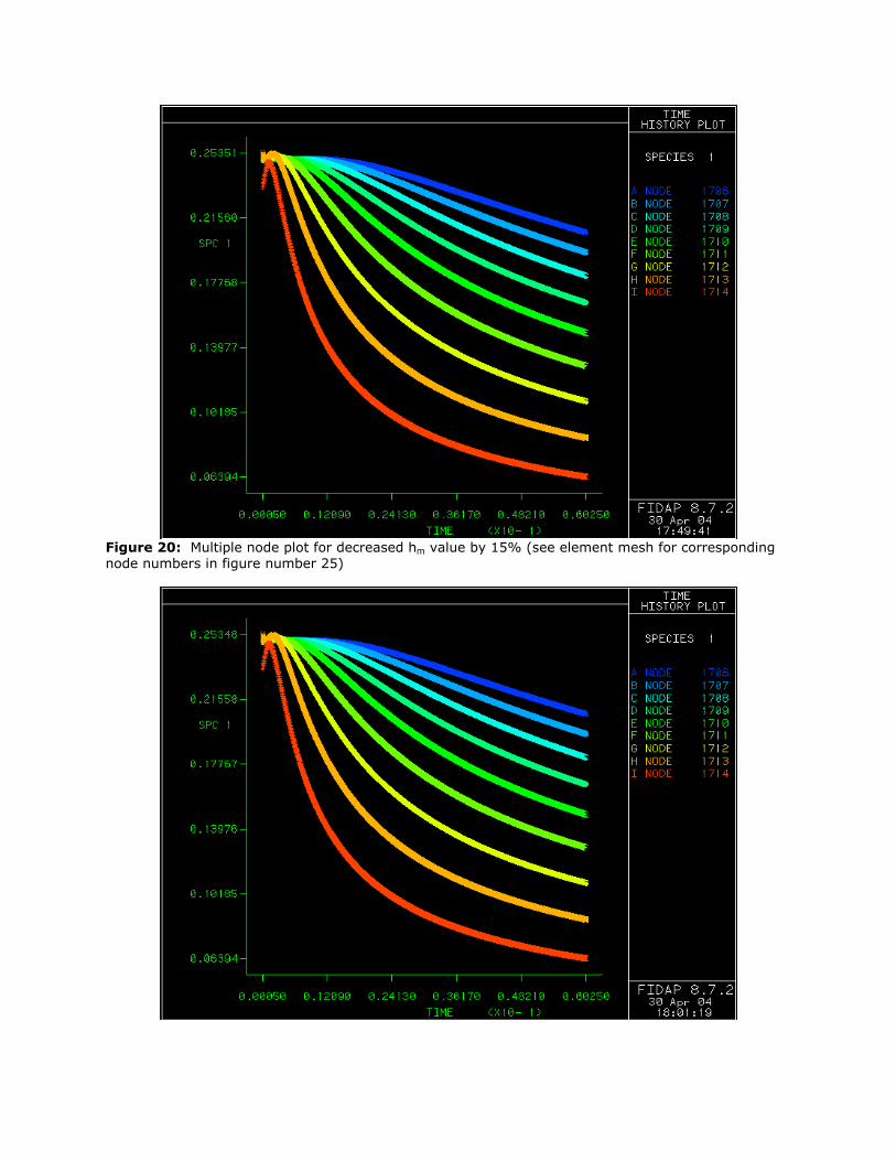
Figure 20: Multiple node plot for decreased hm value by 15% (see element mesh for corresponding node numbers in figure number 25)

Figure 21: Multiple node plot for increased hm value by 15% (see element mesh for corresponding node numbers in figure number 25). This solution is nearly identical to Figure 20, which shows that there is very little dependence on the hm value.
Figure 22: Solution contour for an increase in initial concentration of 15%. The solution looks nearly identical to Figure 16, showing that the solution is not severely dependent on the initial condition.
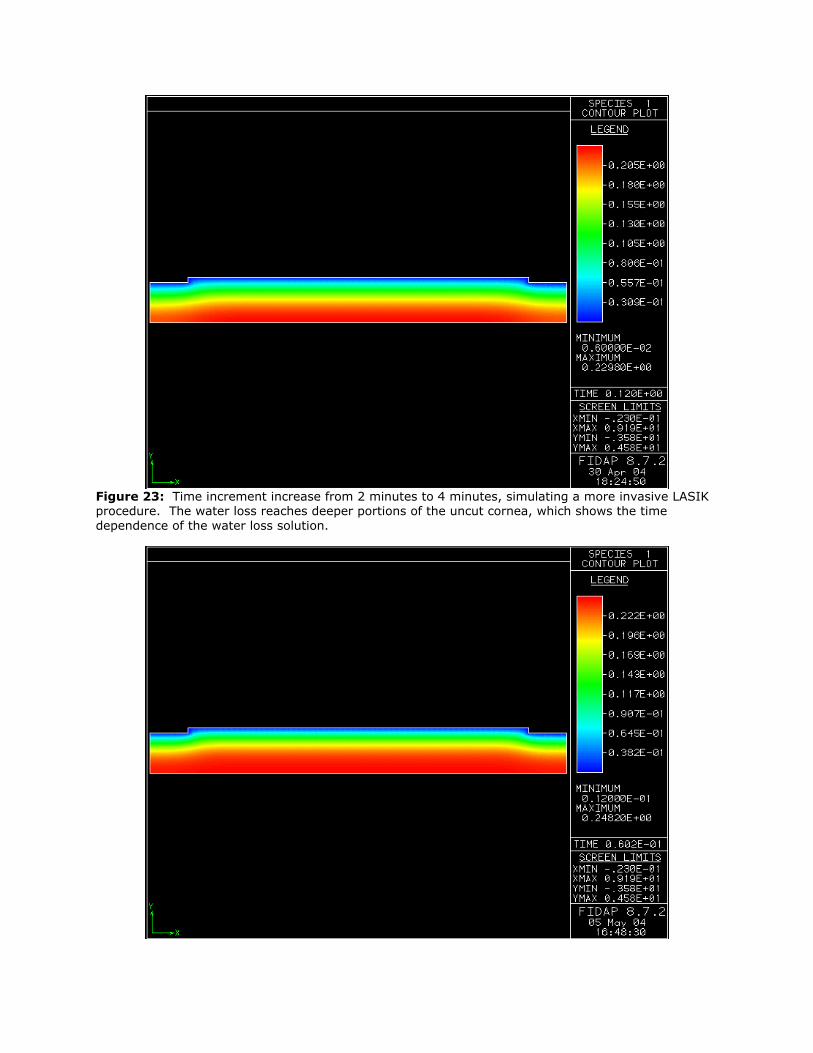
Figure 23: Time increment increase from 2 minutes to 4 minutes, simulating a more invasive LASIK procedure. The water loss reaches deeper portions of the uncut cornea, which shows the time dependence of the water loss solution.

Figure 24: Increase in relative humidity of the operating room to 60% from the original 30%. This changes the initial ambient conditions. There was no significant change due to this variation, and there is little dependence of relative humidity to our solution.
Figure 26: Species solution after a time interval of 1.5 seconds. There is very little water loss after this short time as compared to our final solution seen in figure 16. Appendix D – Works Cited
Ambrosio, Renato. Complications of Laser In Situ Keratomileusis: Etiology,
Prevention, and Treatment. 2001. Journal of Refractive Surgery Volume 17, Pages 350-379.
Geankoplis, C. J. Transport Processes and Unit Operations. 1993. Prentice Hall,
New York, NY. Page 535. Hoch, Gavin. Permeability and Diffusivity for Water Transport Through Hydrogel
Membranes. 2003. Journal of Membrane Science. Volume 214, Pages 199-209.
Lewis, C. “Laser Eye Surgery: Is It Worth Looking Into?” Retrieved May 6, 2004
from <http://www.fda.gov/fdac/features/1998/498_eye.html>. McFadden, M. “The LASIK Procedure – What to Expect.” Retrieved May 6, 2004
from <http://www.lasik1.com/LASIK_exp.htm>.

Mirejovsky, Dorla. Water Properties of Hydrogel Contact Lens Material: A Possible Predictive Model for Cornea Desiccation Staining. 1989. Biomaterials Volume 14 Issue 14, Pages 1080-1088.
National Eye Institute Website. Retrieved May 7, 2004 from
<http://www.nei.nih.gov>.
Redlin, Michael. Managing Hospitality and Engineering Systems. 1987. American Hotel and Lodging Association, Lansing, Michigan.
Vongthongsri, Arun. Laser In Situ Keratomileusis Corneal Flap Creation With the
Nidek MK-200 and the Carriazo Barraquer Microkeratomes. Retrieved May 7, 2004 from <http://jrs.slackinc.com/vol162s/Vong.pdf>.
Young, Donald. A Brief Introduction to Fluid Mechanics, 2nd Edition. 2000. John Wiley
and Sons, New York, NY.