Embed Size (px)
Citation preview

The reservoir development of the Late Maastrichtian–Early Paleocene
Ormen Lange gas field, Møre Basin, Mid-Norwegian Shelf
J. GJELBERG,1 O. J. MARTINSEN,1 M. CHARNOCK,1 N. MØLLER2
and P. ANTONSEN2
1 Norsk Hydro Research Centre, PO Box 7190, N-5020 Bergen, Norway
(e-mail: [email protected])2 Norsk Hydro Exploration & Production Norway, N-0246 Oslo, Norway
Abstract: The giant Ormen Lange Gas Field is situated in the Møre Basin, Norwegian Sea, at water depths
around 1000 m. The reservoir interval consists of a lower heterolithic unit mainly of Maastrichtian age (Jorsalfare
Formation) and an upper sandstone unit of Danian age (Egga Member, Vale Formation), separated by a widely
distributed mudstone unit (‘Vale Tight’), and consists of both high and low density turbidites in association with
fine-grained background sediments. The reservoir interval spans the Cretaceous–Tertiary boundary, without any
major stratigraphic breaks. The main architectural elements of the reservoir are: channel-dominated deposits,
channelized lobe deposits and non-channelized frontal splay or fan fringe deposits. The spatial distribution of
these facies elements indicates a dynamic system with changing sediment supply through time. Core and log
studies from the wells have been integrated with high-resolution biostratigraphy to develop a dynamic
depositional model.
During latest Cretaceous and Paleocene times, a series of subtle sub-basins developed along the southeastern
Møre Basin margin as a result of differential subsidence above Jurassic extensional faults. The sub-basins created
a stepped slope topography that influenced the flow pattern of turbidity currents.
In a landward position, east of the Ormen Lange Field, the Cretaceous–Tertiary boundary is characterized by a
major unconformity, implying erosion and sediment by-pass. In early Danian time, uplift and rotation of the
provenance area to the east (Norwegian mainland) led to extensive erosion and redistribution of sandy sediments
into the Møre Basin and caused deposition of the Egga Member. The turbidites filled the intraslope basins initially
in a basinwards-stepping sense, but later sedimentation switched landward.
Onshore structural, provenance and geomorphological data, combined with offshore structural, seismic and
sedimentological data, yield an integrated interpretation of the deep-water depositional system in the greater
Ormen Lange area. Present fjords at Møre, controlled by the Møre–Trøndelag fault zone, were valley systems
that fed sands to a point source updip of the Ormen Lange area. The point source was located at the
transition/relay zone between a narrow shelf area in the south and a broad shelf area in the north. In addition to
being a key transition zone for both Caledonian and Jurassic structures, this zone area is also the ‘landing’ point of
the major oceanic Jan Mayen Fracture Zone.
Keywords: Ormen Lange Field, Paleocene, Maastrichtian, Møre Basin, basin floor fan, Egga Member, Vale
Formation, K–T boundary
The giant gas field Ormen Lange, in the southeastern Møre Basin
(Fig. 1) was discovered by Norsk Hydro in 1997. The field contains
about 500 £ 109 m3 of gas (GIIP). This paper reviews the
depositional history of the Ormen Lange Field from source area
to deep-water basin sink and revises and extends the work of
Vagnes et al. (1998), Gjelberg et al. (2001), Martinsen & Gjelberg
(2001) and Smith & Møller (2004). The new data include onshore
geomorphological, structural and provenance data with offshore
seismic and new well data. In addition, a new biozonation for all
the wells in the field has been considered in the depositional model.
Attempts to gain information on primary sedimentary deposi-
tional and morphological features from seismic attribute maps
were unsuccessful. Therefore, the stratigraphic and sedimentary
information from the five wells drilled on the Ormen Lange
structure are of essential importance in understanding the
sedimentological development of the Ormen Lange reservoir.
For all wells cores were cut through most of the reservoir, giving
important samples for studies of reservoir parameters, mineralogy,
biostratigraphy, fluid inclusions and palaeomagnetism.
Structural framework
Jurassic structural configuration
The Ormen Lange structure is one of several Cenozoic dome
structures formed in the Norwegian–Greenland Sea (Blystad et al.
1995). The onset of doming and creation of the Ormen Lange
structure closely coincided with the onset of seafloor spreading in
the Norwegian–Greenland Sea (Dore et al. 1997), suggesting a
change in the far-field plate-tectonic stress as a possible causal
mechanism. Significant compression occurred during Oligocene–
Miocene time and appears to have continued up to the present
(Vagnes et al. 1998).
The development of the Ormen Lange structure was strongly
influenced by reactivation of underlying late Jurassic and early
Cretaceous fault blocks, resulting from Jurassic extension on
mainly NE–SW orientated faults south of the Trøndelag Platform
and the Halten Terrace (Blystad et al. 1995; Grunnaleite &
Gabrielsen 1995; Gjelberg et al. 2001). Several N–S-trending faults
also are present in the Klakk fault complex (Blystad et al. 1995)
GJELBERG, J., MARTINSEN, O. J., CHARNOCK, M., MØLLER, N. & ANTONSEN, P. 2005. The Late Maastrichtian–Early Paleocene Ormen Lange gas field.In: DORE, A. G. & VINING, B. A. (eds) Petroleum Geology: North-West Europe and Global Perspectives—Proceedings of the 6th Petroleum GeologyConference, 1165–1184. q Petroleum Geology Conferences Ltd. Published by the Geological Society, London.

and align with the present western margin of the Frøya High. There
is ample seismic evidence that several Jurassic faults were
reactivated during the Cretaceous period (e.g. Brekke 2000). In
addition, because the Cretaceous period was dominated by fine-
grained sedimentation, albeit with high rates of deposition in the
Late Cretaceous, the relief created was sustained for long periods
of time after the Jurassic because of differential subsidence and
compaction. Major structures, such as the Slørebotn Sub-basin, the
Gossa, Vigra, Ona and Frøya highs (Fig. 1) and the Ormen Lange
anticline are, thus, likely to have acted as basinal highs and lows,
trapping or controlling the distribution of latest Cretaceous and
Palaeogene deep-water sediments. The primary distribution ofthick Paleocene sands within the Slørebotn Sub-basin (Fig. 2) isclear evidence of the role of the Jurassic structures in controllingPaleocene deep-water sedimentation with important implicationsfor the distribution of reservoir sandstone within the Ormen Langelicenses.
Cenozoic uplift
Recent work both in the northern North Sea and in the mid-Norway area suggests that several phases of uplift of Fennoscandiatook place through the Cenozoic (Riis & Fjeldskaar 1992;Martinsen et al. 1999; Brekke et al. 2001; Gjelberg et al. 2001).Plio-Pleistocene uplift is best documented, but the presence ofseveral unconformities of regional extent and a significantly tiltedsuccession on seismic lines supports that at least five phases ofuplift may have occurred (Martinsen et al. 1999): LatestMaastrichtian and earliest Paleocene; Early Eocene; EarlyOligocene; Early–mid Miocene; and Plio-Pleistocene.
While the last phase is closely linked to Plio-Pleistoceneglaciations (Riis & Fjeldskaar 1992), the preceding phases areprobably tied to regional tectonics (Martinsen et al. 1999).The latest Maastrichtian–early Paleocene phase is of interestto the Ormen Lange geological story because it may have been theprimary cause for the supply of clastic material from theNorwegian mainland to the deep-water areas in the Møre Basin(Gjelberg et al. 2001). Sands were delivered into a basin, whichthroughout most of the Cretaceous was dominated by deposition offine-grained material (Dalland et al. 1988; Vergara et al. 2001).The mechanism for this uplift phase was probably shoulder upliftof the basin margin, taking place prior to Atlantic break-up.
Shelf and onshore extension of oceanic fracture zones
Several NW–SE oceanic fracture zones occur within the Møre andVøring basins (see Brekke (2000) and references therein). One ofthese zones, the Jan Mayen Lineament, is of importance to theOrmen Lange area (Fig. 1). The postulated onshore extension ofthis lineament coincides with the southern extension of the Klakkfault complex, the southern end of the Frøya High and thenortheastern end of the Gossa and Ona highs. As will be shownbelow, this area coincides with the postulated position of the feedersystem to the greater Ormen Lange deep-water depositionalsystem. Thus, it is assumed that the presence of the Jan MayenLineament had some influence on the delivery of latestMaastrichtian and earliest Paleocene sand to the deeper-waterareas in the Møre Basin prior to Atlantic break-up.
Onshore geomorphology
Present-day fjords onshore mid-Norway show a systematicsemi-rectangular pattern. This pattern corresponds with the long-lived structures of the Møre–Trøndelag fault zone (Fig. 1). TheNE–SW-orientated fjord segments are orientated slightly obli-quely with respect to the present-day coastline and several appearto converge towards the area near the mouth of the Romsdalsfjord.This convergence area is located immediately inboard of thestructural relay zone from which the Ormen Lange deep-waterdepositional system was sourced (see below). It is assumed thatbecause of the long-lived structural context, the fjords occur informer palaeovalleys along which sediments were transportedto the offshore area upslope of the Ormen Lange Field. Theirorientation caused a sediment sink near the mouth of the present-day Romsdalsfjord, from which the sediments were remobilizedand transported onwards to deep-water areas in the Møre Basin.This assumption is supported by the fact that the updip extensionof the mapped sand thickness at Ormen Lange can be traceddirectly into this area and that no other deep-water fan point sourcehas been identified in the area.
Fig. 1. (a) Location of the Ormen Lange structure in relation to the Jan
Mayen Fracture Zone. (b) Jurassic Structural elements at the eastern
margin of the Møre Basin, with the location of the Ormen Lange Field and
the extension of the Jan Mayen Lineament towards the Norwegian
mainland.
J. GJELBERG ET AL.1166

Fig. 2. Correlation of the Cretaceous and Tertiary succession along the eastern margin of the Møre Basin. The Egga Member is located above a major unconformity spanning the K–T boundary. The member consists mainly
of relatively shallow-water, delta front turbidites.
TH
EL
AT
EM
AA
ST
RIC
HT
IAN
–E
AR
LY
PA
LE
OC
EN
EO
RM
EN
LA
NG
EG
AS
FIE
LD
11
67

Basin physiography
Shelf areas
The broad Trøndelag Platform and the Halten Terrace are mainstructural features to the north of the southeastern Møre Basin area.The relative distance to the Cretaceous–Cenozoic deep-waterareas across these structural elements is comparatively muchlarger than from the Norwegian mainland across the SlørebotnSub-basin (sustained by interpretations of sedimentary succes-sions; see Dalland et al. (1988) and several papers in Martinsen &Dreyer (2001)). It is tempting to interpret this difference as areflection of the presence of a wide Cretaceous–Cenozoic shelfalarea in the Trøndelag Platform/Halten Terrace area, while a muchnarrower shelf existed at the eastern margin of the Møre Basin,probably reflecting change in plate polarity (i.e. change from upperto lower plate configuration) across the Jan Mayen Fracture Zone.This had important influence on the effectiveness with which sandswere delivered to the deeper-water areas in the Møre Basin.
Sub-basin areas
Based on the present-day position of main structural features (Fig. 1)and the time isochore distribution of latest Cretaceous and earlyPaleocene sediments (Fig. 3), it is argued that the greater OrmenLange area seafloor topography consisted of a series of struc-turally bounded lows or ‘minibasins’ (Fig. 3). The assumption thatJurassic structures had some influence on the distributionofz sediments also in the latest Cretaceous and early Paleocene
(see above) introduces ideas that several minor sub-basins or
‘minibasins’ could have existed between the Norwegian mainland
and the Møre Basin floor. Within the Cretaceous and early
Paleocene sub-basins at the eastern margin of the Møre Basin, the
sediment influx was probably so high that the rate of sedimentation
most of the time outpaced rates of structural movement, leaving
sub-basinal areas without significant seafloor depressions. How-
ever, in periods with high tectonic activity and relative low
sediment input, shallow seafloor depressions may have developed
above these basins.
There are four smaller basins.
. The Slørebotn Sub-basin (Blystad et al. 1995) is located
between the Gossa High, the transition to the Frøya High (Fig.
3) and the present truncation line underneath the sub-
Pleistocene unconformity. This basin has, by far, the thickest
Paleocene succession (at least 200 ms in places). Gjelberg et al.
(2001) have discussed the Tertiary fill of the sub-basin, where-
as Jongepier et al. (1996) have discussed the Mesozoic fill.
. The ‘Frøya High sub-basin’ (informally named here) is located
along the eastern margin of the mapped area.
. The ‘Gossa sub-basin’ (informally named here) (Fig. 3)
encompasses the eastern part of the Ormen Lange licenses
and is limited to the east by the thickness reduction at
the border to the Slørebotn Sub-basin and to the west by the
constriction in the thickness anomaly at the border to the
Ormen Lange system itself. This basin has a much smaller
Paleocene sediment thickness than the Slørebotn Sub-basin.
Fig. 3. Time isochore map for the Upper Maastrichtian/Lower Paleocene succession at the eastern margin of the Møre Basin with definition of
‘sub-basinal’ areas.
J. GJELBERG ET AL.1168

The structural definition of this proposed sub-basin is poor,particularly at its downdip end at the passage to the OrmenLange area where the thickness seems to be retained but theplan view extent of the Paleocene system is clearly reduced.
. The Ormen Lange ‘sub-basin’ (Fig. 3) (informally namedhere) is defined at its southeastern end by the abrupt eastwardturn of the isochore anomaly from the main N–S trend of theOrmen Lange system and at its eastern end by a suddenthinning, probably caused by reactivation of an underlyingJurassic fault. This sub-basin extended to the north, towardsthe location of the 6305/1-1 well where Paleocene sandstones,albeit with reduced reservoir quality also occur.
Admittedly, the delineation of the four sub-basins is defined bysediment distribution (Fig. 3), but coincidence of basin boundarieswith underlying Jurassic structures is compelling.
The present-day subsurface structural morphology of the greaterOrmen Lange deep-water system area is considered to besignificantly influenced by post-Paleocene movement and uplift/subsidence along major structures of Fennoscandia. The structuralpicture in the area is mainly inherited from the Jurassic (seeabove), but later uplift obviously created structures such as theOrmen Lange Dome (e.g. Brekke (2000) and references therein).These later movements, thus, resulted in the observation thatpreviously deep-water sands, which obviously were originallydeposited in lows, are now on structural highs.
Maastrichtian and Paleocene stratigraphical framework
The reservoir interval of the Ormen Lange Field comprises sandboth of Maastrichtian (Springar/Jorsalfare Formation) and Danianage, informally called the Egga Member (Gjelberg et al. 2001). TheEgga Member comprises the lower part of the Vale Formation(Danian age). In addition to the Vale Formation, the Paleocene ofthe Møre Basin also comprises the Lista Formation (Selandian) andthe Sele Formation of latest Paleocene–earliest Eocene age (Fig. 4).In the Møre Basin it is generally difficult to distinguish between theSele and Lista formations, based on the original definition ofIsaksen & Tonstad (1989). They differentiated between the twoformations on the basis of a slightly higher tuff content in the SeleFormation, compared to the Lista Formation below, and an abruptdecrease of interval transit time downwards across the formationboundary. It is, however, easier to apply the Mid-Norwegian shelfstratigraphy of Dalland et al. (1988) for this area, who defined onlyone formation for the entire Paleocene – the Tang Formation –which consists mainly of dark grey to brown claystone, with minorsandstone and limestone. The main change in the Tertiarystratigraphy between the Northern North Sea area and theTrøndelag Platform area occurs close to the Jan Mayen Lineament(Fig. 1) and it is, therefore, reasonable to use this as the geographicalborder for the application of the two stratigraphical schemes.
The most prominent feature of the Maastrichtian and Paleocenestratigraphy in the Møre Basin is the base Tertiary unconformitythat is well developed and present in all wells along the margin(Figs 2 and 4). Most of the Maastrichtian and the lower Paleocenestratigraphy is absent in these wells. The origin and nature of thisunconformity is not well understood; however, it is tentativelysuggested that it may represent an erosion surface related to asignificant relative sea-level fall during the late Maastrichtian andearly Paleocene, where both the basin margin and platform areasmay have been exposed. This relative sea-level fall was probablyrelated to regional epeirogenic uplift of the mainland (Riis 1996;Gjelberg et al. 2001). In the Møre Basin, on the other hand, there isa continuous stratigraphical development throughout the LateCretaceous–Early Tertiary (Fig. 4).
The Egga Member has been introduced as an informal name forthe sandstones of Paleocene age in the wells in the Slørebotn Sub-basin. Within the same sub-basin there are little or no sandstones
of Maastrichtian age because there is a major stratigraphic breakbetween the Campanian and the Paleocene (Fig. 4). This impliesthat the Maastrichtian sandstones of the Springar (Jorsalfare) Fm.in the Møre Basin are, in principle, unnamed.
In the Ormen Lange licenses, a Northern North Sea stratigra-phical nomenclature has been used (cf. Isaksen & Tonstad 1989).This is formally wrong, but since the nomenclature has been usedin reservoir zonation schemes, the task of changing the scheme iscumbersome. In the present paper, the established North Seastratigraphical nomenclature will be used, but with reference to theMid-Norway stratigraphy (sensu Dalland et al. 1988).
Depositional patterns
The Egga Member at the eastern margin of the Møre Basin
The Egga Member has been known as a prominent sandstoneinterval in the Slørebotn Sub-basin area when it first waspenetrated in well 6205/3-1 (Fig. 2). During 1989–1994 severalwells were drilled along the eastern margin of the Møre Basin,from the Selje High in the south to the Frøya High in the north, andthe Egga Member is present in all these wells. It consists of thick,amalgamated medium- to coarse-grained turbiditic sandstones,with a maximum total thickness close to 150 m (Fig. 2). The baseof the Egga Member in the Slørebotn Sub-basin area and in otherareas close to the eastern margin of the Møre Basin is a significantunconformity with the Danian succession, usually overlying strataof Campanian age. In the Halten Terrace and Trøndelag Platform,the base Tertiary unconformity is also well developed, as an angu-lar unconformity in the more proximal regions to the east. None ofthe wells drilled on the Halten Terrace and Trøndelag Platformareas have proven sand above the unconformity and therefore,differ considerably from the development in the Møre Basin.
The Egga Member in the ‘Ormen Lange sub-basin’
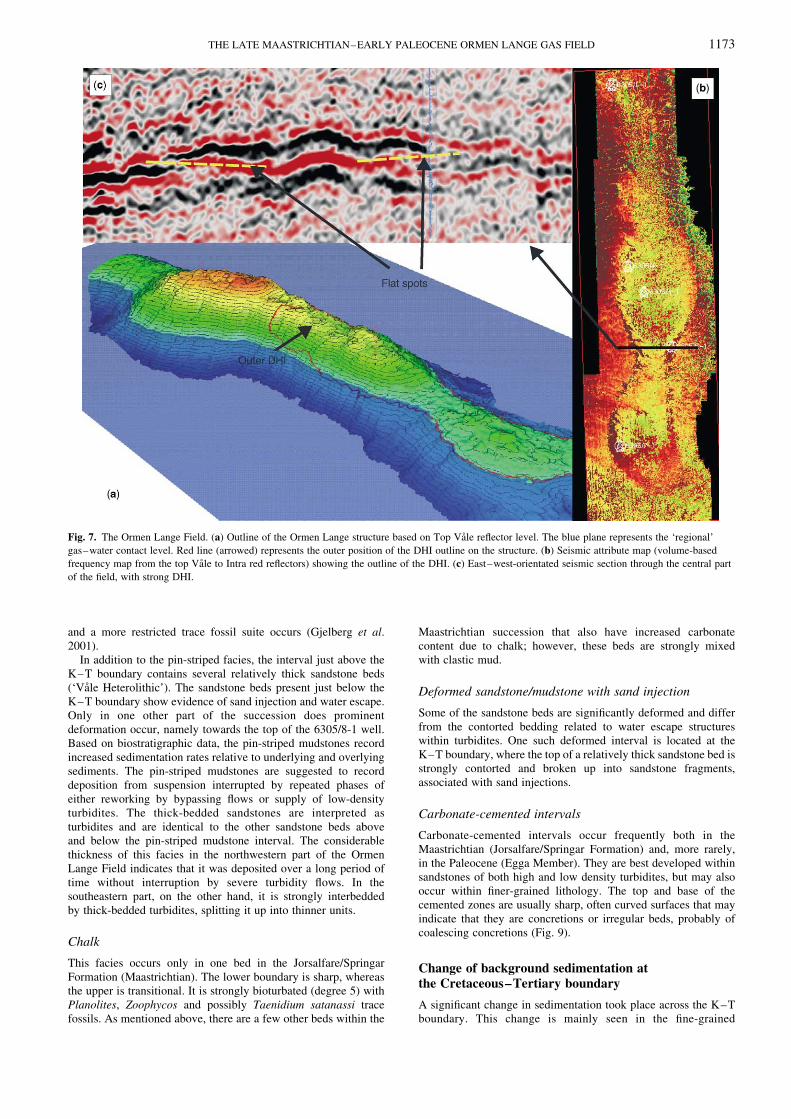
The K–T unconformity was initiated during the Maastrichtian,probably with shelf erosion and sediment bypass. The coarseclastic sediments that bypassed the slope areas were redeposited asturbidites further out in the Møre Basin and represent the reservoirin the Ormen Lange Field, consisting of alternating turbiditicsandstones and mudstones filling in the Paleocene ‘Ormen Langesub-basin’. This development suggests that the generation ofturbidity currents occurred occasionally during long periods ofquiescence, but without significant stratigraphic breaks throughoutthe upper Maastrichtian–lower Paleocene succession. Directhydrocarbon indicators, such as flat spots, amplitude, AVO andfrequency anomalies, are well expressed in the southern andcentral part of the structure (Fig. 5), but become poorly definednorthwards. This poor definition is principally because of poorreservoir quality but also because of poor seismic data caused byseafloor irregularities, shallow gas and a strongly intersectedreservoir related to polygonal faulting (Fig. 6). Seismic attributemaps, on the other hand, suggest that sandy lithologies related tothe Ormen Lange reservoir may be present also in the area justnorth of well 6305/1-1 (Fig. 7). Isochore maps from the EggaMember (based on detailed seismic mapping) suggest that themember is thickest and best developed in the southeastern part ofthe structure, where it shows a radial pattern of thickening andthinning reflecting primary depositional features. It becomesthinner northwards into the saddle area just south of well 6305/8-1,whereas it increases in thickness in the area where well 6305/5-1 islocated (Fig. 7).
The reservoir interval of the Ormen Lange Field comprises theJorsalfare (Springar) sandstones (Maastrichtian) in the lower part,overlain by the Vale Heterolithic and Vale Tight intervals(Danian), accompanied by the Egga Reservoir Unit (Danian),which represents the main reservoir interval. In addition a thinzone called the Egga Tight has been defined in both wells 6305/7-1
THE LATE MAASTRICHTIAN–EARLY PALEOCENE ORMEN LANGE GAS FIELD 1169
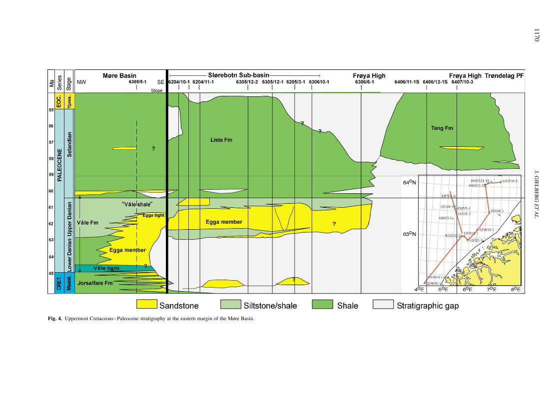
Fig. 4. Uppermost Cretaceous–Paleocene stratigraphy at the eastern margin of the Møre Basin.
J.G
JEL
BE
RG
ET
AL
.1
17
0

and 6305/5-1 on top of the Egga Reservoir Unit. Both theVale Heterolithic/Vale Tight and the Egga Member are parts of theVale Formation (Fig. 8). In addition, a 10–15 m thick shale andsiltstone unit on top of the Egga Member is also included in theVale Formation (Vale shale).
Facies and facies associations of the Ormen Langereservoir unit
Seven process-related facies have been identified within the coredsuccession. Facies identified are based on classical work onturbidite facies (e.g. Bouma 1962; Walker 1967, 1978; Mutti &Ricci Lucchi 1972; Walker & Mutti 1973; Lowe 1979, 1982). Forreservoir modelling purposes only two reservoir facies are applied;these are the ‘C-sand’ (clean sand) and the ‘G-sand’ (low reservoirquality).
High-density turbidity current deposits
This facies consists of massive and vaguely laminated greensandstone (up to 4 m thick), occasionally with abundant greenmudstone clasts (up to 2 cm in diameter). Most of the sands of thisfacies are defined as ‘C-sand’ (Fig. 9). Deformation structurescaused by water escape (e.g. dish structures and contortedbedding) are common in most of the sandstone beds. Normalgrading may occur in the uppermost part of individual beds and
inverse grading is relatively common in the lowermost parts. In
most cases, the grain size distribution is remarkably uniform with
medium, and occasionally medium- to coarse-grained sandstone
dominating. Minor vertical alternations between these grain sizes
are evident within individual beds. Another typical vertical
arrangement of this facies is a massive or graded lower part,
with a non-scoured base, passing upwards into a massive interval
with green mudstone clasts. The mudstones are usually well
rounded, consisting mainly of chlorite and glauconite. Thin
intervals with ripple lamination and convolute lamination may
occur on top of some of these massive sandstone beds. The ripple-
laminated intervals are very thin (few cm) and commonly poorly
developed. Coal fragments are common, especially in the upper
part of the beds. Pyrite aggregates, mica and siderite are common
as additional minerals. Trace fossils include Planolites and
Palaeophycus. Carbonate cements occurs within a few beds of
Facies A and may be restricted to thin intervals, both in the upper
and lower part. The thick beds of this facies may reflect sustained,
near-steady flow conditions with a gradually rising depositional
flow boundary (cf. Kneller & Branney 1995). Beds of this facies
are commonly amalgamated or vertically stacked, with some
thickening–thinning upward trend, probably reflecting lateral
migration of the main feeder system or simply increased/reduced
of energy of the turbidity currents. It is also suggested that the
presence of shallow channels may be responsible for this
arrangement.
Fig. 5. Seismic attribute maps and isochore maps from the Ormen Lange Field: (a) horizon-based seismic amplitude map for the top Vale Formation;
(b) volume-based seismic amplitude map for the top Vale Formation reflector (offset 212 ms, window 24 ms); (c) isochore map for the Lower
Paleocene succession of the ’Ormen Lange sub-basin’.
THE LATE MAASTRICHTIAN–EARLY PALEOCENE ORMEN LANGE GAS FIELD 1171

Low-density turbidity current deposits
Most of the fine- to medium-grained sandstone beds with well-developed normal grading and with a partly developed Boumasequence (e.g. grading from a massive lower part, to parallellamination and occasional ripple lamination at the top) areinterpreted as turbidites of low density currents (Fig. 9). Sandstonein this facies is defined both as ‘C-Sand’ and ‘G-sand’ in themodelling framework. Some sandstone beds with contortedlamination have been assigned to this facies, which is relativelyrare and comprises only a few beds in the cored interval of theOrmen Lange reservoir.
Highly bioturbated greenish sandy mudstone
This facies is common in the upper sand-rich part of the EggaMember, where it separates individual sandy turbidites. In a fewcases sediments of this facies occur isolated within claystoneswithout any association to underlying sand. This is particularly thecase in wells 6305/4-1 and 6305/1-1 T2 where a few such isolatedbeds have been recorded (Fig. 9). Bioturbation mainly comprisesPlanolites, Palaeophycus and occasional Rhizocorallium tracefossils. The depositional processes of the facies are not understoodand it is possible that it may have been deposited as thin sand andsilt turbidites in alternation with hemipelagic shale that later wasmixed by bioturbation. This facies resembles the greenish-greymudstone facies (see below), however, it differs slightly due to itsthinner and sandier development. It represents strongly deformedand bioturbated turbidite tops, often with a gradual upwardstransition to hemipelagic sediments.
Green, greenish-grey and grey mudstones
This facies is very common in the Maastrichtian succession, whereit is present as relatively thick beds (up to 3 m) of alternatinggreen-grey and greenish-grey strongly bioturbated mudstones,with occasional centimetre-thick lenses of glauconite-rich sand.
The mudstones consist mainly of a mixture of calcareous clay and
siltstone, with minor elements of sand. Glauconite grains, pyrite
aggregates and mica occur at most levels. Small shell fragments
are common throughout, but in relatively small amounts. In two
thin intervals there is a significant increase in carbonate, probably
primarily related to increased deposition of chalk. The intensity
and diversity of bioturbation is very high and, in most cases, the
sediments are almost completely homogenized, with no primary
sedimentary structures or lamination preserved. The most common
trace fossils are Zoophycos, Planolites, Palaeophycos and
Helminthopsis horizontalis. These mudstones are interpreted to
be a combination of turbidite mud and hemipelagic and pelagic
mudstones. The greyish and dark green mudstones are probably
hemipelagic in origin, whereas the greener and coarser-grained
mudstones represents mainly turbiditic mud. This interpretation
accords well with the fact that the coarsest mudstones co-occur
with the thickest sandstones, thus these are most likely related
since the most voluminous turbidity currents probably also
transported a considerable mud load. The origin of the green
coloration is from glauconite and chlorite. Since glauconite forms
in marine-shelf environments, incipient glauconite grains may
have been transported via turbidity currents to the deep-water
Ormen Lange system and possibly continued their growth there.
Pin-striped mudstones
This fine-grained lithology characterizes the stratigraphy at and
immediately above the K–T boundary and basically constitutes
the ‘Vale Tight’ unit (Fig. 9). In contrast to other mudstones within
the Ormen Lange area, these mudstones are darker and contain
stripes of siltstone and very fine sandstone which do not exceed
1 cm in thickness (thus, ‘pin-striped mudstones’). The thin
siltstone/sandstone beds show evidence of low-amplitude cross-
lamination. Within the mudstones, the bioturbation intensity
is reduced in relation to the other mudstones in the succession
Fig. 6. Composite seismic line through the wells of the Ormen Lange Field, close to the crest of the structure. The positions of the two important seismic
reflectors, ‘Top Vale’ and ‘Intra Red’ (close to top Jorsalfare Fm.), used in reservoir mapping, are shown. Light blue log curves are gamma logs and dark blue
log curves represent sonic logs.
J. GJELBERG ET AL.1172
and a more restricted trace fossil suite occurs (Gjelberg et al.2001).
In addition to the pin-striped facies, the interval just above theK–T boundary contains several relatively thick sandstone beds(‘Vale Heterolithic’). The sandstone beds present just below theK–T boundary show evidence of sand injection and water escape.Only in one other part of the succession does prominentdeformation occur, namely towards the top of the 6305/8-1 well.Based on biostratigraphic data, the pin-striped mudstones recordincreased sedimentation rates relative to underlying and overlyingsediments. The pin-striped mudstones are suggested to recorddeposition from suspension interrupted by repeated phases ofeither reworking by bypassing flows or supply of low-densityturbidites. The thick-bedded sandstones are interpreted asturbidites and are identical to the other sandstone beds aboveand below the pin-striped mudstone interval. The considerablethickness of this facies in the northwestern part of the OrmenLange Field indicates that it was deposited over a long period oftime without interruption by severe turbidity flows. In thesoutheastern part, on the other hand, it is strongly interbeddedby thick-bedded turbidites, splitting it up into thinner units.
Chalk
This facies occurs only in one bed in the Jorsalfare/SpringarFormation (Maastrichtian). The lower boundary is sharp, whereasthe upper is transitional. It is strongly bioturbated (degree 5) withPlanolites, Zoophycos and possibly Taenidium satanassi tracefossils. As mentioned above, there are a few other beds within the
Maastrichtian succession that also have increased carbonatecontent due to chalk; however, these beds are strongly mixedwith clastic mud.
Deformed sandstone/mudstone with sand injection
Some of the sandstone beds are significantly deformed and differfrom the contorted bedding related to water escape structureswithin turbidites. One such deformed interval is located at theK–T boundary, where the top of a relatively thick sandstone bed isstrongly contorted and broken up into sandstone fragments,associated with sand injections.
Carbonate-cemented intervals
Carbonate-cemented intervals occur frequently both in theMaastrichtian (Jorsalfare/Springar Formation) and, more rarely,in the Paleocene (Egga Member). They are best developed withinsandstones of both high and low density turbidites, but may alsooccur within finer-grained lithology. The top and base of thecemented zones are usually sharp, often curved surfaces that mayindicate that they are concretions or irregular beds, probably ofcoalescing concretions (Fig. 9).
Change of background sedimentation atthe Cretaceous–Tertiary boundary
A significant change in sedimentation took place across the K–Tboundary. This change is mainly seen in the fine-grained
Fig. 7. The Ormen Lange Field. (a) Outline of the Ormen Lange structure based on Top Vale reflector level. The blue plane represents the ‘regional’
gas–water contact level. Red line (arrowed) represents the outer position of the DHI outline on the structure. (b) Seismic attribute map (volume-based
frequency map from the top Vale to Intra red reflectors) showing the outline of the DHI. (c) East–west-orientated seismic section through the central part
of the field, with strong DHI.
THE LATE MAASTRICHTIAN–EARLY PALEOCENE ORMEN LANGE GAS FIELD 1173

Fig. 8. Core–log of the discovery well 6305/5-1, with reservoir units and some palynozone boundaries.
J. GJELBERG ET AL.1174

Fig. 9. Some core examples of the Ormen Lange reservoir in well 6305/5-1. (a) Turbidites and greenish mudstones within the Jorsalfare Fm. The white bed is the only well-developed chalk bed in the succession.
(b) Turbidites and pin-striped facies close to the K–T boundary. (c) Amalgamated turbidites at the middle part of the Egga Member. (d) Turbidites with interbedded mudstones in the upper part of the Egga Member. Core–log to
the left shows the intervals of the core photographs.
TH
EL
AT
EM
AA
ST
RIC
HT
IAN
–E
AR
LY
PA
LE
OC
EN
EO
RM
EN
LA
NG
EG
AS
FIE
LD
11
75
background sedimentation, which changes from greenish-grey,strongly bioturbated claystones and mudstones of Maastrichtian ageinto dark grey, less strongly bioturbated mudstones of early Danianage. The Maastrichtian mudstones exhibit a high diversity of tracefossils mainly of the Zoophycus ichnofacies together withHelminthoida and Anconichnus, whereas the Danian mudstonesimmediately above the boundary show a very low diversityassemblage (isolated Planolites). The sandstones of the EggaMember are all classified as subarkoses according to the classifi-cation scheme of Pettijohn et al. (1972), with close to 10% feldspar.Mineralogical and elemental composition of the fine-grainedbackground sediments in the well indicate that there is a significantchange across the K–T boundary. The concentrations of kaolinite,mica/illite and calcite decrease significantly upwards across theboundary, whereas smectite increases. The greenish shale is rich inchloritic material compared to the black shales, while the clayminerals glauconite and smectite predominate in the black shales.Pyrite is more common in the black shales than in the greenishshales, while rutile predominates in the latter (Gjelberg et al. 2001).
The change in the background sedimentation occurs slightlybelow the boundary, portrayed by a change from greenish,bioturbated mudstones to dark grey mudstones in the Maastrich-tian succession. However, the most significant change, both withrespect to lithology and ichnofabric occurs at the K–T boundaryitself. Gjelberg et al. (2001) tentatively suggested an extraterres-trial cause, such as a bolide impact to explain the observedgeochemical and sedimentological changes at the K–T boundary.Increased instability of slope sediments and giant-scale slumpinghave been inferred by several authors. Interestingly, Norris et al.(2000) documented that large-scale slumping and sliding of theeastern North Atlantic seaboard during the Cretaceous–Palaeo-gene transition took place, more or less simultaneously with theChicxulub impact in the Gulf of Mexico, even though theseregions were many hundreds of kilometres away. The first changesin background sedimentation at the K–T boundary (from greenishto dark grey and grey mud) seem to occur slightly below thesurface itself and it is, therefore, possible that the changes arerelated to other external causes, such as gradual climatic change.Such changes could have caused stress on the environment makingthe fauna and flora more sensitive to other external influences, suchas bolide impacts.
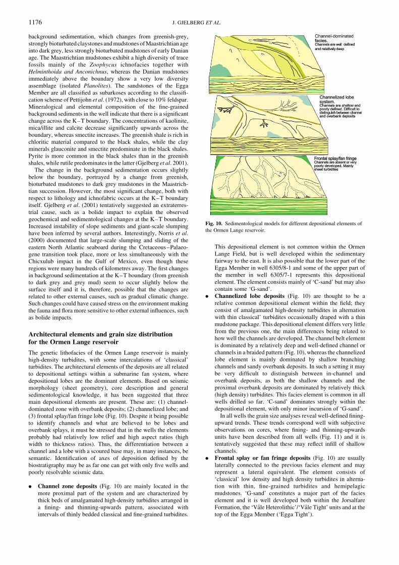
Architectural elements and grain size distributionfor the Ormen Lange reservoir
The genetic lithofacies of the Ormen Lange reservoir is mainlyhigh-density turbidites, with some intercalations of ‘classical’turbidites. The architectural elements of the deposits are all relatedto depositional settings within a submarine fan system, wheredepositional lobes are the dominant elements. Based on seismicmorphology (sheet geometry), core description and generalsedimentological knowledge, it has been suggested that threemain depositional elements are present. These are: (1) channel-dominated zone with overbank deposits; (2) channelized lobe; and(3) frontal splay/fan fringe lobe (Fig. 10). Despite it being possibleto identify channels and what are believed to be lobes andoverbank splays, it must be stressed that in the wells the elementsprobably had relatively low relief and high aspect ratios (highwidth to thickness ratios). Thus, the differentiation between achannel and a lobe with a scoured base may, in many instances, besemantic. Identification of axes of deposition defined by thebiostratigraphy may be as far one can get with only five wells andpoorly resolvable seismic data.
. Channel zone deposits (Fig. 10) are mainly located in themore proximal part of the system and are characterized bythick beds of amalgamated high-density turbidites arranged ina fining- and thinning-upwards pattern, associated withintervals of thinly bedded classical and fine-grained turbidites.
This depositional element is not common within the OrmenLange Field, but is well developed within the sedimentaryfairway to the east. It is also possible that the lower part of theEgga Member in well 6305/8-1 and some of the upper part ofthe member in well 6305/7-1 represents this depositionalelement. The element consists mainly of ‘C-sand’ but may alsocontain some ‘G-sand’.
. Channelized lobe deposits (Fig. 10) are thought to be arelative common depositional element within the field; theyconsist of amalgamated high-density turbidites in alternationwith thin classical’ turbidites occasionally draped with a thinmudstone package. This depositional element differs very littlefrom the previous one, the main differences being related tohow well the channels are developed. The channel belt elementis dominated by a relatively deep and well-defined channel orchannels in a braided pattern (Fig. 10), whereas the channelizedlobe element is mainly dominated by shallow branchingchannels and sandy overbank deposits. In such a setting it maybe very difficult to distinguish between in-channel andoverbank deposits, as both the shallow channels and theproximal overbank deposits are dominated by relatively thick(high density) turbidites. This facies element is common in allwells drilled so far. ‘C-sand’ dominates strongly within thedepositional element, with only minor incursion of ‘G-sand’.
In all wells the grain size analyses reveal well-defined fining-upward trends. These trends correspond well with subjectiveobservations on cores, where fining- and thinning-upwardsunits have been described from all wells (Fig. 11) and it istentatively suggested that these may reflect infill of shallowchannels.
. Frontal splay or fan fringe deposits (Fig. 10) are usuallylaterally connected to the previous facies element and mayrepresent a lateral equivalent. The element consists of‘classical’ low density and high density turbidites in alterna-tion with thin, fine-grained turbidites and hemipelagicmudstones. ‘G-sand’ constitutes a major part of the facieselement and it is well developed both within the JorsalfareFormation, the ‘Vale Heterolithic’/‘Vale Tight’ units and at thetop of the Egga Member (‘Egga Tight’).
Fig. 10. Sedimentological models for different depositional elements of
the Ormen Lange reservoir.
J. GJELBERG ET AL.1176

Fig. 11. Core correlation and general facies distribution between wells in the Ormen Lange Field.
TH
EL
AT
EM
AA
ST
RIC
HT
IAN
–E
AR
LY
PA
LE
OC
EN
EO
RM
EN
LA
NG
EG
AS
FIE
LD
11
77

A general grain size reduction from the channel-dominated
facies to the frontal splay/fan fringe facies is expected. However,
grain size distribution seems to be relatively uniform, as most of
the samples show an average grain size in the fine to medium
range. Grain size analyses (sieve and coulter) suggest that there is a
faint grain size reduction between well 6305/7-1 and 6305/5-1.
This is interpreted as a consequence of proximal to distal
deposition on the submarine fan system, where well 6305/5-1
represents a more distal position compared to the wells 6305/7-1
and 8-1. Within the Egga Member, in well 6305/5-1, the lower part
of the interval (up to 2764 m) tends to have a slightly finer grain
size distribution than the upper part.
Core porosity and permeability data from wells 6305/7-1, 8-1
and 5-1 show a considerable variation both vertically and between
wells. Well 6305/5-1 has porosity values that dominate between
30% and 35% for the Egga Member, but slightly less for the sands
in the Jorsalfare Member. The permeability is more than 1 D
throughout most of the reservoir and up to 2 D within the some
intervals in the upper part. In well 6505/7-1 the porosity is usually
less than 30% in the upper part of the Egga Member and slightly
more than 30% in the lower part, whereas the permeability is less
than 1 D in the upper part and close to 2 D in the lower part. Well
6305/8-1 has porosities between 30% and 35% in the upper part
of the Egga Member, less than 30% in the middle part and more
than 35% for some amalgamated beds at the base. There is a
general trend revealing that the coarser-grained sediments have
both higher porosity and permeability than the finer-grained
turbidites.
Sedimentation in the ‘Ormen Lange sub-basin’
The regional time isochore map of the Paleocene interval within
the greater Ormen Lange area shows an elongate, sinuous
thickness anomaly emanating from the area of the 6306/10 block
running west-northwestwards to the 6305/8 block, then making a
sharp northwards turn and fading out in the 6305/1-1 area (Figs 3
and 7). This isochore anomaly is believed to be a geomorpholo-
gical expression of an extended deep-water turbidite system with
its principal source/feeder area at the intersection between the
northeastern end of the Gossa High, the Jan Mayen Lineament, the
southern end of the Klakk fault complex and the southwestern
margin of the Frøya High (Fig. 1). Therefore, the Ormen Lange
licence area sits within the feeder system to the Ormen Lange
depositional system and is located centrally within the isopach
thickness anomaly.
Detailed seismic morphology of the upper Cretaceous–lower
Paleocene section in the Ormen Lange licence area is difficult to
interpret because of the poor seismic data quality and the strong
overprint of the gas–water contact. Even though thinning and
thickening trends can be seen on isopach maps (Fig. 7), internal
reservoir architecture is not seen either on seismic lines nor on
volume- and surface-based attribute maps (Figs 5 and 7). The
attribute maps tend to highlight the distribution of gas but, in
addition, they may also, to some extent, show the distribution of
sand. These maps suggest that a reservoir with some gas saturation
may be present as far north as well 6305/1-1, but distributed just to
the east of the well.
A series of palaeoenvironmental reconstructions has been drawn
to illustrate the deposition of the latest Maastrichtian and earliest
Paleocene in the ‘Ormen Lange sub-basin’ (Fig. 13). The
reconstructions are based on detailed biostratigraphical analysis
(Figs 8, 11 and 12), combined with regional geological studies and
knowledge. According to the classification system of Reading &
Richards (1994) for turbidite systems in deep-water basin margins
(classified by grain size and feeder systems), the Ormen Lange
reservoir should be regarded as a sand-rich submarine fan system
deposited from a point source.
Early and early late Maastrichtian (Palynozones 31–26)
This period was strongly dominated by greenish mudstonesdeposited as background sediments with interbedded high andlow density turbidites. The turbidites occur sporadically in thevertical section with a tentatively identified thickening-upwardstrend. The thickest sandy development is in the 6305/7-1 well inthe southern region, where more than 20 m of sand-dominatedfacies are recorded. Northwards, the sand intercalations decreaseand, in the 6305/1-1 T2 well, sand is absent even though the totalthickness of the zone increases significantly. Bypass occurred onthe basin margin (evidenced by the biostratigraphy) but it ispossible that some turbidite deposition occurred in the ‘Gossa sub-basin’ at this time. The thickening toward the northwest may beexplained by interfingering of the greater Ormen Lange systemwith other (fine-grained) sedimentary systems (e.g. from the northor west).
Late Maastrichtian (Palynozones 26–18)
This period was dominated by deposition of greenish mudstoneseparated by deposition of thin- to thick-bedded turbiditesandstones, which tend to thicken upwards. This palynozoneinterval shows, in general, little variation between wells 6305/7-1,6305/8-1 and 6305/5-1, both with respect to thickness and faciesdevelopment. However, it is slightly thicker (only a few metres)and sandier in wells 6305/7-1 and 6305/4-1. No turbidites arepresent in well 6305/1-1 T2. The bedding style suggests depositionin a basin plain fed by turbidity currents entering into the basinalong the Ormen Lange fairway to the southeast (Fig. 13).
Latest Maastrichtian–earliest Paleocene(Palynozones 18–16)
This period appears to have been dominated by thicker-beddedturbidite sedimentation than the previous period. Some thick-ness changes occur, where the lowermost Paleocene section inwell 6305/8-1 is a few metres thicker than in well 6305/7-1(Fig. 12), but thicker-bedded turbidite sedimentation seems tohave started earlier in 6305/7-1.
These zones seem to record a progression of sedimentation inthe Ormen Lange fan system, probably related to progradation ofthe system (Fig. 13). The changes in thickness observed may berandom, but emphasis is put on the thick, coarse-grained beds in6305/8-1 well, which can be put into context with later patterns atthis location (see below). Preliminary biozonation suggests thatthere is a considerable thickness increase from well 6305/5-1 to6305/4-1 and that a more than 10 m thick package of amalgamatedturbidites occurs in well 6305/4-1. It is tentatively suggested thatthis thickness increase may be local, related to syn-sedimentaryfaults creating local depressions on the seafloor, or due to anincreased accumulation rate at the western dip-slope margin of the‘Ormen Lange sub-basin’. It has been demonstrated from fieldstudies in Annot (SE France) that turbidites tend to accumulatewith increased thickness along such slopes when the turbiditycurrents hit the slope obliquely (Puigdefabregas et al. 2004).
‘Vale Tight’ reservoir interval: early Paleocene(Palynozone 15)
Palynozone 15 (including the immediately preceding time) isdifferent from any of the other time zones in that the pin-stripedmudstone facies dominates. Palynozone 15 is less than 2 m thick inwell 6305/7-1, but close to 12 m in well 6305/8-1. In 6305/5-1 it isabout 7 m thick and close to 10 m in well 6305/4-1, whereas it isnot identified in well 6305/1-1 T2. The relatively thin developmentof this zone in well 6305/5-1 compared to the 4-1 well may bebecause a small fault crosses the well path in the upper part ofthe zone, implying that several metres have been faulted out.
J. GJELBERG ET AL.1178

Fig. 12. Well correlation on the Ormen Lange Field with gamma-ray logs and biozonation. The zones mentioned in the text are highlighted with thick lines. Cored intervals are indicated with red bars.
TH
EL
AT
EM
AA
ST
RIC
HT
IAN
–E
AR
LY
PA
LE
OC
EN
EO
RM
EN
LA
NG
EG
AS
FIE
LD
11
79

Fig. 13. Palaeoenvironmental setting during deposition of the Ormen Lange reservoir through Late Maastrichtian–Early Paleocene. See Figure 12 for
event zonation.
J. GJELBERG ET AL.1180

The lower part of the palynozone includes turbidites that vary inthickness and facies. The thickest turbidites are located in the 8-1well, where one of the beds is more than 3 m thick and whereturbidites constitute up to 60% of the zone. In well 5-1 twoturbidites are located in the lower part of the zone. Calculations ofdepositional rate of this facies based on the zonation of micro-fossils shows evidence of a much higher sedimentation rate duringdeposition of this mudstone interval than the units below.
The palynozone records a field-wide and sub-basin-widetemporary change of deposition (Gjelberg et al. 2001). The highersedimentation rates and facies change suggest altered sedimentsupply. As alluded to above, this change may be related to slopeinstability during or right after the Chicxulub impact in the Gulf ofMexico. In fact, then, it is the added thickness of mudstone and thepin-stripes that are the anomalous parts of this interval, not theapparent absence of sandstones. The pin-stripes suggest a quasi-continuous supply of fine sand, perhaps as a consequence ofcontinuous release of material on the contemporaneous slope fromsliding and slumping or hyperpycnal flow. Such changes indepositional conditions could also be a consequence of climatic orrelative sea-level changes.
Lower Egga Reservoir Unit, early Paleocene(Palynozones 14–12)
This time period is marked by prominent thickness changes in thewells (Fig. 12). The thickest and coarsest reservoir section occursin well 6305/8-1, where it is approximately 36 m thick, and wherethe bedding pattern of amalgamated high density, relativelycoarse-grained turbidites suggests the presence of channels. The
interval is only 17 m thick in well 6305/7-1 and 23 and 16 m thickin wells 6305/5-1 and 4-1, respectively. The biozones in thelowermost part of this unit (Events 14–13) are very thin in well6305/5-1, where a syn-sedimentary fault is taken as the mainreason for the thinning (see above). It is suggested that thedominant coarse clastic sediment influx during this period was inthe 8–1 area, entering the sub-basin through the well-establishedsediment fairways in the southeast (Figs 13 and 14).
Middle Egga Reservoir Unit (Palynozones 12–8)
Zones 12–8 have a more even thickness across the area, but thecoarsest, thickest and most amalgamated beds occur in well6305/5-1, where the unit is approximately 26 m thick and maycontain channelized lobe/channel mouth facies (Fig. 12). Theinterpreted channels are mainly localized along the eastern marginof the ‘Ormen Lange sub-basin’ (Fig. 13), suggesting control bysubtle differential subsidence along this margin; the underlyingJurassic fault trend was possibly the main reason for this. It isinferred that this reservoir zone extends along the eastern marginfurther north than the 8-1 well.
Upper Egga Reservoir Unit, early Paleocene(Palynozones 8–5b)
These zones record a major shift in sedimentation pattern wherethe thickest and coarsest beds now occur in well 6305/7-1, wherethe unit is close to 40 m thick (Fig. 11). The bedding pattern theretentatively suggests the presence of channels with relative coarse-grained, amalgamated beds. The same interval thins (individual
Fig. 14. Early Paleocene palaeogeographical setting for the eastern margin of the Møre Basin, representing the time interval when the Egga Member
was deposited.
THE LATE MAASTRICHTIAN–EARLY PALEOCENE ORMEN LANGE GAS FIELD 1181

beds also thin and fine) towards the north, where the successions inthe 8-1 and 5-1 wells are less than 20 m thick (Fig. 13).
The thickness and facies changes imply that avulsion took placeupslope of the ‘Ormen Lange sub-basin’ and shifted the axis ofchannels towards the south (Fig. 13). However, this period is alsothe interval in which sedimentation seems to have extendedfurthest to the north, where the succession in the 6305/1-1 T2 wellis about 27 m thick. However, it is possible that part of the fine-grained sediment supply in the north came from different sedimentsources than the reservoir sand facies dominating in the southernregion.
Uppermost Egga Reservoir Unit and Egga Tight(Palynozones 5b–3a)
These zones are present both in the southern and central/northernareas of the Ormen Lange Dome, but missing in the 6305/8-1 well.In well 6305/7-1 the zones consist of turbidites separated by thinmudstone interbeds. In well 6305/5-1 this interval was not coredand the log quality is poor and it is, therefore, difficult to evaluatethe lithology. However, it is suggested that it consists of relativelythin turbidites separated by thin mudstones. The absence of thezone in the 8-1 well is not yet understood, but may represent anarea of non-deposition and/or erosion due to tectonically inducedbasin floor topography at the end of deposition of the EggaMember.
Post Egga Member deposition
Following these phases of sedimentation, the Ormen Lange systembecause abandoned, shown by an overall thinning-upwardcharacter in wells such as 6305/8-1. During deposition of theVale Shale the old coarse clastic systems of the Egga Memberwere terminated and fine-grained sediments were deposited fromsuspension over the whole area.
Attribute maps from the top Vale Formation suggest that twominor sediment fairway systems remained active during depo-sition of the overlying Lista Formation, but now crossing thestructure in a west–northwest transport direction (Fig. 13). Thesesystems may represent shallow channels with possible sedimentbypass in the Ormen Lange area and deposition further west.
Subregional palaeogeography andstratigraphical evolution
The time isochore map for the Paleocene succession in the GreaterOrmen Lange area shows two protrusions that are interpretedto define two palaeosubmarine feeder systems stretching fromthe Slørebotn Sub-basin and from the Frøya High area towards theOrmen Lange area (Fig. 3). They occur in the area of theintersection between the northeastern end of the Gossa High andthe southern end of the Klakk fault complex, approximately at thelandward extension of the Jan Mayen Lineament. It is suggestedthat this was a structural weakness zone, which attracted clasticsupply because of a relatively narrow shelf landward of the area(see above). Furthermore, the transition between the Klakk faultcomplex and the faults controlling the Gossa High can beinterpreted as a palaeo-relay ramp between two major faultsystems. This interpretation is supported by the fact that the GossaHigh disappears in this zone. Relay ramps are prime loci ofsediment transport both in non-marine, shallow-marine and deep-water settings in extensional basins (Leeder & Gawthorpe 1987;Leeder & Jackson 1993).
If the deposition within the four sub-basins is genetically linked,two modes of chronological development are possible: (1) fill, orponding and subsequent bypass to successively more basinwardsub-basins, in essence similar to the minibasins of the Gulf ofMexico (Prather et al. 1998; Badalini et al. 2000); (2) initial bypass
by highly effective turbidity currents which flowed to the ‘OrmenLange sub-basin’, later becoming less effective and depositingtheir loads within progressively more landward subbasins.
Isochore data suggest that the Gossa High may have been abarrier to turbidity current flow. However, at its northeastern end,the thickness data indicate that the turbidity currents could bypassinto the ‘Gossa sub-basin’. Therefore, ponding seems to have beeneffective locally within the Slørebotn Sub-basin, but did not play arole in the development of the thickness in the ‘Gossa sub-basin’,in which fill is considered to be older (Fig. 3).
A complicating relationship is that only the Ormen Lange wellsshow a continuous section from the Maastrichtian through thePaleocene. In the wells in the Slørebotn area and on the FrøyaHigh, most of the Maastrichtian and the lowermost Paleocene aremissing. (Thin units of Maastrichtian age may be preserved locallyat the Møre Basin margin as suggested from seismic data andbiostratigraphy from well 6205/3-1.) This observation suggestsinitial bypass through the feeder system to the ‘Gossa sub-basin’ orerosion of most of the eventual Maastrichtian and lowermostPaleocene sediments prior to the deposition of the Egga Member.However, even though the Slørebotn Sub-basin is considered tohave had negative topographic expression at that time, it is mostlikely that little sediment was deposited. Therefore, a lateral shiftmust have occurred or new feeder systems must have beenactivated to explain the fill of this sub-basin.
If the barriers between the sub-basins were very small, an initialbypass phase to the ‘Ormen Lange sub-basin’ is possible. Later,accumulation could have also been initiated in the ‘Gossa sub-basin’. In this scenario, deposition of a coarse-grained lag shouldbe expected in the ‘Gossa sub-basin’, which records dropping frombypassing turbidity currents. An alternative possibility is that therewas no, or a laterally limited, structural barrier between the‘Ormen Lange and the Gossa sub-basins’. In this hypothesis, onlya ‘normal’ proximal–distal relationship would exist with channelsin the ‘Gossa sub-basin’ and more sheet-like elements in the‘Ormen Lange sub-basin’. An important observation may be thatimmediately west of where the prominent northwards protrusion ofthe isochore anomaly in the ‘Gossa sub-basin’ occurs (Fig. 3),there is marked thinning of the isochore. This thinning couldreflect the presence of a subtle high that prevented turbiditycurrents from flowing directly downslope to the Ormen Langesystem. Thus, where turbidity currents were deflected around thesubtle high, the system narrowed significantly and flows enteredthe Ormen Lange system from the southeast rather than directlyfrom the east.
Unfortunately, the seismic resolution is so poor that stratigra-phical relationships within the different sub-basins (apart from theSlørebotn Sub-basin) are impossible to map. Unlike in the Gulf ofMexico sub-basins where baselap/onlap relationships are crucialfor defining ponded and bypass facies assemblages (Prather et al.1998), the situation in the Ormen Lange area is, perhaps, thatstructural relief was so small that a combination of different casesis most likely. Furthermore, the lateral variability of structuralbarriers and sills is important. The Gulf of Mexico model is,therefore, probably not applicable, as this model requires fullysilled basins, which are filled later and bypassed.
A palaeogeographical map for the late Danian/early Paleocene(Fig. 14) illustrates the sub-regional palaeogeographical situationat the eastern margin of the Møre Basin during deposition of thereservoir units of the Ormen Lange Field.
Conclusions
Seismic data from the Ormen Lange structure are of insufficientresolution to yield information about sedimentary facies, deposi-tional morphology and distribution of reservoir units. Regionalstudies and well data are, therefore, crucial to the interpretation ofthe stratigraphical development and distribution of sedimentary
J. GJELBERG ET AL.1182

facies in the reservoir. Regional studies show that the reservoir islocated at the transition zone between the wide shelf of the Halten
Terrace/Trøndelag Platform area and the narrow shelf of the MøreBasin. This zone is defined by the Jan Mayen Fracture Zone and its
extension towards the Norwegian mainland. The lineament
probably represents a polarity change in the initial asymmetricrift basins between Norway and Greenland, with a change from
upper to lower plate across the lineament. The lineament had a veryimportant influence on sediment distribution in the area. Sand was
probably focused into the area through NE–SW-orientated valley
systems that developed along the important Møre–Trøndelag faultzone.
The reservoir rocks consist entirely of turbidites, but comprisearchitectural elements that range from channel-dominated facies,
channelized lobes to frontal splay/fan fringe facies. The reservoir
is best developed in the southern part of the structure, wherechannel facies are common, but tends to become more fine grained
northwards. The reservoir tends to become thinner and probablyfiner grained to the west and northeast of the structure. However, it
is suggested from examination of attribute maps that a sandy facieswith relatively good reservoir properties is present all the way
north to well 6305/1-1, but is mainly developed just east of this
well. The spatial distribution of these facies elements indicates adynamic system with changing sediment focus through time, with
a compensational infill of seafloor palaeotopography,Polygonal faults intersect the reservoir into compartments,
probably with some reduced flow capacity across some of the
faults. Clay smear of phyllosilicates seems to be responsible for thefault-sealing mechanism (cf Fisher & Knipe 1998). Some of the
faults were active during deposition of the reservoir.
The authors want to thank License Pl209 for permission to publish the
article and colleagues from the various companies in the licence for
discussion. Thanks also to E. Berg, J. Bang, L. Stuevold, R. den Oden,
C. Holter, J. A. Tyssekvam, J. Rykkje, R. E. Midtbø and I. Holmefjord for
interesting discussions and contribution of data. A. Hurst and B. Hakes are
acknowledged for reviewing the manuscript and for their suggestions for
improvements.
References
Badalini, G., Kneller, B. & Winker, C. D. 2000. Architecture and processes
in the Late Pleistocene Brazos-Trinity turbidite system, Gulf of
Mexico continental slope. In: Weimer, P., Slatt, R. M., Coleman, J.,
Rosen, N. C., Nelson, H., Bouma, A. H., Styzen, M. J. & Lawrence,
D. T. (eds) Deep Water Reservoirs of the World, Proceedings of the
20th Annual Research Conference, GCSSEPM Research Foundation,
16–34.
Blystad, P., Brekke, H., Færseth, R. B., Larsen, B. T., Skogseid, J. &
Tørudbakken, B. 1995. Structural elements of the Norwegian
continental shelf, Part 2. The Norwegian Sea Region, Norwegian
Petroleum Directorate Bulletin, 8.
Bouma, A. H. 1962. Sedimentology of some Flysh Deposits. Elsevier,
Amsterdam.
Brekke, H. 2000. The tectonic evolution of the Norwegian Sea Continental
Margin with emphasis on the Vøring and Møre Basins. In: Nøttvedt,
A. (ed.) Dynamics of the Norwegian Margin. Geological Society,
London, Special Publications, 167, 327–378.
Brekke, H., Sjulstad, H. I., Magnus, C. & Williams, R. 2001. Sedimentary
environments offshore Norway – an overview. In: Martinsen, O. J. &
Dreyer, T. (eds) Sedimentary Environments Offshore Norway –
Palaeozoic to Recent. Elsevier, Amsterdam, Norwegian Petroleum
Society, Special Publication, 10, 7–33.
Dalland, A., Worsley, D. & Ofstad, K. 1988. A lithostratigraphic scheme
for the Mesozoic and Cenozoic succession offshore mid- and northern
Norway, Norwegian Petroleum Society Bulletin, 4.
Dore, G., Lundin, E. R., Birkeland, Ø., Eliassen, P. E. & Jensen, L. N. 1997.
The NE Atlantic Margin: implications of late Mesozoic and Cenozoic
events for hydrocarbon prospectivity. Petroleum Geoscience, 3,
117–131.
Fisher, Q. J. & Knipe, R. J. 1998. Fault sealing processes in siliciclastic
sediments. In: Jones, G., Fisher, Q. J. & Knipe, R. J. (eds) Faulting,
Fault Sealing and Fluid Flow in Hydrocarbon Reservoirs. Geological
Society, London, Special Publications, 147, 00–01.
Gjelberg, J., Enoksen, T., Kjærnes, P., Mangerud, G., Martinsen, O. J., Roe,
E. & Vagnes, E. 2001. The Maastrichtian and Danian depositional
setting along the eastern margin of the Møre Basin (Mid Norwegian
shelf): implications for the reservoir development of the Ormen Lange
Field. In: Martinsen, O. J. & Dreyer, T. (eds) Sedimentary Environ-
ments Offshore Norway – Palaeozoic to Recent. Elsevier, Amster-
dam, Norwegian Petroleum Society, Special Publication, 10,
421–440.
Grunnaleite, I. & Gabrielsen, R. H. 1995. Structure of the Møre Basin, mid-
Norway continental margin. Tectonophysics, 252, 221–251.
Isaksen, D. & Tonstad, K. 1989. A revised Cretaceous and Tertiary
lithostratigraphic nomenclature for the Norwegian North Sea,
Norwegian Petroleum Society Bulletin, 5.
Jongepier, K., Rui, J. C. & Grue, K. 1996. Triassic to Early Cretaceous
stratigraphic and structural development of the northeastern Møre
Basin, off mid-Norway. Norsk Geologisk Tidsskrift, 76, 199–214.
Kneller, B. C. & Branney, M. 1995. Sustained high-density turbidity
currents and the development of thick massive sands. Sedimentology,
42, 607–616.
Leeder, M. R., Gawthorpe, R. L. 1987. Sedimentary models for extensional
tilt-block/half-graben basins. In: Coward, M. P., Dewey, J. F. &
Hancock, P. L. (eds) Continental Extensional Tectonics. Geological
Society, London, Special Publications, 28, 139–152.
Leeder, M. R. & Jackson, J. A. 1993. The interaction between normal
faulting and drainage in active extensional basins, with examples from
the western United States and central Greece. Basin Research, 5,
79–102.
Lowe, D. 1979. Sediment gravity flows: their classification and some
problems of application to natural flows and deposits. In: Doyle, L. J.
& Pilkey, O. H. (eds) Geology of Continental Slopes. Society of
Economic Paleontologists and Mineralogists, Special Publication, 27,
75–82.
Lowe, D. 1982. Sediment gravity flows: II Depositional models with
special reference to the deposits of high-density turbidity currents.
Journal of Sedimentary Petrology, 52, 279–297.
Martinsen, O. J. & Dreyer, T. 2001. (eds) Sedimentary Environments
Offshore Norway – Palaeozoic to Recent. Elsevier, Amsterdam,
Norwegian Petroleum Society, Special Publication, 10.
Martinsen, O. J. & Gjelberg, J. 2001. Paleocene deep-water depositional
systems along the eastern margin of the frontier Møre and Vøring
basins, Mid-Norway. AAPG Annual Convention, Denver, Colorado,
Program with Abstracts. A126.
Martinsen, O. J., Bøen, F., Charnock, M., Mangerud, G. & Nøttvedt, A.
1999. Cenozoic development of the Norwegian margin: sequences
and sedimentary response to variable basin physiography and tectonic
setting. In: Fleet, A. J. & Boldy, S. A. R. (eds) Petroleum Geology of
Northwest Europe: Proceedings of the 5th Conference. Geological
Society, London, 293–304.
Mutti, E. & Ricci Lucchi, R. 1972. Le tobiditi delt Apennino settentrionale:
introduzione all’analisi di facies. Memorie Societa Geologica
Italiana, 11, 161–199.
Norris, R. D., Firth, J., Blusztajn, J. S. & Ravizza, G. 2000. Mass failure of
the North Atlantic margin triggered by the Cretaceous–Paleogene
bolide impact. Geology, 28, 1119–1122.
Pettijohn, F. J., Potter, P. E. & Siever, R. 1972. Sand and sandstone.
Springer, Berlin.
Prather, B. E., Booth, J. R., Steffens, G. S. & Craig, P. A. 1998.
Classification, lithologic calibration, and stratigraphic succession of
seismic facies of intraslope basins, deep-water Gulf of Mexico. AAPG
Bulletin, 82, 701–728.
Puigdefabregas, C., Gjelberg, J. & Vaksdal, M. 2004. The Annot Sandstone
in the Annot syncline: basin-margin onlap and associated soft-
sediment deformation. In: Joseph, P. & Lomas, S. A. (eds) Deep-water
Sedimentation in the Alpine Basin of SE France: New Perspectives of
the Gres d’Annot and Related Systems. Geological Society, London,
Special Publications, 221, 367–387.
THE LATE MAASTRICHTIAN–EARLY PALEOCENE ORMEN LANGE GAS FIELD 1183

Reading, H. G. & Richards, M. 1994. Turbidite systems in deep-water
basin margins classified by grain size and feeder systems. AAPG
Bulletin, 78, 792–822.
Riis, F. 1996. Quantification of Cenozoic vertical movements of
Scandinavia by correlation of morphological surfaces with offshore
data. Global and Planetary Changes, 12, 331–357.
Riis, F. & Fjeldskaar, W. 1992. On the magnitude of the late Tertiary and
Quaternary erosion and its significance for the uplift of Scandinavia
and Barents Sea. In: Larsen, R. M., Brekke, H., Larsen, B. T. &
Talleraas, E. (eds) Structural and Tectonic Modelling and its
Application to Petroleum Geology, Norwegian Petroleum Society,
Special Publication, 1, 163–185.
Smith, R. & Møller, N. 2004. Sedimentology and Reservoir Modelling of
the Giant Ormen Lange Field, Mid Norway. European Association of
Geoscientists and Engineers Annual Conference and Technical
Exhibition, Firenze 2002, Abstract volume.
Vergara, L., Wreglesworth, I., Trayfoot, M. & Richardsen, G. 2001.
The distribution of Cretaceous and Paleocene deep-water
reservoirs in the Norwegian Sea basin. Petroleum Geoscience,
7, 395–408.
Vagnes, E., Gabrielsen, R. H. & Haremo, P. 1998. Late Cretaceous–
Cenozoic intraplate contractional deformation at the Norwegian
continental shelf: timing, magnitude and regional implications.
Tectonophysics, 300, 29–46.
Walker, R. G. 1976. Turbidite sedimentary structures and their relationship
to proximal and distal depositional environments. Journal of
Sedimentary Petrology, 37, 25–43.
Walker, R. G. 1978. Deep-water sandstone facies and ancient submarine
fans: models for exploration for stratigraphic trans. AAPG Bulletin,
62, 932–966.
Walker, R. G. & Mutti, E. 1973. Turbidite facie and facies associat-
ions. In: Middleton, G. V. & Bouma, A. H. (eds) Turbidites
and Deep Water Sedimentation, Pacific Section, Society of
Economic Paleontologists and Mineralogists, Short Course
Notes, 119–157.
J. GJELBERG ET AL.1184