Embed Size (px)
Citation preview
2646 IEEE TRANSACTIONS ON MAGNETICS, VOL. 2 5 . NO. 3 . MAY 1989
l o - \
0 9 -
X" 0 8 -
07-
06-
The Reduced Impedance Function for Cup-Core
o t x . X .
o +
%. 0
+ 0
&. +
o o O .\ *. *\ + +
OLI \ \ - . . . . . . . x
Eddy-Current Probes
0 5 -
0 4 -
0 3 -
0 2 -
0 1 -
00
Abstract-Eddy-current nondestructive evaluation makes use of fer- rite-core probes for exciting alternating currents in the test piece. The effectiveness of the probe for detecting flaws in the material through changes in its impedance may he assessed from its interaction with an untlawed conductor. For an important class of eddy-current probes, those with ferrite cup-cores, the measured impedance characteristics are governed by a rule-based behavior found from experiments. These findings are in conflict with the elementary circuit theory model of probe-workpiece interaction but are confirmed by a general field-the- ory probe model.
I 00 002 OW 0 0 6 008 0 1 0 1 2 014 O lh
I. INTRODUCTION N EXTENSIVE program of experimental work on A the eddy-current inspection of graphite-epoxy [ 11 has
led Vernon to formulate some empirical rules governing the impedance characteristics of cup-core probes. Al- though graphite-epoxy was of primary interest in the in- vestigation, the rule-based behavior of cup-core probes is not specific to composite materials and may even be valid for a more general class of ferrite core configurations [ 2 ] . This paper explores the theoretical significance of Ver- non's observations.
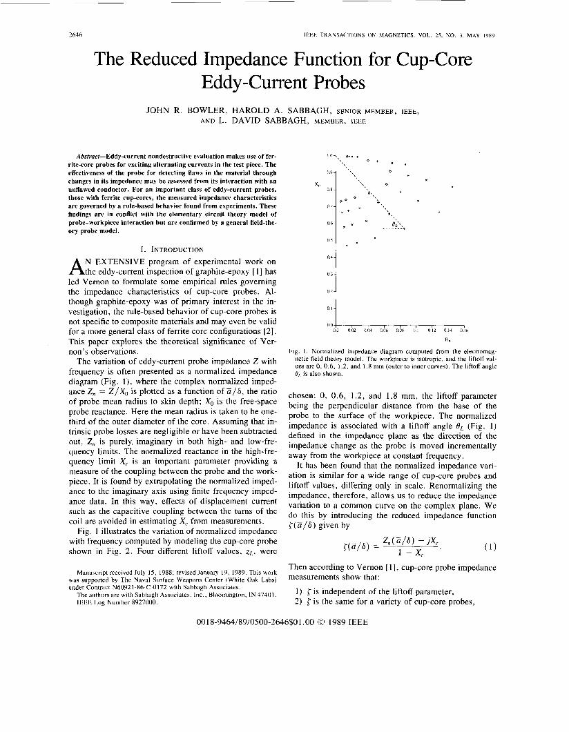
The variation of eddy-current probe impedance 2 with frequency is often presented as a normalized impedance diagram (Fig. l ) , where the complex normalized imped- ance 2, = Z / X o is plotted as a function of Z/6, the ratio of probe mean radius to skin depth; Xo is the free-space probe reactance. Here the mean radius is taken to be one- third of the outer diameter of the core. Assuming that in- trinsic probe losses are negligible or have been subtracted out, 2, is purely. imaginary in both high- and low-fre- quency limits. The normalized reactance in the high-fre- quency limit X, is an important parameter providing a measure of the coupling between the probe and the work- piece. It is found by extrapolating the normalized imped- ance to the imaginary axis using finite frequency imped- ance data. In this way, effects of displacement current such as the capacitive coupling between the turns of the coil are avoided in estimating X, from measurements.
Fig. 1 illustrates the variation of normalized impedance with frequency computed by modeling the cup-core probe shown in Fig. 2. Four different liftoff values, zL , were
Manuscript received July 15, 1988; revised January 19, 1989. This work was supported by The Naval Surface Weapons Center (White Oak Labs) under Contract N60921-8642-0172 with Sabbagh Associates.
The authors are with Sabbagh Associates. Inc., Bloomington, IN 47401. IEEE Log Number 8927000.
Fig. I . Normalized impedance diagram computed from the electromag- netic field theory model. The workpiece is isotropic, and the liftoff val- ues are 0, 0.6, 1.2, and 1.8 mm (outer to inner curves). The liftoff angle Or is also shown.
chosen: 0, 0.6, 1.2, and 1.8 mm, the liftoff parameter being the perpendicular distance from the base of the probe to the surface of the workpiece. The normalized impedance is associated with a liftoff angle OL (Fig. 1) defined in the impedance plane as the direction of the impedance change as the probe is moved incrementally away from the workpiece at constant frequency.
It has been found that the normalized impedance vari- ation is similar for a wide range of cup-core probes and liftoff values, differing only in scale. Renormalizing the impedance, therefore, allows us to reduce the impedance variation to a common curve on the complex plane. We do this by introducing the reduced impedance function { ( a / & ) given by
Then according to Vernon [ 11, cup-core probe impedance measurements show that:
1) { is independent of the liftoff parameter, 2) { is the same for a variety of cup-core probes,
0018-9464/89/0500-2646$01 .OO O 1989 IEEE

2647 BOWLER cl a/ : IMPEDANCE FUNCTION FOR CUP-CORE EDDY-CURRENT PROBES
Fig. 2. Ferrite cup-core eddy-current probe. Dimensions are in millime- ters.
3 ) the liftoff angle is independent of liftoff parameter, 4) tan OL varies linearly with Z/6.
Experimental support for 1 and 3 has been found for zL < 6, Z and results corroborating 4 have been obtained for a range of frequencies such that Z /6 > 1 [l]. Because they are based on a limited set of measurements and sub- ject to experimental errors, it cannot be inferred that the above relationships are valid at all frequencies, or are ex- act. However, they agree with experiment for conditions commonly encountered in nondestructive testing and pro- vide a valuable means of predicting estimates of probe performance. We shall examine the properties of the re- duced impedance function, in relation to a circuit theory model, of probe-workpiece interaction and then compare results computed from our general three-dimensional probe model [ 3 ] with reduced impedance data derived from experimental measurements.
11. EQUIVALENT CIRCUIT ANALYSIS Equivalent circuit analysis is often useful to treat the
system consisting of the probe coil and workpiece as a simple coupled circuit in which the coil plays the role of the primary circuit and the workpiece the secondary, Fig. 3 . We will examine the driving-point impedance of such a circuit, comparing some of the properties of this imped- ance with those produced by the more accurate electro- magnetic model.
Suppose R I is the resistance of the probe and L1 the self- inductance. L2 is the equivalent inductance of the second- ary (the workpiece) and R2 is the equivalent resistance of the workpiece. M is the mutual inductance between the probe and the workpiece. M , L I , and L2 are related by
I
where k is the system coupling coefficient. We define the input impedance 2, as being equal to the total input
Fig. 3 . A coupled-circuit model of the probe-workpiece system. Mesh I models the coil, and mesh 2 the workpiece. M represents the mutual coupling between the two circuits.
impedance less the contribution due to the primary resis- tance R, , and then normalize with respect to the uncou- pled reactance of the probe wL, to give [4]
z , , = j + P - (1 +",x,) ( 3 )
where we have defined a normalized secondary reactance X 2 = w&/R2. The impedance plane diagram is simply a plot of Z, as a function of frequency, for a given value of k and a fixed workpiece. The workpiece manifests itself in the ratio L2/R2 that appears in the definition of X 2 . Clearly, ( 3 ) shows that when w = 0, then Z, = j , and when w = 00, then 2, = j ( 1 - p ) . Thus the intersections of the impedance with the imaginary axis at infinite fre- quency indicate the degree of coupling of the probe to the workpiece.
It is easy to show that the locus of Z,,, as a function of frequency (or X 2 ) , is a semi-circle of radius p / 2 , whose center is a t j ( 1 - p/2). Increasing the liftoff reduces the probe-workpiece coupling and therefore the qualitative ef- fects of liftoff can be observed by varying k; the result is a family of semi-circles whose diameters lie on the imag- inary axis between j and j ( 1 - P ) .
The assertion that the liftoff angle 8, is independent of the coupling (or liftoff) can be easily demonstrated using the coupled circuit model. From (3), the liftoff angle is given by
eL = arg [z, - j ] = -tan-' ( x 2 ) . This is clearly independent of k , but does depend upon the ratio w&/R2,
In order to make further progress in comparing the cou- pled-circuit model with the empirical data, we express the frequency dependence of X2 through the dimensionless ra- tio a/6 . Because X2 is proportional to frequency, the cir- cuit theory model predicts the form X 2 = cy2 ( Z/6)2, where (Y is a dimensionless constant. Hence
(4)
2
taneL = -a'(:)
The coupled-circuit model has the major advantage of simplicity, but it does not accurately describe the correct impedance variation. While it is true that the coupled-cir- cuit model has some correct qualitative features; for ex- ample, in predicting that the impedance plane locus varies in the clockwise sense with increasing frequency; it is not true that the actual locus is a semi-circle. Fig. 4, which is a reduced impedance diagram, shows this very clearly. In this diagram, the effective coupling coefficient is unity.

IEEE TRANSACTIONS ON MAGNETICS. VOL. 25. NO 3. MAY 1989
Reduced resistance
Fig. 4. Reduced impedence diagrams for the coupled-circuit model (dashed semi-circle) and the field theory model (solid line).
Hence the coupled-circuit result is a semi-circle of radius 1 /2, whereas measured reduced impedances have a smaller resistive component over the whole frequency range and have approximately equal real and imaginary parts at high frequencies.
Assuming that liftoff effects are contained in the cou- pling coefficient k , the coupled circuit model agrees with experiment in that the liftoff angle is independent of liftoff parameter. However, the measured frequency depen- dence of the liftoff angle means that tan OL is linear with 3 / 6 , whereas circuit theory predicts the quadratic rela- tionship ( 5 ) .
111. FIELD THEORY MODEL The electromagnetic field excited by a ferrite-core eddy-
current probe is partly due to the coil current and partly generated by the induced magnetization of the core. There are well-known expressions for calculating the field due to a predefined current in a cylindrical coil [5] but the core magnetization is not known a priori and must be com- puted. We have developed a computational model for cal- culating the effects of the core by solving a discrete ap- proximation to a volume integral equation using conjugate gradient methods [3]. This model enables us to calculate the electric field at the coil and from the equation
determine the probe impedance. Here J is the coil current density and the electric field E is computed as a sum of contributions from J and the core magnetization.
The normalized impedances used for Fig. 1 were com- puted in this way, then values of tan OL calculated and plotted against a/6, as shown in Fig. 5 . These results confirm that, to a good approximation, the tangent of the liftoff angle varies linearly with 3 / 6 , although according to the model, data for different liftoff parameters do not lie exactly on the same line. Fig. 6 compares the zero
f
I s 0 x 0.6 mm.
+ 1.2 mm.
s o 0 1.8mrn.
10.0 2n’ni o n 0.0 in o 200 300 40.0 500 U j S 60.0 70 o xn.0
Fig. 5. tan 0, versus the dimensionless parameter i / 6 as computed from the model data of Fig. 1.
a zL material ‘“1 3.75 0 A I
X 3 7 5 1.6 A I
+ 3.75 0 C - c
a16
Fig. 6 . Comparison of the zero liftoff tan Or characteristic for the model data of Fig. 1 (straight line) with experimental results obtained using two different eddy-current probes with an aluminum and a carbon-car- bon composite workpiece. Liftoff parameter zL and mean radius a given in millimeters.
liftoff tan OL characteristic with experimental results ob- tained using two different eddy-current probes with an aluminum and a carbon-carbon composite workpiece. Again good agreement is found between the field theory predictions and experiment.
Using the same model results, the high-frequency re- actance limit X, was estimated for each liftoff value using an extrapolation algorithm. This reactance was then used together with (1) to determine the reduced impedance. Fig. 7 compares the field theory calculation of {with data derived from measurements, showing that the model gives a good fit. However, it is evident that the experimental results have a slightly larger resistive component, possi- bly due to the effects of intrinsic probe losses not ac- counted for in the model.

BOWLER er al.: IMPEDANCE FUNCTION FOR CUP-CORE EDDY-CURRENT PROBES 2649
p’ I I+
a zL material
3.75 0 A I
X 3.75 1.6 A I
+ 1.75 0 c-c 0 4.39 0 c-c
no 0 1 0 2 n 3 0.4 0.5 0 6 0 7 0.x O Y I ( I
Reduced revctnncc
Fig. 7. Comparison of field theory calculation of reduced impedence (solid curve) with experimental data. Liftoff parameter z,, and mean radius a given in millimeters.
IV. CONCLUSION Some empirical rules governing the impedance char-
acteristics of cup-core eddy-current probes have been ex- amined using a general three-dimensional probe model. It has been found that the computed results are in substantial agreement with experiment, thus confirming the rule- based behavior exhibited by measured impedances.
These rules are of interest both from a practical point of view and as a stimulus for further theoretical devel- opments. They provide a compact way of summarizing probe characteristics and a simple means of predicting properties such as the liftoff angle or, knowing the cou- pling coefficient, the normalized impedance at any desired frequency. For the theoretician they provide a new chal- lenge, to determine the functional form of {. The fact that the reduced impedance function is insensitive to liftoff and to details of the core structure suggests that this may be possible using a very simple probe model.
ACKNOWLEDGMENT The authors would like to thank S. Vernon for supply-
ing the experimental data used in this paper.
REFERENCES [I ] S . N. Vernon, “Eddy-current nondestructive inspection of graphite-
epoxy using ferrite core probes,” Naval Surface Weapons Center Rep. NSWC TR 87-148, 1987.
[2] -, Naval Surface Weapons Center, Silver Spring, MD 20903, un- published results.
131
[41
[51
J . R. Bowler, L. D. Sabbagh, and H. A. Sabbagh, “A computational model of eddy-current probes over a stratified composite workpiece,” presented at the 4th Annual Review of Progress in Applied Computa- tional Electromagnetics, in press. H. L. Libby, Introduction to Electromagnetic Nondestructixv Test Methods. C . V. Dodd and W. E. Deeds, “Analytical solutions to eddy-current probe-coil problems,’’ J . Appl . f h y s . , vol. 39, pp. 2829-2838, 1986.
New York, NY: Wiley-Interscience, 1971, p. 157.
John R. Bowler received the B.Sc. degree in physics from Leicester Uni- versity, England, in 1971.
He worked at Berkeley Nuclear Laboratory, Gloucestershire, for the Central Electricity Generating Board, doing research into radiation damage in fast reactor materials. He entered technical education in the UK as a lecturer, and received the M.Sc. degree in science education before return- ing to full-time research. In his doctorial thesis at Surrey University, En- gland, he demonstrated the existence of multi-mode disturbances in gas mixtures, an effect known as double sound. Since 1982 his interests have concentrated in electromagnetic scattering theory and inverse problems, with applications to eddy-current nondestructive evaluation.
Harold A. Sabbagh (S’54-M’58-SM’79) was born on January 9 , 1937, in West Lafayette, IN. He received the B.S.E.E. and M.S.E.E. degrees in 1958, and the Ph.D. degree in electrical engineering in 1964, all from Pur- due University, West Lafayette, IN.
From 1958 to 1961 he was a commissioned officer in the U.S. Navy, and spent the years 1959-1961 teaching electrical science at the U . S . Naval Academy, Annapolis, MD. From 1964 to 1972 he taught at Rose-Hulman Institute of Technology, Terre Haute, IN, achieving the rank of Professor of Electrical Engineering and Physics. He was a research engineer at the Naval Weapons Support Center, Crane, IN, from 1972 to 1980, working in the areas of underwater acoustics, electroacoustics, surface-wave acous- tics, and transient structural dynamics. In 1980 he became President of Sabbagh Associates, Inc., Bloomington, IN. a company that he founded in 1979. The company is dedicated to problem solving and research in the engineering and physical sciences. His principal interests are in computa- tional aspects of electromagnetics, structural dynamics, and quantitative nondestructive evaluation. In the latter area he is concerned with the de- velopment of models, algorithms, and sensors for three-dimensional flaw reconstruction using eddy-currents and electromagnetics.
Dr. Sabbagh is the editor of the IEEE OCEANIC ENGINEERING SOCIETY NEWSLETTER.
L. David Sabbagh (M’83) was born on February 20. 1940, in West La- fayette, IN. He received the B.S. and M.S. degrees in electrical engineer- ing in 1961 and 1962, respectively, the M.S. and Ph.D. degrees in math- ematics in 1964 and 1967, respectively, and the M.S. degree in computer science in 1981, all from Purdue University, West Lafayette. IN.
From 1967 to 1980 he taught at Bowling Green State University (BGSU), Bowling Green, OH, as a member of the Mathematics Department. He returned to BGSU and taught Mathematics and Computer Science, in 1981. In 1982, he taught at Indiana University, Bloomington. He is presently an Adjunct Associate Professor of Computer Science at Indiana University and Vice President of Sabbagh Associates, Inc., Bloomington. His re- search interests include applied numerical analysis, signal and image pro- cessing, and graphics.
Dr. Sabbagh is a member of SIAM, ACM, and Sigma Xi.