Embed Size (px)
Citation preview
CERL Report X-15
THE PLATO IV
STUDENT TERMINAL
JACK STIFLE
November ,1974
Computer- based Education Research Laboratory
University of Illinois Urbana Illinois
This work was supported in part by the Joint Services Electronics Program (U.S. Army, U.S. Navy, and U.S. Air Force) under Contract DAAB 07-67-C-0199; in part by the Advanced Research Projects Agency under grant ONR Nonr 3985(08); in part by Project Grant NPG-188 under the Nurse Training Act of 1964, Division of Nursing, Public Health Service, U.S. Dept. of Health, Education, and Welfare; and in part by the State of Illinois.
Copyright G) November 1974 by Board of Trustees of the University of Illinois
First Printing Revised Revised
March 1970 June 1973 November 1974
Reproduction in whole or in part is permitted for any purpose of the United States Government.
Distribution of the report is unlimited.
THE PLATO IV STUDENT TERMINAL*!
Jack Stifle
Coordinated Science Laboratory
and
Computer-based Education Research Laboratory
University of Illinois, Urbana, Illinois 61801
ABSTRACT
This report describe5 a graphics terminal des igned for use as
a remote computer input-output terminal. The terminal features a
plasma display panel, self-contained character and line generators
and the ability to communicate over voice grade telephone circuits.
* This work was supported in part by the Join t Services Electronics Program (U . S . Army, U. S . Navy , and U.S. Air Force) under Contract DAAB-07- 67-C-0199.
1This report was originally titled, "A Plasr.1a Display Terminal," \..rhen
published in March, 1970 and Mar ch , 1971 .

TABLE OF CONTENTS
CHAPTER 1 - DESCRIPTION Page
1. 0 INTRODUCTION. • • . . • . • . . • • . . • • • • • • • • • • . . • . . . • . . . • . . • . • 1
1.1 TERMINAL DESCRIPTION. • • • • • • • . . • • • • • • • • • • . . • • • • . . • . • • 4
1. 2 AUXILIARY EQUIPHENT .. ....... .. • • • . • • • • • . • • . • . . • . • . • . 6
CHAPTER 2 - OPERATING HODES
2. 0 HORD FORMAT. . • • • • . • • • . • . . . . • • . • • • • • • • • • • • • • • • • • . • . • . 8
2. 1 CONTROL \vORD. • . • • . • • • • • • • • • • • • • . . • • • . • • • • • • • • • • • • . . • 8
2 . 2 MODE HORD. • . • • • • • . • • • • • • • • • • • • • • • • • • • • • . • • . • • • • • • • • • 12
2.3 HODE 00 ••••••••• • ••• •. • • •.•• ••• ••• .•• • ••• ..•.•..••• . 13
2.4 !'10DE 01 •.••.•••• • .•• •.••• .•.•••.• .• ••••• •••• •••.••.• 13
2 . 5 MODE 10 •..•••••• •. •••••.•••• •. •.•••.•..•.•. • ••••.•.• 13
2 . 6 MODE 11 •..•.•••.• . • • •••••. ••.• ••••• • ••••••....•..•.. 15
2 . 7 CONTROL CHARACTERS .. • • • • • • • • • • . . • • • • . • . • • • . • • • . • . . • . 16
2. 8 ERROR CONTROL. • . . • • • . • . • . • • • . • • • • • . . • • • • • • • • • . . • • • • • 21
CHAPTER 3 - TERMINAL GENERATED DATA
3 . 0 DATA SOURCES. • • • • • • • • • • • • . • . • • • • • • • • • . • • • . • . • . • . . • . • 22
3 . 1 OUTPUT HORD FORMAT . . • . • . . • • . . • • • • • • • • • • • • • • . . . . • . • • • 22

A PLATO IV Student Te rminal
CHAPTER 1 - DESCRIPTI ON
1. 0 I nt roduction
Thi s r e port descr ibes t he student t e r minal ( r emote comp uter
t ermi na l) , desi gne d for use in the PLATO IV compu ter- aided- i nstr uc tion (CAT)
sys tem. Al though the t e rmi na l is intended f or 11se i n teach in~ aopl i ca t i.ons ,
it has manv fea tures 1vhich make it useful i n ma ny other computer terminal
aopl i cat i ons . These features include :
1.
3 . ·
4 .
5 .
6 .
7 .
An R 1/2- inch square plasma displav nanel that i s readnhle in a br ight ly light ed room wi t hou t evestrai n .
Pe rma nent s t or age of i nforma t ion on the clisolav sc r een lvithout f li cker. Absolute l y no r ef r eshing of t he disnlay oanel by the computer i s r equi r ed .
Se l f - cont a ined character and l i ne generator s .
A character writ ing sneed of 180 characte r s per second a ncl t he caoability of displa'!ing 11 0 to 204R characters on t he scr een .
A line dra1ving speed of 60 l ines per sec.ond .
A character re~ertoire of 256 charac t ers , 128 of which a r e alter able via the comou ter nr ogram .
The ability to transmit ~nd receive data on voice grade teleohone circuits .
8 . A ranclom- acccss s l ide projec t or for rear nrojec t ion of static informa t ion on t he disolav sc r een.
9 . Addi t iona l inpu t ~ ou tput channels f or th e con t r ol o f a ux i liar v equ i omen t .
10 . An optiona l random-access audio resoonse unit .
There are th r ee ~eneral requirements which mav he used to char ac t e r ize
a CAl computer ten8i nal .
First , the terMinal must be caoable of servi ng t he needs of a br oad

2
class of relatively unsophisticated users, most of ~Jhom \Jill he encountering
computer ter~inals for the first time. Users might include, for example,
grade school students studying arithmetic or geo~raphy, high school students
studying French or Spanish, and college students studying biolo~y or chemistry.
The terminal must present information to each of these users in a form that
he can readilv understand.
Second, the terminal must be capable of re~ote operation via low grade
telephone lines. This requirement is essential to permit the locating of
terminals in widely separate schools without the need for expensive communi-
cation links.
Third, the terminal should cost less than $5000 to be competitive with
1 the present costs of education.
To meet the first requirement mentioned above, the terminal must have
graphical capability. It must be able to present pictoral information such
as maps, ~raphs, circuit diagrams, anatomical drawings, etc. Some type of
line ~enerator which can be used to generate such objects is thus required.
A very versatile character generator is also required. The terminal
must be capable of displaying not only upper and lower case English alpha-
numeric characters, hut also foreign language characters and any special
symbols which may be unique to a particular suhject under study. Such a
need implies a character generator whose repertoire can be dynamically
altered by the computer.
The need for ~oeration over low grade telephone lines implies a limited
1n. Alpert and D. Bitzer, "Advances in Computer-based Education," Science, Harch 20, 1970, Volume 167, pp. 1582-1590.

3
availab le bandwidth of appr ox i ma t e l y 1200 b i t s / s econd . Such low bandwidth
neces si t ates local s t orage of infor mation with i n the termi nal .
Depending upon the data format used , anywhere from 75K to 250K bi t s of
memo r y may be r equi red to sto r e immages for pres entat i on on a cathode-ray
tube (CRT) with 500 line resolution. A relatively high b andwidth , typically
4.5 ~lliz , i s required between this memory and t he CRT to pr event flicker of
the image . Fas t digital to analog (DA) converters may be requi r ed t o inter-
face the terminal process i ng unit t o the CRT .
ilirect viewing storage t ubes may be used t o over come the flicke r prob l em
but these devices suffer f r om l ow b rightness and t he i n ab i lity to perfor m
selective erase operations on the displayed data.
2 The use of a plasma panel , on the other h and , with i t s inherent
memory , eliminates the refres h memo r y while pr es erving the select i ve e r ase
function . Because each point is stored on the panel as it is displayed ,
the terminal electronics need operate only fast enough t o stay ahead of the
incoming da ta. A panel writing r ate of 30 KHz is adequate fo r this applicat i on .
The digital nature of the plasma panel a lso el i minates the need f o r any DA
converters .
The t hin transparent st r ucture of the pl asma panel permi t s the panel
to be used as a sc reen for the viewing of information in the form o f slides
or microfiche which can be projected on the rear of the panel . Such info rma-
2R . L . Johnson , D. L . Bitzer , and H. G. Slo ttow , ''The Device Characteristics of the Plasma Display Elemen t, " IEEE Tr nnsac t ions on El ectron Devices , Vol. ED- 18 , No . 9 , September 1971, pp. 642- 649.

4
tion can be stored in the terminal and projected on the panel, under computer
control, thus providin~ a presentation of dvnamic computer generated data
superimposed on static (slide) data. This local storage of static informa
tion reduces the memory required in the central computer and at the same time
results in more efficient use of the communication link.
1.1 Terminal Description
A blocl: diagram of the prototype terminal is sh01vn in Figure 1.0. The
seria l i nput port is designed to accept data arriving at a rate of 1200
bits./second in the fo rm of a freq uency-modulated (fm) signal, which permits
the terminal t o operate on voice grade telephone circuits . The terminal
\vord size is 20 bits and therefore the terminal word rate is 60 \vords per
second. The terminal word format is discussed i n Chapter 2.
The demodulator recovers the data from the fm signal and shifts the
data into the serial input register (SIR). After a full word has been
assembled in the SIR it is transfe rred t o t he Data (D) Register.
The 20-bit D register is the distri~ution center of t he terminal .
From this r egister data may be transferred to a ll i nternal sections of
the terminal as well as any external equioment connected to the t erminal.
The 5 bit mode register 01) is analogous to the instruction reRister
in a digital computer . This register directs the Terminal Control section
in the processinp, of incoming data. Terminal Control provides the timing
and control signals for cont r olling the flow of data \.Jithin the termi nal.
Four modes of operation are ava ilable and are discussed in Chapter 2.
The data is displayed on a Digivue* Plasma Display Panel . This panel
*Trademar~ of Owens- Illinois, Inc.

Voice Grade ------1~ Line .....__---J
(Serial In put)
Voice Grode Line
Character Genera tor
Terminal Control
(Seria l Output)
Figure 1. Terminal Block Diagram
Line Genera tor
Externa l Input
Channe l
Externa I Output
Channel (15 bits)
Slide Proj
DS-1539
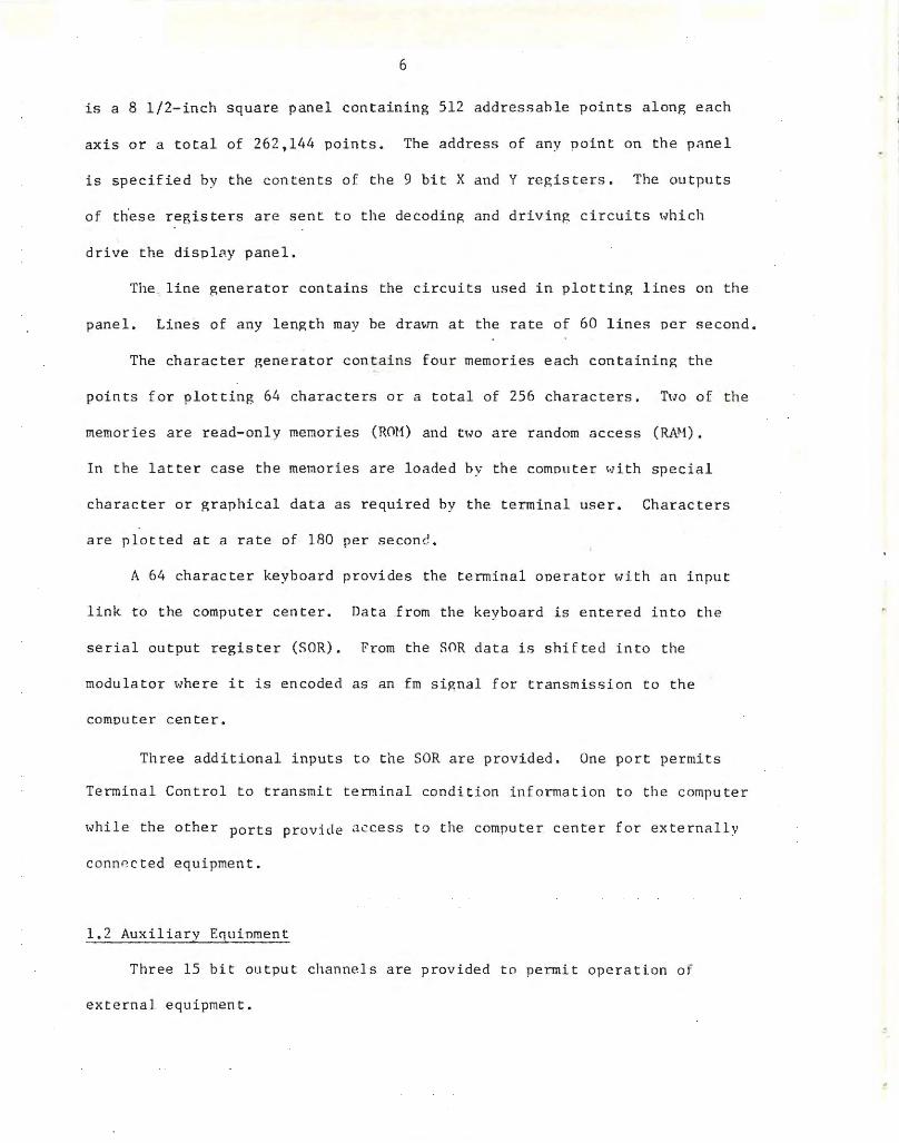
6
is a 8 1/2- inch square panel containing 512 addressable points along each
axis or a total of 262 ,144 points. The address of any poin t on the panel
is specified by the contents of the 9 bit X and Y registers. The ou tputs
of these registe rs are sent to the decoding and driving circuits which
drive the displRy panel .
The line generator contains the circuits used in plotting lines on t he
panel . Li nes of any length may be drat.m at the rate of 60 lines per second .
The character generator contains four memories each containing the
points for plotting 64 characters or a total of 256 charac ters. Two of the
memories are read- only memories (ROM) and t\-10 are random access (RN1) .
In the latter case the memories are loaded hy the computer t.Jith special
charac ter or graphical data as required by the terminal user . Characters
are plotted at a rate of 180 per second .
A 64 character keyboard provides the terminal operator with an input
link to t he computer cent er. Data from the keyboard is entered into th e
serial output register (SOR) . From the SOR data is shifted into the
modulator where it is encoded as an fm signal for transmission t o the
compute r center .
Three additional inputs to the SOR are provided . One port permits
Terminal Control to transmit terminal condition information t o the computer
while the other ports provide access to the computer center for externally
conn~cted equipment.
l. 2 Auxiliary EC1 uinmen t
Three 15 bit output channels are provided to permit operation of
exte rnal equipment .
i •
7
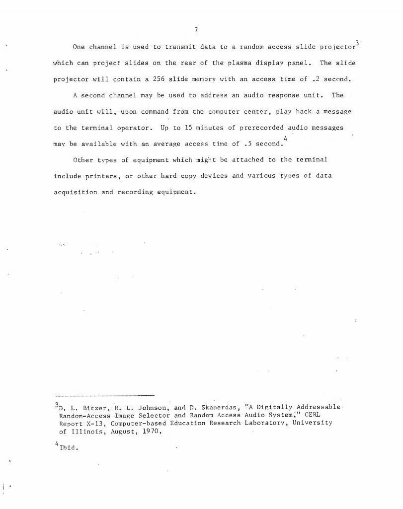
One channel is used to transmit data t o a random access slide projector3
\vhich can project slides on the rear of the plasma display panel . The slide
projector will contain a 256 slide memory with an access time of . 2 second .
A second ch;mnel may be used to address an audio response unit. The
audio unit \vill , upon command from the computer center, play hack a messa~e
to the terminal operator . Up to 15 minutes of prerecorded audio messages
4 may be available with an average access time of .5 second.
Other t ypes of equipment which might be at t ached t o the terminal
include printers, or othe r hard copy devices and various t ypes of data
acquisition and recording equipment.
':1 -'D . L. Bitzer, R. L . Johnson, anti D. Skane rdas , "A Digitally Addres sab le
Random- Access ·I mage Selector and Random Access Audio Sys tern," r.ERL Repor t X-13 , Computer- based Education Research Laboratorv, University of Illinois, August , 1970 .
4Ibid .

8
CHAPTER 2 - O?ERATINr. MODES
2 . 0 Hard Format
The data to be processed by the terminal consists of ~0 hit words
with the format shown in Figure 2.0.
19 18 01 no
DATA
Figure 2 .0 Terminal hlord Format
Bit 00
Bits 01 - 18
Bit 19
Paritv hit - even parity
Data
Control bit 0 - 1
control word data ~vord
Terminal ,.,o rds may be of t~.Jo types ; control words and/or data words. Da ta
v.rords (c 1) contain t he data to be processed hv the terminal ~.Jhile con trol
words (c 0) a re instructions used to establish cer tain conditions ~vithin
the t ermina l.
2 . 1 Contro l Word
The control ~wrd format is shown in Figure 2 .1.
19 18 17 16 15
Bits 01 - 15
Bits 16 - 18
01 00
DATA
Figure 2 . 1 Control \.Jord Forma t
Data
Destination of data within the terminal

9
D 000 (NOP)
19 18 17 16 15 01 00
I o I o o o I 0-----·--- --- - ----- - -------- --------------0 I o I This word is a NOP (no- ope r at i on) instruction . The word is input by
the t ermina l but the te rminal condition is not altered in any way .
D 001 (LDM) Load Mode
19 18 1 7 16 15 14 13 07 06 05 01 00
I 0 I 0 0 l I I I ~ I HORD COUNT TI1is instruction loads the Mode r egister (M) with b its 01- 0 5 . In
addition, if bit 14 (WC) is a "1" the i.Jo r d Count r egister will be l oaded
with bits 07- 1 3. The mode is described in Section 2.2 and t he Wo rd
Count in Sec tion 2 . 8 . Re ce ipt of an LD M i nstruction whi le the terminal is in
t he ABORT mode will l oad t he l.Jord Count r egis ter but \vil l not alter t he Hode
r egister. Bit 15 is used t o actuate or inhib it external devi ces at tached t o
the terminal . Receipt of an LDM instruction with bit 15 = 1 will inhibit all
inputs f r om external devi ces . These Devices wi l l remain inhibited until r eceipt
o f an LDH instru ction with b it 15 = 0.
D 010 (LDC) Load Co-ordinat e
19 18 17 16 15 11 1'1 09 01 00
This inst ru c tion loads the X register (bi t 10 = 0) or the Y r egister
(b i t 10 = 1) with bits 01- 09. Bi ts 11- 15 are unused .
u = 011 ( LDE ) Load Ech o
19 18 17 16 15 08 07 01 00
ECHO
10
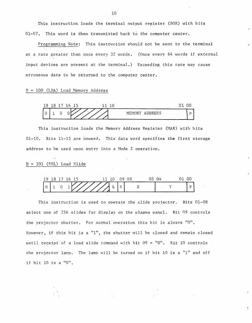
This ins truc t ion l oads the terminal output reRister (SOR) with bits
01-07 . This word is then transmitted back to the computer center.
Programming Note : This instruction should not be sent to the terminal
at a rate greater than once every 32 words . (Once everv 64 words if external
input devices are present at the terminal . ) Exceeding this rate may cause
erroneous data t o be returned to the compute r center.
D 100 (LDA) Load Nemory Address
19 18 17 16 15 11 10 01 00
or00j MEt·IORY ADDRESS
This instruction loads the Memory Address Register (MAR) with hi t s
01-10. Bits 11- 15 are unused. This data word specifies the first storage
address to be used upon entry in t o a Mode 2 operation .
D = 101 (SSL) Load Sli de
19 18 17 16 15 11 10 09 08 05 04 01 00
X y
This instruction is used to operate the slide projector. Bits 01-08
select one of 256 slides for disp lay on the pl asma panel . Bit 09 cont r ols
the projec t or s hut ter . For normal onerati on this bit is al\vavs " 0".
However, if this hit is a "1" , the shutter 1vil l he closed and remain c l osed
unt i l re7eipt of a load slide command with bit 09 = "0". Bit 10 controls
the projector lanp. The lamp ~.Ji ll be turned on if bit 10 is a "1" and off
if bit 10 is a "0".

11
D = 110 (AUD) Load Audio
19 18 17 16 15 01 00
Ia j1 1 AUDIO DATA
This instruc t ion is used to control the audio response unit. The
audio response uni t requires tHo of these ins truc tions pe r audio operation.
The formats of each of these instructions i s described beloH.
15 14 13 12
TRACK
Bits 01 - 12
Bits l3 - 14
Bit 1,5
15 14 08
I I O------ - ------------O I Bits 01 - 07
Bi t s 08 - 14
Bit 1 5
06 OS 01
~- SECTOR
07
Fi rst audio instruction
Specify the message starting address ; bi t s 01 - 05 soecify one of 32 sectors and bits 06 - 12 one of 128 tracks .
Snecify playback or erase as fo l1o•vs :
00 - do no t hing 01 play message 10 - do nothing 11 - record message
A1•Jays " 1". Identi fies fi rst of two audio i ns tructi ons .
HESSAI.E LENGTH IN SECTORS
01 Second audio i nstruction
Snecifv le ng t h of message in terms of sec t ors . One sector equals ~ 1/3 seconds .
Unused
Ah1avs "O" - identifies second audio instrucLion .
12
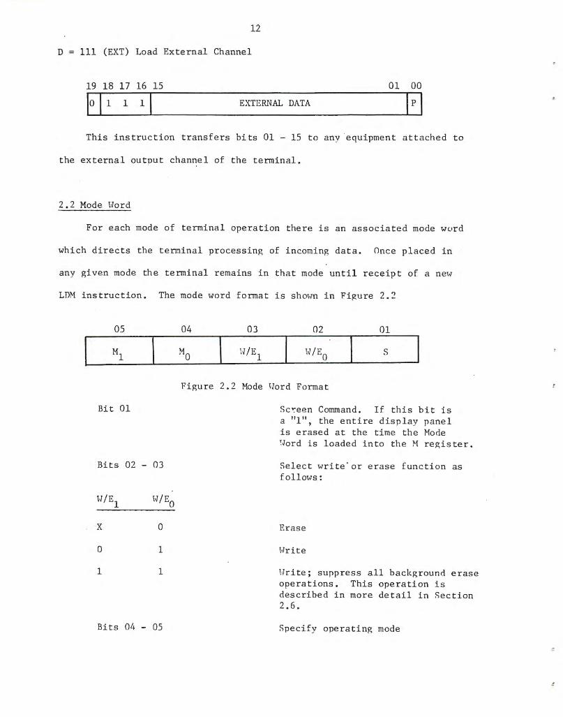
D 111 (EXT) Load External Channel
19 18 17 16 15 01 00
EXTERNAL DATA
This instruction transfe r s bits 01 - 15 t o a ny equipment a ttached to
the external output channel of the terminal.
2 . 2 Mode Hord
For each mode of terminal operation there i s an associa t ed mode \v<-'rd
which directs the terminal processing of incomin~ data. Once placed in
any given mode the terminal r emains i n tha t mode until r eceip t of a ne\v
LDi instruc tion. The mode word forma t is sh mo~n in Fi~ure 2. 2
05
Bit 01
Bits 02 - OJ
W/E 1
X
0
1
0
1
1
Bits 04 - 05
04 OJ 02 01
s
Figure 2 . 2 Mode 11orrl Format
Sc~een Command . If this bi t is a "1", t he entire display panel is erased a t the time the Mode !Jord is loaded into the t regis ter .
Selec t write'o r erase f unction as follmvs :
Erase
I.Jrite
Write; s uppress all background erase ope r a t ions . This operation is described in more detail i n Sec tion 2 . 6 .
Specify ope r a ting mode

13
2 . 3 Mode 00
Mode 0 is a ooint plotting mode. Each mode 0 data \vord (Figure 2.3)
specifies the address of a point on the panel to he written or er~sed . The
H/E0 bit in the mode word detennines \vhich operation i.s perf ormed.
19 18 10 09 01 00
X y
Figure 2 .3 t-bde 0 Data \vord
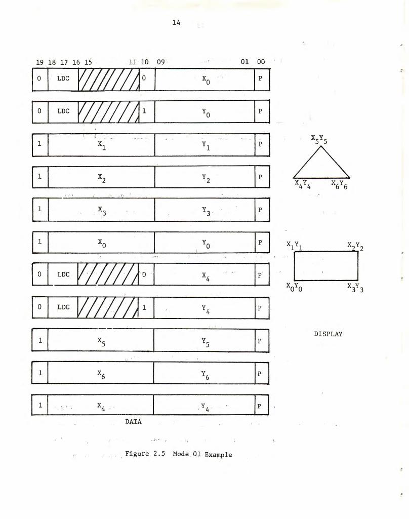
·2 .4 Mode 01
Mode 1 i s a line drawing mode. Each data word, Figure 2.4, specifies
the terminal coordinate s of a line , the origin of which is ccntained in the
X and Y registers.
19 18
X. 1
lQ 09
figure 2 . 4 Mod e 1 Data format
Y. 1
01 00
The terminal point of a Riven line is also interpre t e d as the ori?.in
of the next line . Line origins may be reloca t ed, however, hv the use of
the LDC command 1vi thou 1.: exiting from Node 01.
An example of a node 01 operation is s hmvn in Fi.p,ure 2 . 5.
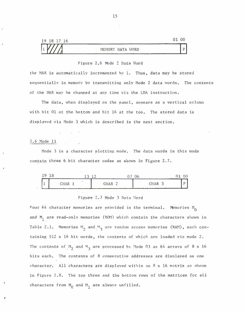
2.5 "1ode 10
Mode 2 is a load tenninal memory mode . Each mode 2 data \vord (Figure
2 . 6) contains a 16 bit word to be stored in the memory location specified
by the presen t contents of the memory address register (MAR) . Up to 1024
16 hit 1vords may be s tored in the terminal. After the da ta has been stored
14
19 18 17 16 15 11 10 09 01 00
f•
DISPLAY
DATA
. Figure 2 . 5 Mode 01 Example
15
19 18 17 16 01 00
HEt10RY DATA ~lORD
Fi gure 2 . 6 t-bde 2 Da t a {Jord
the MAR is au t omatically i nc r emented hy l. Thus , data may be s t o red
sequentiallv i n memory by t ransmitting only Uode 2 da t a Hor ds . The c on t ents
of t he t·1AR mav he chanp,ed at anv time v ia the LDA ins t ruction .
The data , when displayed on the pane l , a npear s as a vert i cal co l umn
wi th bit 01 a t t he bo ttom and hi t 16 a t the t op . The s t o red data i s
di s p l ave d via Nod e 3 wh i ch is des cr ibed in the next sec t i on .
2 . 6 Hode 11
lode J i s a cha r ac t e r pl o tting rrwde . The da t a Hords in this mode
contain three 6 b i t ch a r a c t er codes as s hoiVn i n Fi gure 2 . 7 .
19 18 13 1 2 07 06 01 00
11 I CHAR 1 Cl!AR 2 Cl! AR 3
Fi gur e 2 . 7 Mode J Data lJord
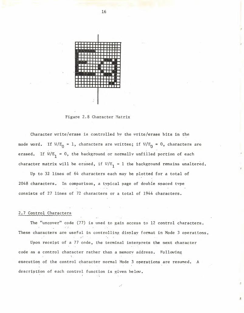
Four 64 charac t e r memories a r e provi ded in t he t e rmi na l. r-Emor i es t10
a nd M1 .a r e read- only memories ( RON ) which con tain the cha r a c ters s hm·.rn in
Tab l e 2 . 1. Memor ies t l ') and tl l
are ra ndom access memories (JW1)' each con-
taining 512 X 16 hit \vo r ds , t he conte nts of \vhich a r e loaded v i a Jl1ode 2 .
The con t en t s of _112 and "13
a re processed hv ~1ode OJ as 64 a rravs of 8 x 16
bit s each . The conte nts of. 8 consecutive addr esses a re disn l ayed as one
cha r ac t e r . All cha r ac t ers are dis plaved wit hin an R x 16 l'1~ trix as shO\m
i n Figure 2 . R. The t op thre e and t he bo ttom r ows oE t he ma trices fo r a l l
cha r acte r s f r om M0 and M1
are alwavs unfi l l ed .
•
16
Figure 2 . 8 Char ac t er ~1atrix
Character write/erase is cont r olled hv the ~rite/erase bits in the
mode word. If H/E0 = 1, cha r ac t e rs are Hritten ; if H/E0
= 0, cha r ac ters are
erased . If W/E1
= 0, the background or normallv unf illed portion of each
character matrix will be erase d, if H/E1
= 1 the backgr ound remains unaltered .
Up t o 32 lines of 64 characters each may be pl o tted for a to t al of
2048 characters . I n comp a r ison, a t ypi ca l page of double spaced tvpe
consis ts of 27 lines of 72 char ac ters or a t o t a l of 1944 characters .
2 . 7 Control Characters
The "uncover' ' code ( 77) is us ed t o gain access t o 12 control characte r s .
These characters are useful in cont rollin~ disn l ay fo rma t i n Mode 3 opera tions .
Upon receipt of a 77 code , the termina l interpre t s the nex t characte r
code as a control char acter r a the r t han a memorv add r ess . Follm.,ring , execu tion of the control charac t e r normal Hode 3 oper a t ions are res ume d. A
descript i on of each control fu nc t ion i s p,iven belm.t .
!

'ADDRESS (OCTAL)
0
1
2
3
4
5
6
7
~0
11
12
13
14
15
16
17
20
21
22
23
24
25
26
27
30
31
32
33
34
35
36
37
110 CHAR
:
a
b
c
d '
e
f
g
h
i
j
k
1
m
n
0
p
q
r
s
t ·
u
v
w
X ·
y
z
0
1
2
3
4
Ml CHAR
iF
A
B
c D
E
F
G
H .
I
J
K
L
M
N
0
p
Q
R
s T
u v w X
y
z -.. ~
.. ...
.
17
'ADDRESS (OCTAL)
40
41
42
43
: 44
45
46
47
50
51
52
53
54
55
56
57
60
61
62
63
64
65
66
67
70
71
72
73
74
75
76
77
MO CHAR
5
6
7
8
9
+ -
* I (
)
$
=
SP
' . . [
]
%
X
¢:
I
" I . ;
<
>
-?
~
..
UNCOVER
Tabl e 2 .1 Cha r acter Codes
Ml CHAR
t
+
+ +
"" 1:
fl
u
n
{
}
& , SP
I 0
-a
e 6
A.
~
tr
p
a
w
~
~
9
@
\ UNCOVER

18
Uncove r ( 77)
This code inst ructs the terminal t o obey the next char acter address as a -.
control f unction . If several un cove r codes a re sent in sequence, the first
non-uncover code wi l l b e treated as the con trol character .
3ackspace (10)
This char ac t er de c r eases by 8 the panel x address, i.e. , moves one
character position to t he lef t . A backspace over a displayed char ac ter does
no t erase the character.
Tab (ll)
This character increases by 8 the panel x address, i.e., moves one
cha r ac ter position to the right. A tab over a disp l ayed character does not
erase the charac t er .
Line Feed (12)
This character decreases by 16 the panel y address, i.e . , moves down one
ch ~ rac ter position . A line fe ed ove r a displayed character does not e rase the
charac t er .
Ve r L i c~ l Tab ( 13)
Th i s character inc reases by 16 the panel y add ress, i.e. , Moves up one
ch arac t e r position . A vertical tab over a displayed charac ter does not e rase
the charac t e r.
Fo rm Feed ( 14)
This character sets the panel address to the upper left corner (x = 0,
y :..: 496) . This is t he firs t character position on the t op line of the display.
No displayed data is erased i n th i s operation.
Carria ge Re turn (1 5)
Thi s cha rac ter cl~a rs (sets to 0) the panel x address and decreases by
16 th e y address. The ~sc reen address is t huti set to the first cha r ac ter
pos i Li o n nit t he line immediately belo\¥ the present line . Ho dis played

19
da t a is e r ased in t his oper a tion .
Supe r script (16 )
This char ac t er i ncreases the panel v address by 5 . Al l characters
received fo l lowing t his code appear as sh01-m in Figure 2 . 9 . This selec t ion
may be r emoved by r ec e i p t of a s ubscr ip t (17) code . No da t a is e r ased i n a
s uhs cript ope r a tion .
-~
! I
Figur e 2 . 9 Supersc r ipt Operation
Subscr ipt (17)
This characte r decreases by 5 the pane l v add r ess . All char ac t e r s
recei ved followi ng th is code appear as sh01m in Figure 2 . 9 . 1. Thi s
c ha racte r may be used to r emove a s uperscrip t se le c tion (16) and t he s upe r -
script code may be used to remove this se lecti on. No da t a i s e r aseci ir1 ,,
s upe r script operation .
•

20
II I lllll~
~
-~ ~
I i I
Figure 2.9 . 1 Subscrip t Operation
Se lec t M0
(20)
This code se l ects character memory 0. All succeeding characters t~ il l
be read from t he memory until receipt of a different memory select code .
Select M1
(21)
This code selects charac t e r memory 1. All succeedi ng characters wil l
be read from this memory unti l receipt of a di f ferent memorv se]ect code .
Select M2 (22)
This code selects charac te r memor y 2. All succeeding characters
will be read from tnis memory until receipt of a different memory select code.
Select M3
(23)
This code selects cha rac ter memnr y 3. All succeedin~ characters will
be read from this memory until receipt of a different memory select code .

•
21
2.8 Error Control
Contained 1 .. ri thin the terminal is a 7 bit Hord Count (IVC) register,
1vhich maintains a record of the nul'lher of non- NOP lvords received bv the
terminal. Ea ch time a non- HOP I·JOrd js tnm sferred i nto the terminal the
Word Count is incremented by 1 .
Upon receipt o f a lvord 11ith a parity e rror the teminal enters the
ABORT mode of operation . In this mode the terminal transmits the con tents
of the t-IC to the computer . The HC 111i 11 contain the a ddress of th e 1110 rd
containing the error.
Once in the ABORT mode the terminal Hi.ll ' refuse to accept any fu rther
information except for a LDM instruction ¥Tith bit 14 a " 1". Receipt of
this 1vord· lvill clear tl1e ABORT Rode and return ti-Je terminal to normal
operation. This met ~od · of error c onL~ol prevents the terminal from
processi.n ;; da ta i:1 th e wr ong mod e .i n the event an e rroneous mode lv o r d i s
r eceived .
22
CHAPTER 3 - TERMINAL GENERATED DATA
3.0 Data Sour ces
Data may be gene r a ted by any of four sour ces wi t hin the terminal or
by an external device connected to the external input channe~ . Internal
sources of data are :
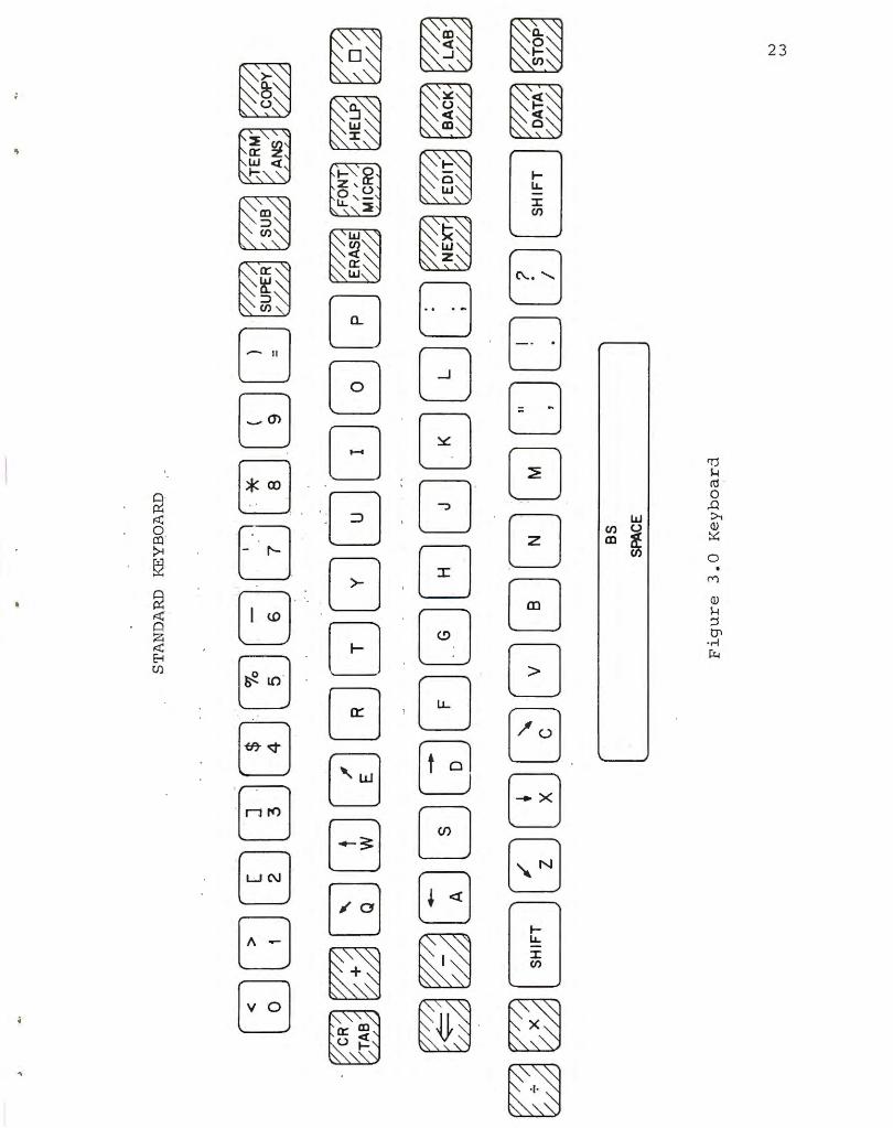
1. A 64 key keyboard shown in Figure 3 . 0 with the coding shovn
in Figure 3.1.
2 . The echo ce de. See LDE inst ruction in Section 2 .1.
, ~ . The Wo rd Count register. See Section 2 . 8 .
4. The Touch Panel . This is an optical i nput device which
permits the t erminal operator to enter data i nto the
computer by poin t ing at areas of olasma pane l with his
f inger .
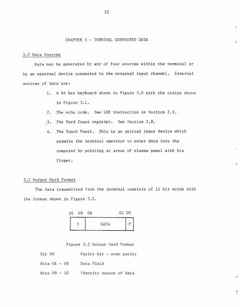
3. 1 Ou tout \.Jord Format
The data transmit ted f r om the t ermina l consis t s of 11 bit "YTords \vith
the forma t shmvn in Figur e 3 .2.
10 09 08 01 00
I DATA
Fi gure 3. 2 Output llord Format
Bit 00 Parity bit - even parity
Bits 01 - 08 Dn t a Field
Bits 09 - 10 Identity source of data
• I.
23
'\

054 000 001
056 002 003
161 167 004 005 006
145 162 164 171 007 010
165 011
151 133 020
157 160 021 022 033
063 064 065 074
DDDDDDDDDDDDDDDD 014 016 121 127 10 5 122 124 131 125
055 057 141 163 144 146 147 150 152 111
153 117 120
154 174 023
066 024
067 025 034
070 075
DDDDDDDDDDDDDDDD 015 017 101 123 104 106 107 110 112 113 114 134 026 027
053 052 . 172 170 143 166 142 156 155 177 176 175
~DBDDDDDDDDDDB 013 012 132 130 103 126 102 116 l15 137 136 135
140
[ l 100
NOTE: l. Each key h as two diffe r ent inputs. Th.e octal number below the box is the input '"hen :1 key is pressed singly (normal state), and the number above the box i s th e input lvhen the "Shift" key is held down as a key is pressed (shift state).
TI1e "Shift" key alone does not initiate input data transfer, but merely causes an addition of 040 (octal) to a normal input.
2. There is a total of 124 . different inputs.
3 . The input codes 036, 037 , 076, and 077 are not used.
Figure 3.1 Keyboard Coding
..
030 035 071 072
DO 031 032

25
The word fo rmats for each of the input sources is descr ibed below :
10 09 08 0 7 01 00
I 0 0 I 0 I I(EYBOARD DATA I p I 10 09 08 07
10 09 08
TOUCI! X
10 09 08
ECIIO CODE
OS 04
PANEL y
11 0 I EXTERNAL DATA
10 09 08
11 1 I 0 I !<ORO COUNT
10 09 08
01 00
01 00
01 00
01 00
h'he r e several terminals (up to 32) shar e a common l ink to the compute r
center the dr1ta is s e nt t o a multiplexor \vh i ch assigns a tennina l identity
code and adjusts the parity bit befor e transmit ting the data on t o t he
cente r. Tn thLs case , the data has the fo rmat s hm•n in Figure 3. '3 . Except
fo r the iden tity code , bit assig nments a r e the s ame as i n Figur e 3. 2 .
15
TEIUHNAL [OE:JTITY
11 10
DATA
Figure 3 . 3 Hultiplexed \Jo r d format
01 00