Embed Size (px)
Citation preview

The Plastic Bank Extruder
ASSEMBLY INSTRUCTIONS V1.0
2
Contents Safety Instructions……………………………………………………………………………………….. 3 Introduction………………………………………………………………………………………………… 4 Key Components………………………………………………………………………………………….. 4 Tools……………………………………………………………………………………………………….. 6 Assembly………………………………………………………………………………………………….. 7 Frame Assembly…………………………………………………………………………………… 7 Barrel Support Assembly………………………………………………………………………….. 10 Screw, Bearing and Drive Coupler Assembly………………………………………………… 15 Connecting The Barrel Support Assembly to the Frame………… ……………………….. 19 Mounting The Gear Box to The Frame ………………………………………………………... 21 Mounting The Motor to The Frame……………………………………………………………… 22 Attach Heater Bands……………………………………………………………………………… 24 Die Adapter and Die…………………………………………………………………………. 25 Attach Screw Case………………………………………………………………………………… 26 Mount Blowers…………………………………………………………………………………….. 27 Final Alignment of the Frame……………………………………………………………………. 28
Complete…………………………………………………………………………………………. 29
The Plastic Bank Extruder

3
Safety Instructions
IMPORTANT SAFETY AND WARNINGS
1. The extruder is an industrial extrusion machine and should only be built and operated by professionals with a strong knowledge of mechanical and electrical machinery.
2. The extruder is run by 120V/15A power, which can cause severe injury or death if handled incorrectly. 3. The extruder should only be installed in a large well-ventilated area to minimize inhaling of plastic
fumes 4. The electrical components are UL rated and comply with all North American Safety Regulations. 5. Only clean, filtered and dried thermo-plastic materials should be used in the extruder. 6. Never run the motor, when the machine has not reached the melting temperature of the residue plastic
inside the barrel. 7. Only adjust the motor speed when the motor is on and running. 8. The machine should never be left operating unattended. 9. Purge with low melt temperature polymer between every use.
The addition of protections is your responsibility. Safety can be improved by:
• An emergency stop button • Housing protection • A toxic fumes and smoke detector • Operators equipped with proper safety clothing: closed toed shoes, eye protection, and gloves
when operating the extruder
The Plastic Bank Extruder

4
Introduction The Plastic Bank Extruder is a continuous output single screw plastic extruder. That will allow the user to input thermo plastic material through a hopper and into the feed throat of the barrel. The design of our filament extruder, is a device that extrudes 3D printing filament up to 3mm in diameter. It can accommodate a variety of input polymer materials, however, it has been specifically designed to extrude virgin and recycled PET flakes. Throughout the project, various research and testing methods were conducted in the University of British Columbia’s chemical engineering laboratory. Within the lab we worked to measure PET viscosity data and extensively tested using UBC Pulp and Paper’s commercial extruder to develop the optimal extrusion processing conditions and design features. A ½ horsepower motor attached to a speed-reducing gearbox that rotates the extrusion screw drives the extruder. The extrusion barrel contains the screw and molten plastic that is temperature controlled by temperature sensors, heating bands, and cooling fans. The extrusion barrel also has an inlet opening and hopper at the top of barrel for polymer resin feeding. As the extrusion screw pushes the PET flakes forward to the end of the barrel, it simultaneously mixes and melts the plastic from the rotation of the screw and the heating of the heater bands. Once the plastic reaches the end of the barrel, an interchangeable die forms the final shape and diameter of the extruded filament. Key Components Motor and Drive: The motor and drive system have been selected to operate the extruder within the ranges of 25RPM to 60RPM continuously. In order to ensure ample torque, a 1/2 horsepower motor is driving the system. A DC motor controller is used to adjust speed at a range of 900-1800rpm at the motor output shaft. The motor is rigidly coupled to a 30:1 reduction worm drive gearbox. The gearbox output shaft is coupled to the extrusion screw via a flexible shaft coupler with replaceable rubber center. This style of coupler eliminates concerns about misalignment causing excess wear on the extrusion screw. The rubber center is also intended as a sacrificial component that will fail before the screw, gearbox, or motor in the case of jamming or excessive torque being applied. The maximum allowable torque for the rubber center is 51Nm.
The Plastic Bank Extruder

5
Screw and Barrel: Many home project filament extruder examples use small diameter auger screws to conduct their extrusion process, however the difficult nature of processing PET means these solutions would not produce useable product. We opted for a full size extrusion screw and barrel in order to ensure a high quality filament would be produced. The screw has a L:D ratio of 30:1, and a compression ratio of 2:1, which are well suited for processing PET plastic. The screw is made of nitrided 4140 alloy steel to ensure longevity, corrosion, and wear resistance. The barrel is made of alloy 38CrMoALA steel. Heating and Cooling: The bulk of the heat generated in the extrusion process is from the screw’s rotary motion. When the motor is performing at rated condition, the screw generates about 85% of the heat required to melt the plastic to a composition that enables smooth flow through the barrel. Three Heating bands that are controlled by voltage pulse ON/OFF controllers generate the remainder of the heat to enable better steady state operation. Die Adapter and Die: We designed a die adapter that would accommodate a wide range of low cost interchangeable dies that can be separately bolted on to the end of the die adapter. The die adapter is fastened onto the external thread of the extrusion barrel channeling the flow down to a 3 mm diameter, the maximum diameter of commercial grade filament. Framing System: The framing system chosen by the team utilizes highly versatile and available T-slot aluminum bars to align components. We have reinforced regions with aluminum plates where torsion loads may occur to accommodate for the T-slot flexibility. The mounting of the barrel required additional structures to hold it in place and properly aligned. Multiple concentric discs are pinned together with tight tolerances to hold a bearing that constrains the extrusion screw to the center of the barrel. The same discs are interlocked with side supports to fasten the assembly to the T-slot frame. Power Control System: The device is designed to work with the Canadian single-phase standard residential AC power (120 VAC, 60 Hz, Max 15 Amp Current draw). The electronically powered components on board the device are the motor and motor drive, the temperature controllers, solid-state relays, the heating bands, and the cooling fans. It should be noted that fuses have been put in place as a safeguard to ensure that the user and electrical components are protected from a large amperage draw over the rated 15 Amps. The control box will allow the user to set desired temperatures for three heating zones, allows the user to manually switch off any heating bands as an added safety, adjust the speed of the motor for optimum performance.
The Plastic Bank Extruder

6
Tools
• Band saw • Water jet cutter • 3d printer • Drill press • Drill • Grinder • Thread tap and die set • Soldering Iron • Metal Lathe • Mallet • Hand tools (screw drivers/wrench set/hex set) • Wire cutters • Crimp tools
The Plastic Bank Extruder

7 The Plastic Bank Extruder
Assembly 1. Frame Assembly
• 2 x 1050mm Aluminum extrusion • 4 x 265mm Aluminum extrusion • 2 x 240mm Aluminum extrusion • 2 x 160mm Aluminum extrusion • 10 x 90mm Aluminum extrusion • 12 x T-shaped bracket SET • 2 x L-shaped bracket SET
1050mm extrusion
160mm extrusion
265mm extrusion
90mm extrusion
240mm extrusion

8
Frame Assembly Continued
The Plastic Bank Extruder
Use T-Brackets with nut and screw SET to connect extrusions

9
Top View of Frame Assembly
Back View of Frame Assembly
Frame Assembly Continued
The Plastic Bank Extruder
2 x L-Bracket
12 x T-Brackets

10
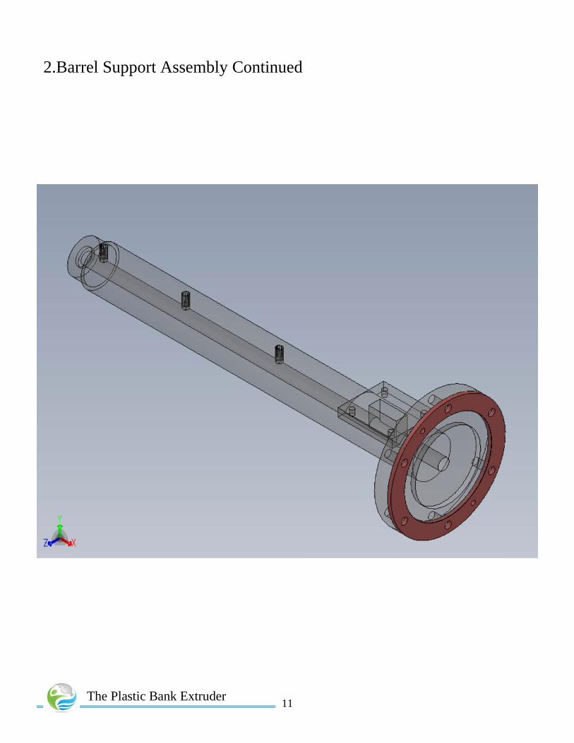
2.Barrel Support Assembly
• 1 x Flange mate • 1 x Main Bracket • 2 x Support stands • 6 x Spacer • 6 x M12x70mm hex bolts • 6 x M12 nuts
The Plastic Bank Extruder
Support Stand
Main Bracket Spacer
Flange Mate
11
2.Barrel Support Assembly Continued
The Plastic Bank Extruder

12
Barrel Support Assembly Continued
The Plastic Bank Extruder
Spacers

13
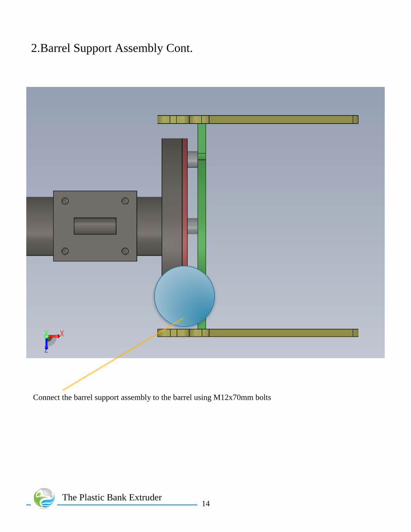
2.Barrel Support Assembly Cont.
Use a mallet to insert the support stands into the main bracket
The Plastic Bank Extruder
14
2.Barrel Support Assembly Cont.
The Plastic Bank Extruder
Connect the barrel support assembly to the barrel using M12x70mm bolts

15
3.Screw, Bearing and Drive Coupler Assembly
• 1 x Screw • 1 x Shaft Collar • 1 x Bearing • 2 x Shaft Coupling Hub • 1 x Rubber Center • 1 x Bearing Backing Plate • 4 x M5x20mm bolts • 4 x M5 nuts • 4 x washers
The Plastic Bank Extruder
Screw
Drive Coupler Assembly
Shaft Coupler
Bearing
Bearing Backing Plate

16
Screw, Bearing and Drive Coupler Assembly Continued
The Plastic Bank Extruder
Screw tip should align with the end of the barrel

17
Screw, Bearing, and Drive Coupler Assembly Continued
The Plastic Bank Extruder
Mount the bearing backing plate to the main bracket using M5x20mm bolts
Spacers between the main bracket and the bearing backing plate

18
Screw, Bearing, and Drive Coupler Assembly Continued
The Plastic Bank Extruder

19
4.Connecting The Barrel Support Assembly to The Frame • 1 x Frame assembly • 1 x barrel support assembly • 10 x Insertion short nuts • 10 x M5x14mm Socket head cap screws
The Plastic Bank Extruder
• Lightly fasten the socket head cap screws with insertion short nuts on to the barrel support stands
• Slide the barrel assembly on to the frame, aligning the nuts to the groves of the aluminum extrusions
• Once all nuts are in the frame, tighten the nuts to secure the barrel assembly on to the frame

20
Connecting The Barrel Support Assembly to The Frame
The Plastic Bank Extruder

21
5. Mounting the Gear Box to the Frame
The Plastic Bank Extruder
• 1 x Gearbox spacer • 1 x Gear Box • 4 x M5x8mm screws • 4 x M5 extrusion nuts • 4 x ½’’ UNC screws • 4 x ½’’ hex nuts
Use M5 screws and extrusion nuts to mount spacer to the frame
Use ½’’ UNC Hex cap screws to mount speed reducer to the spacer
Gear-box Spacer
30:1 Speed reducing worm gear

22
6. Mounting the Motor to the Frame • 4 x Cylinder spacer • 1 x Motor Spacer • 1 x ½ hp Motor • 1 x Rigid Coupler • 4 x M5x35mm screws • 4 x M8x30mm Screws • 4 x extrusion nuts • 4 x M5 hex nuts
The Plastic Bank Extruder
M5x35mm M8x30mm

23
6. Mounting the Motor to the Frame Continued
The Plastic Bank Extruder
Rigid Coupler connects motor shaft to the speed reducer

24
7. Attach Heater Bands • 3 x Heater bands
The Plastic Bank Extruder
Thermo couple holes

25
8. Die Adapter and Die • 1 x Die Adapter • 1 x Die • 4 x M5x14mm
Screws
The Plastic Bank Extruder
5mm Threaded holes

26
9. Attach Screw Case • 1 x Screw Case
The Plastic Bank Extruder
The sheet metal screw case will sit in the groves of the aluminum extrusions

27
10. Mounting Blowers • 2 x Blowers • 8 x M5X8mm screws • 8 x M5 hex nuts
The Plastic Bank Extruder

28
11. Final alignment of the Frame • 10 x Frame end caps • 4 x reversal bracket SET(sets include required nuts and screws) • 2 x reversal bracket#2 SET
Once all components are correctly aligned securely tighten all brackets and frame assembly. Assure alignment is correct before processing any plastic
The Plastic Bank Extruder