Embed Size (px)
Citation preview

The new Divertor Tokamak Test facility
Raffaele Albanese1, Flavio Crisanti2, Piero Martin 3, Aldo Pizzuto2
and DTT Team
1Università degli Studi di Napoli Federico II and Consorzio CREATE, Napoli, Italy
2ENEA, Dipartimento Fusione e Sicurezza Nucleare, Frascati, Italy
3Università degli Studi di Padova and Consorzio RFX, Italy
CERN, Geneva, 13 September 2019

Outline
1. EU Roadmap toward fusion electricity
2. Introduction to the DTT Project
3. DTT design status
4. Planning and conclusions
2
Outline
1. EU Roadmap toward fusion electricity
2. Introduction to the DTT Project
3. DTT design status
4. Planning and conclusions
3

4
FUSION: What
E = m c2
Advantages of fusion:
• Abundance of fuel
• Small amount of fuel needed
for reactor conditions
• No pollution
• No greenhouse effect
• No direct nuclear waste
• No risk of severe accidents

5
FUSION: What
Conditions needed for fusion
reactions
• EM & nuclear forces. Potential
barrier.
• At the very high temperatures
needed for fusion the gas is fully
ionized and is a very good conductor:
plasma (4th state of the matter).
• Magnetic confinement
Larmor radius
~ 50 000 000 °C
Courtesy of
CERM.UniFI
Courtesy of CCFE, JET
EAST (Hefei,China) 100 M °C Nov 2018
6
FUSION: How
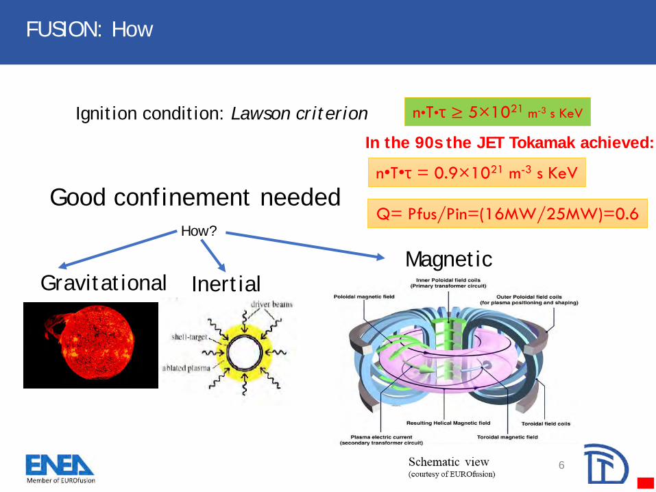
Ignition condition: Lawson criterion n•T•τ ≥ 5×10²¹ m-3 s KeV
GravitationalMagnetic
Good confinement needed
How?
Inertial
In the 90s the JET Tokamak achieved:
n•T•τ = 0.9×10²¹ m-3 s KeV
Q= Pfus/Pin=(16MW/25MW)=0.6

7
Fusion electricity: when
Further Step: DEMO, 2050
(Demonstration Fusion Power Plant )
In the 90’s the JET provided a fusion gain Q>0.6.(16 MW of nuclear fusion power (D-T reactions,with 25 MW of input heating power)
Next Step: ITER (2015)Mission of ITER: to improve Q, by increasingmagnetic field, plasma current and machine size.• OUT: Pfus=500 MW from• INPUT Pin=50 MW (Q10).
Which are the main challenges to face
along the roadmap toward the fusion
power plant?
Military weapon Commercial reactor
Fission 1945 1956-57
Fusion 1951-52 ?

8
EU Fusion Roadmap: Missions
The European fusion community identified eight important
missions on the path towards fusion electricity:
1) Plasma regime of operation
2) Heat-exhaust system3) Neutron resistant materials
4) Tritium self-sufficiency5) Implementation of intrinsic safety features of fusion6) Integrated DEMO design and system development7) Competitive cost of electricity8) Stellarator
“If alternate exhaust strategies were to be only explored in the event of ITER showingthat the baseline exhaust strategy cannot be extrapolated to DEMO, the realisation offusion would be delayed by at least 10 years…. for the alternative approaches theextrapolation from proof-of-principle devices to DEMO based on modelling alone isconsidered too large. If a promising alternative concept emerges, a divertor optimised forthe concept will be implemented in the Italian Divertor Test Tokamak (I-DTT) facility as ajoint European collaboration. ”Tony Donné, William Morris, et al., “European Research Roadmap to the Realisation of FusionEnergy A road map to the realisation of fusion energy” www.euro-fusion.org/fileadmin/user_upload/EUROfusion/Documents/2018_TopLevel_Roadmap.pdf
EU Fusion
Roadmap

9
Fusion Roadmap: plasma edge

10
Fusion Roadmap: the heat exhaust challenge
Two-point Modeling of the Divertor SOLP. Stangeby, Inst. for Aerosp. Studies, Toronto Univ., Ont., Canada

11
T.Eich. et al. NF 53 (2013) 093031
From a multimachine scaling of the upstream heat flux width the SOL power flow decay length scales as:
for ITER and DEMO:
𝒒 ≈ 𝟏𝒎𝒎, P/R ≈ 15 MW/m
q Bpol-1 and does not depend on R
Power flux 𝑞𝜗 = Τ𝑃 2𝜋𝑅𝜆𝑞
𝑃
𝑅
Effective surface 1-2 m2
Power flux: tens of MW/ m2
Fusion Roadmap: SOL (Scrape-Off Layer)

12
Fusion Roadmap: Possible solutions for heat exhaust
• Plasma facing components to cope with very large power fluxes
– 10-20 MWm-2 achieved
• Geometry + plasma physics
Remove plasma
energy before it
reaches PFCs →
radiation
Alternative configurations (courtesy of EPFL)
Strike point sweeping
(courtesy of JET)
Innovative
materials
(Liquid
Metal
PFCs)
Outline
1. EU Roadmap toward fusion electricity
2. Introduction to the DTT Project
3. DTT design status
4. Planning and conclusions
13

What is DTT?
DTT = Divertor Tokamak Test facility is:
• An Italian 6 T, 5.5 MA superconducting tokamak
• Under final design
• To be built in ENEA Frascati Research Centre
• Within the European roadmap to the realization
of fusion energy
• To study the power exhaust problem in:
o An integrated environment
o DEMO relevant conditions
14
Great national and international interest:
- >150 M€ from national funds
- 60 M€ from EUROfusion
- 250 M€ EIB loan for this research infrastructure
- EU and int’l cooperations activated

15
DTT: Boundary conditions in the design
Physics parameters relevant for ITER/DEMO
and core – edge integration
Technology choices relevant for DEMO

How? The recipe: parameters + technology
DTT ITER EU DEMO
R (m) 2.14 6.2 9.1
a (m) 0.65 2 2.93
A 3.3 3.1 3.1
Ip (MA) 5.5 15 19.6
B (T) 6 5.3 5.7
Heating Ptot (MW) 45 120 460
Psep /R (MW/m) 15 14 17
Pulse length (s) 95 400 7600
Flexibility and DEMO relevant technologies
16

Why DTT?
Power exhaust problem solved by:
1. Plasma facing components technology -> max heat
flux presently limited to 10-20 MW/m^2
2. Geometry + Plasma shape
3. Impurity seeding to increase radiation
4. Liquid metals
DTT aims at providing a key integrated environment,
relevant to DEMO, where all the previous approaches
can be tested.
17

How? Some history…
• July 2015: DTT Project proposal• Apr 2018: Frascati selected as DTT site• July 2018: 1st Design Review Meeting of major components• End 2018: Launched first call for tender procedure (for SC strands)• End 2018: Recruitment of ENEA personnel started• Mar 2019: 2nd Design Review Meeting • Apr 2019: DTT Interim Design Report• June 2019: 3rd Design Review Meeting • June 2019: Availability of EFSI portfolio guarantee for 250 M€ EIB loan• Aug 2019: Partial award of SC strand contract• Sept 2019: Establishment of DTT Consortium
2015 2017 2018
30th SOFT
2019
18

Outline
1. EU Roadmap toward fusion electricity
2. Introduction to the DTT Project
3. DTT design status
4. Planning and conclusions
19
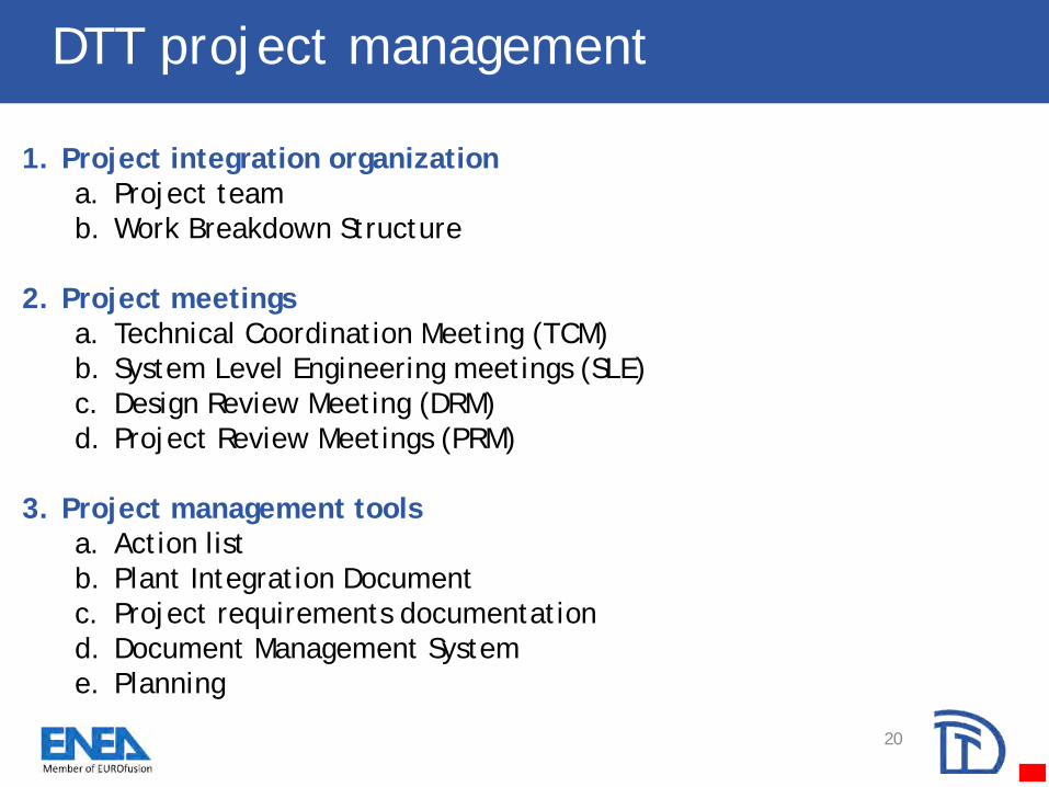
1. Project integration organization
a. Project team
b. Work Breakdown Structure
2. Project meetings
a. Technical Coordination Meeting (TCM)
b. System Level Engineering meetings (SLE)
c. Design Review Meeting (DRM)
d. Project Review Meetings (PRM)
3. Project management tools
a. Action list
b. Plant Integration Document
c. Project requirements documentation
d. Document Management System
e. Planning
DTT project management
20
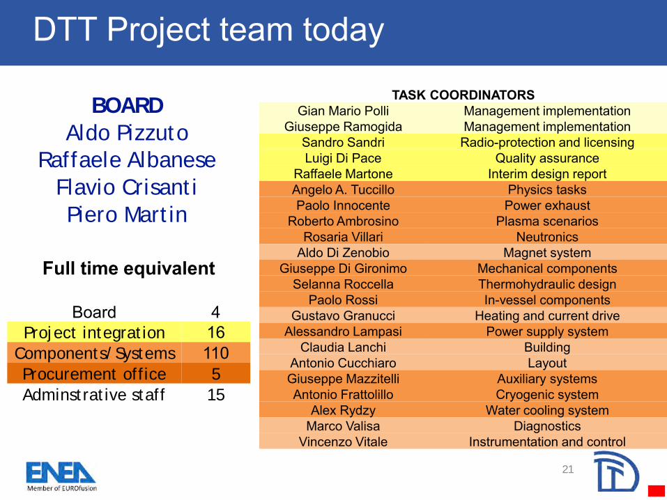
DTT Project team today
BOARD
Aldo Pizzuto
Raffaele Albanese
Flavio Crisanti
Piero Martin
TASK COORDINATORSGian Mario Polli Management implementation
Giuseppe Ramogida Management implementationSandro Sandri Radio-protection and licensingLuigi Di Pace Quality assurance
Raffaele Martone Interim design reportAngelo A. Tuccillo Physics tasksPaolo Innocente Power exhaust
Roberto Ambrosino Plasma scenariosRosaria Villari Neutronics
Aldo Di Zenobio Magnet systemGiuseppe Di Gironimo Mechanical components
Selanna Roccella Thermohydraulic designPaolo Rossi In-vessel components
Gustavo Granucci Heating and current driveAlessandro Lampasi Power supply system
Claudia Lanchi BuildingAntonio Cucchiaro LayoutGiuseppe Mazzitelli Auxiliary systemsAntonio Frattolillo Cryogenic system
Alex Rydzy Water cooling systemMarco Valisa Diagnostics
Vincenzo Vitale Instrumentation and control
Full time equivalent
Board 4Project integration 16
Components/Systems 110Procurement office 5
Adminstrative staff 15
21

DTT Project organization in perspective
22

DTT layout: site – ENEA Research Center
23
ENEA C.R. Frascati
23

DTT layout: site – torus hall
28 m
24
DTT layout: Neutronics
25
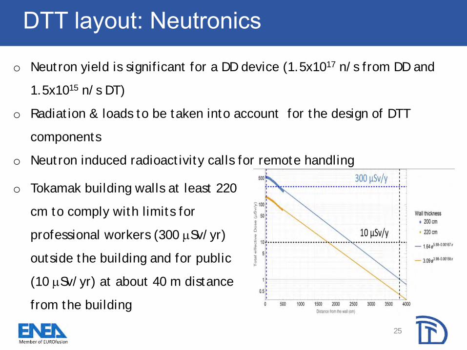
o Neutron yield is significant for a DD device (1.5x10¹⁷ n/s from DD and
1.5x10¹⁵ n/s DT)
o Radiation & loads to be taken into account for the design of DTT
components
o Neutron induced radioactivity calls for remote handling
o Tokamak building walls at least 220
cm to comply with limits for
professional workers (300 Sv/yr)
outside the building and for public
(10 Sv/yr) at about 40 m distance
from the building

DTT layout: DTT machine at a glance
~11 m
~11 m
Item TF CS PF VV Cryostat NBI Total
Mass [ton] 270 45 126 153 302 80 ~ 1000
26
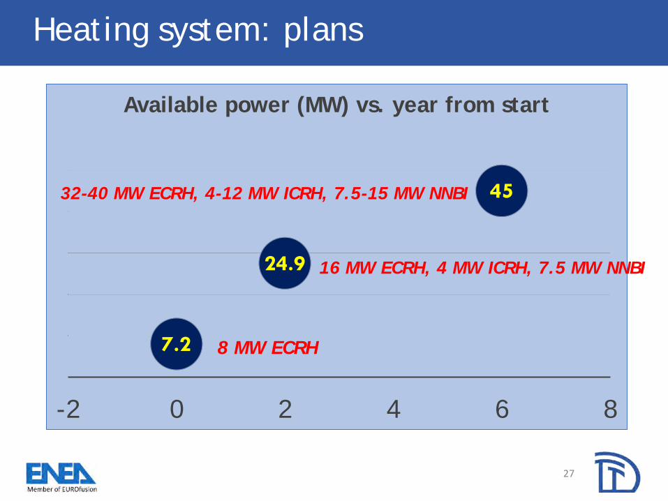
7.2
24.9
45
-2 0 2 4 6 8
Available power (MW) vs. year from start
8 MW ECRH
16 MW ECRH, 4 MW ICRH, 7.5 MW NNBI
32-40 MW ECRH, 4-12 MW ICRH, 7.5-15 MW NNBI
27
Heating system: plans
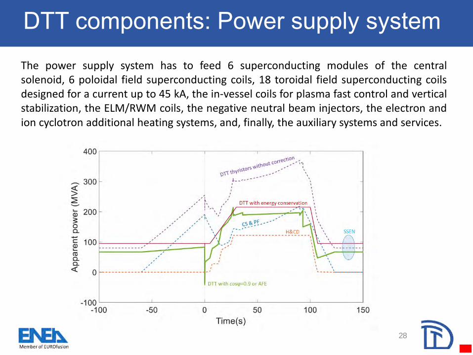
DTT components: Power supply system
28
The power supply system has to feed 6 superconducting modules of the centralsolenoid, 6 poloidal field superconducting coils, 18 toroidal field superconducting coilsdesigned for a current up to 45 kA, the in-vessel coils for plasma fast control and verticalstabilization, the ELM/RWM coils, the negative neutral beam injectors, the electron andion cyclotron additional heating systems, and, finally, the auxiliary systems and services.

Basement
Main Cylinder
Top Lid
29
Major diameter at equatorial section ~11.2m
Maximum height including basement ~11 m
Structural MaterialSA-240
304LN
Operational pressure (Vacuum) 10-3 Pa
Design temperature of cryostat wall 293 K
Thickness of the cryostat walls 30 mm
Thickness of the external ribs 25 mm
Estimated Mass of CV main cylinder ~66 tons
Estimated Mass of CV top lid ~16 tons
Estimated Mass of CV basement ~220 tons
DTT Cryostat

Magnet system: overview
18 Toroidal Field coilsNb3Sn Cable-In-Conduit Conductors
5 Double-Pancakes (3 regular + 2 side)
6 Central Solenoid module coilsNb3Sn Cable-In-Conduit Conductors
6 independent modules
6 Poloidal Field coils4 NbTi Cable-In-Conduit Conductors
2 Nb3Sn Cable-In-Conduit Conductors
6 independent modules
Present design based on proven
and reliable technologies
6 In-vessel Cu coils
Possible future upgrade: innovative
additional HTS coil to be inserted in the CS
→ 10% flux increase + test bed for next
generation magnets30

31
Double-walled vacuum vessel
Shell Thickness (inboard) 15 mm
Shell Thickness (outboard) 15 mm
Ports Thickness 25 mm
Ribs thickness 10 mm
Volume VV 75 m3
Material AISI 316-L(N)
Weight of main vessel body 36900 kg
Operating Temperature of the
VV (max)60 °C
Baking temperature of the VV
(max)110 °C
~ 4 m
~ 2.2 m

DTT components: In-vessel components
32
Design requirements compatibility:
• liquid lithium divertor (closed cycle)
• remote handling system
• In-vessel magnetic diagnostics
• In-vessel control coils
• DEMO Materials
• electromagnetic loads
FW inboard module: 2 modules per VV
sector for RH limitations
FW outboard: plane modules plus a top part
per VV sector for RH limitations and loads

DTT divertor
33
DTT makes it possible to test different divertor
concepts: both conventional and advanced solutions:
The challenge is that the EUROfusion
decision on the first divertor concept is
planned around 2023 and we should be so
flexible to incorporate it inside the DTT vessel

DTT divertor: agreement with EUROfusion
34
• The project milestones have been agreed together with
the EUROfusion consortium
• Eurofusion will provide divertor concept and plasma
scenario to adopt in the first day of operations at the
beginning of 2023.
• DTT is being designed allowing the necessary flexibility to
allocate the different options from now (reference
scenario is SN and reference divertor is the solid one)

Plasma scenarios: DTT flexibility
The facility will offer sufficient flexibility to incorporate
the best candidate divertor concept even at a later stage
of its realization, on the basis of the EUROfusion studies
carried out in present tokamaks involved in the PEX
activities (around 2022-2023).
Double NullIpl=5 MA
SnowflakeIpl=4.5MA
X-divertorIpl=4.5MA
Neg. triangularityIpl=5MA
Double Super-XIpl=3MA
Single NullIpl=5.5 MA
35

1 1.5 2 2.5 3 3.5-2
-1.5
-1
-0.5
0
0.5
1
1.5
2Negative Triangularity at 5MA
1 1.5 2 2.5 3 3.5-2
-1.5
-1
-0.5
0
0.5
1
1.5
2
Plasma scenarios: DTT flexibility
DTT poloidal field coils system allows 3.5 MA double null with negative triangularity 𝜹 = −𝟎. 𝟑𝟖
The space available inside the TF coils allows optimization of the first wall, the stabilizing plates and the vessel shells
Neg. triagularity
Ipl=5MA
Double Neg. triagularity
Ipl=3.5MA
𝜹 = −𝟎. 𝟏𝟑 𝜹 = −𝟎. 𝟑𝟖
Significant range for I-mode operationwhile avoiding H-mode
36

Outline
1. EU Roadmap toward fusion electricity
2. Introduction to the DTT Project
3. DTT design status
4. Planning and conclusions
37

How? Planning of main components
Design completion
Tender phase
Manufacturing
38

DTT management: Main procurements and services
39
1.Superconducting Magnets:Strands: Nb3Sn and NbTi *Cables**Magnets (coils+casings)**External structure
2. Vessel/In-Vessel:Vacuum ChamberFirst WallDivertor
3. Power Supplies:CS, PF, TF & protection systemsAdditional heatingAuxiliariesDistribution systems
4. Heating system: Ion CyclotronElectron CyclotronNeutral Beam Injector
5. Cryocooler
6. Control & data acquisition
7. Remote maintenance
8. Buildings
9. Assembly
* Call for nomination + prequalification + call for tender + evaluation phases concluded:2 lots out of 4 awarded
** Info day for the procurement of the DTT toroidal field magnets, Frascati, 8 Oct. 2019,in view of the call for tender procedures to be started soon

DTT management: Next steps
40
• Apr 2018: Frascati selected as DTT site
• July 2018: 1st Design Review Meeting of major components
• End 2018: Launched first call for tender procedure (for SC strands)
• End 2018: Recruitment of ENEA personnel started
• Mar 2019: 2nd Design Review Meeting
• Apr 2019: DTT Interim Design Report
• June 2019: 3rd Design Review Meeting
• June 2019: Availability of EFSI portfolio guarantee for 250 M€ EIB loan
• Aug 2019: Partial award of SC strand contract
• Sept 2019: Establishment of DTT Consortium
• End 2022: 1/3 of the machine completed
(6 TFCs, 3 VV sectors, cryostat base, main hall, ...)
• 2022-2023: Decision on divertor configuration (PEX)
• 2022-2025: Assembly and commissioning
• End 2025: First experimental plasma: 3T, 2 MA
• 2025 − : Operations

Concluding remarks
• From 2015 to 2018 the DTT roles & objectives fixed and baseline provided
• From October 2018 organization set-up
• In September 2019 DTT Consortium established
• Concerning design activity:
– From September 2018 ENEA Frascati chosen for the DTT site
– Design integration of all components is progressing in accordance with
priorities defined by the detailed planning
– Toroidal Field coil design almost completed: tender expected end-2019
• First plasma planned end-2025
• DTT open to collaboration (cooperation agreements already established
with EUROfusion as well as outside EU)
• For further info see Interim Design Report (“Green book”):
www.dtt-project.enea.it/downloads/DTT_IDR_2019_WEB.pdf
41
Further information
42
For further information:
www.dtt-project.enea.it

Extra slides
• EXTRA SLIDES
43
DTT divertor: agreement with EUROfusion
44
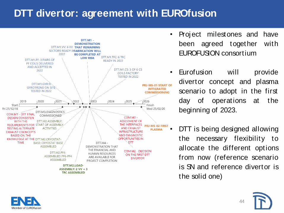
• Project milestones and have
been agreed together with
EUROFUSION consortium
• Eurofusion will provide
divertor concept and plasma
scenario to adopt in the first
day of operations at the
beginning of 2023.
• DTT is being designed allowing
the necessary flexibility to
allocate the different options
from now (reference scenario
is SN and reference divertor is
the solid one)

DTT : Toroidal Field coils
45
- CICC operating current: 44.8 KA
- Bpeak: 11.9 T- Double pancake-winding: 80 turns
(3 Regular pancakes 9x2 and 2 Side panc. 9x1–4x1)
- Max. hydraulic length: 110 m
- Cable: 504 / 144 S.c./Cu wires
- Tmargin > 1.4 K
- Jacket: 2 mm 316 LN
- Turn insulation: Fiber-glass + resin
Overall TF energy: 2
GJ
L (1 TF coil): 41 mH
TF coil height ≈ 6 m
TF coil width ≈ 3.2 m
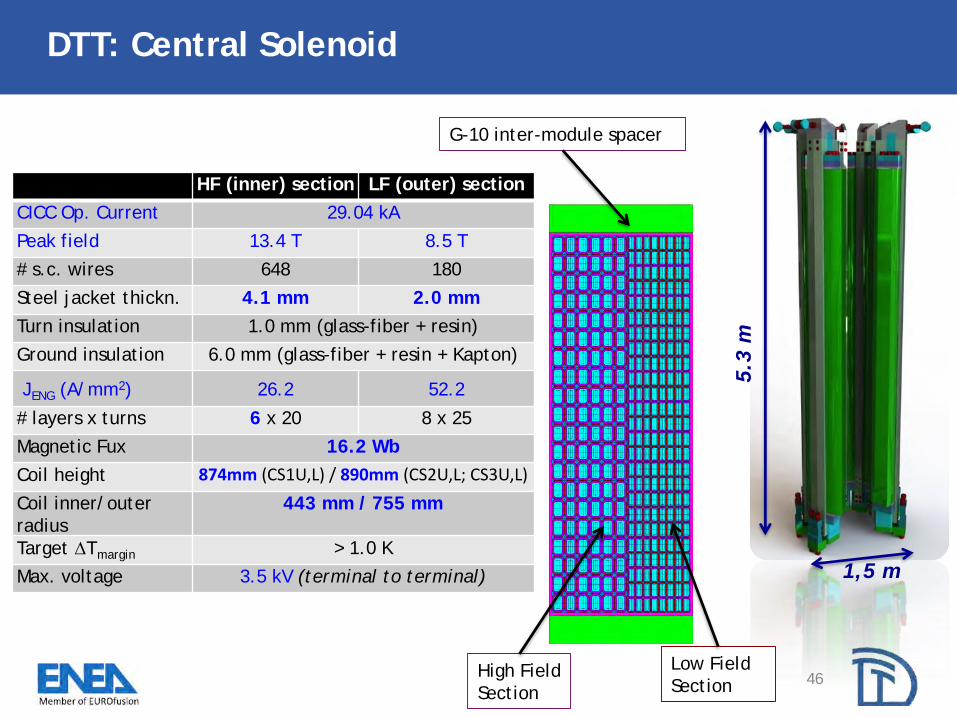
HF (inner) section LF (outer) section
CICC Op. Current 29.04 kA
Peak field 13.4 T 8.5 T
# s.c. wires 648 180
Steel jacket thickn. 4.1 mm 2.0 mm
Turn insulation 1.0 mm (glass-fiber + resin)
Ground insulation 6.0 mm (glass-fiber + resin + Kapton)
JENG (A/mm2) 26.2 52.2
# layers x turns 6 x 20 8 x 25
Magnetic Fux 16.2 Wb
Coil height 874mm (CS1U,L) / 890mm (CS2U,L; CS3U,L)
Coil inner/outer
radius
443 mm / 755 mm
Target Tmargin > 1.0 K
Max. voltage 3.5 kV (terminal to terminal)
DTT: Central Solenoid
46
5.3
m
1,5 m
High Field
Section
Low Field
Section
G-10 inter-module spacer

DTT: Poloidal Field coils
47
L. Muzzi - The DTT Magnet System – EUCAS 2019 –
Glasgow
PF1
PF2
PF3
PF4
PF5
PF6
COIL PF1/6 PF2/5 PF3/4
Bmax (T) (input data) 9.1 4.4 5.4
# turns (radial x
vertical)20 x 18 10 x 16 14 x 14
Iop max (kA) 28.3 27.1 28.6
ΔTmargin (Top: 4.5K) 1.8 1.8 1.7
Hydraulic length (m) 178 193 381
L (H) 0.454 0.298 0.690
Vmax (V) 2150 1350 3290
Weight (ton) 15 16 28
Delay / discharge const. 1.5 s / 6 s
CICC dimensions (mm) 23.4 x 28.3 26.4 x 27.7 26.4 x 27.7
Jacket thickness (mm) 3.0 3.0 3.0
Central channel (in/out) 5 / 7 mm 5 / 7 mm 5 / 7 mm
# SC (1.9 Cu/noCu) /
Cu strands; 0.82 mm
180 (Nb3Sn) / 216
162 (NbTi) / 324
324 (NbTi) / 162
PF Double-
pancake
winding and
joint boxes

1. Project integration organization
a. Project team
b. Work Breakdown Structure
2. Project meetings
a. Technical Coordination Meeting (TCM)
b. System Level Engineering meetings (SLE)
c. Design Review Meeting (DRM)
d. Project Review Meetings (PRM)
3. Project management tools
a. Action list
b. Plant Integration Document
c. Project requirements documentation
d. Document Management System
e. Planning
How? DTT project management
48

49
Tokamaks are among the most complex machines ever conceived by
the mankind:
• Coexistence of temperatures close to highest and lowest values
in the universe
• Nuclear environment, high magnetic fields, vacuum
requirements, large heat fluxes
• All fields of science and engineering involved: large teams
needed
Wesson J., “Tokamak”, Oxford University Press 2011 – 4th Edition
Tokamaks
Schematic view(courtesy of EUROfusion)
FUSION: How

50
FUSION ELECTRICITY: When
Courtesy of EUROfusion
Military weapon Commercial
reactor
Fission 1945 1956-57
Fusion 1951-52 ?


![Performance assessment of tightly baffled long leg ... · X-point Target Divertor implemented in ARC [4] ARC divertor challenge: reactor-scale power in compact machine. • ARC divertor](https://img.dokumen.tips/doc/110x75/5e84395e19095c15aa76cb7d/performance-assessment-of-tightly-baffled-long-leg-x-point-target-divertor-implemented.jpg)