Embed Size (px)
Citation preview
. .
INSTRUCTHJN BOOKLET No. l ()
THE MORSE
KEYBOARD PERFORATOR
MODEL No. lJ.
CREED
!1 CREED & CO. LTD.
TELEGRAPH HOUSE
CROYDON
CONTENTS
Page
GENERAL 3
OPERATION 5
DISMANTLING AND ASSEMBLING 11
ADJUSTMENTS 20
LUBRICATION CHART 22
POSSIBLE FAULTS AND RECTIFICATION 23
MAINTENANCE 24
LETTER COUNTER 25
TOOLS AND ACCFSSORrn.S 28
THE MORSE
KEYBOARD PERFORAT OR
MODEL No. 9.
INSTRUCTION BOOKLET
No. 16
(Re-issued September, 1945)
(Superseding Boohlet issued May, 1943)
CREED & CO. LTD.,
TELEGRAPH HOUSE,
CROYDON.
Telegrams: Cables: "CREDO, TELEX, CROYDON." "CREDO, CROYDON."
Telephone: CROYDON 2121 (6 lines).
Telex No.: CROYDON TELEX 1082.
2
CONNFCTION �'LOCll
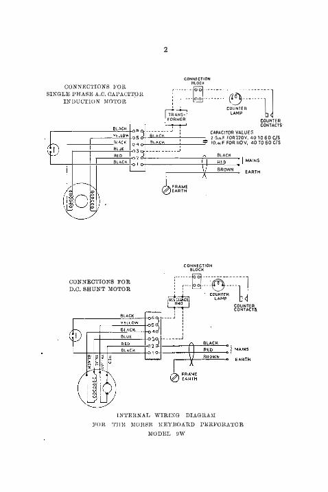
CONNECTIONS FOR SIKGLE PHAS1' A.O. CAl'AUlTOR
INDUC'l'lON MOTOlt ··-----ld :.:·_�: �� . .
�::::t--l • 1 couNrr:n GANS- LAMP
FORMEf:l
CAPACfTOR VALUES
COUNTER CONTACTS·
BLACK 2·5.«F FOR220V, 4010 60 C/S fO.-«F FOR lfOV, 40 TO 60 C/S
RED BLA..CK
BLACK
o+--------f+-�RE�D�-) MAINS
FRAME EARTH
CONNECTION BLOCI-<
BROWN EARTH
CONNECTIONS FOR D.O. SHUNT :\!OTOR
· :·--:_-_:a.��-:6�:�_---1 :�: . COUNTER l I �HANCl LAMP b <j L..,Ul.u! COUNTER I I CONT.ACTS.
BLACK r, � ---- j ! �--Y_E�L_L_OW_-t-O S
: �-f----'B�L�A�C�K-+<>4 : BLUE ______ J
RED BLACi<:
BLACK
lNTEI\NAL WIRIXG DIAGHA,\I
FO!t '.I'll 1': MOHSR KEYJJOAHD l'1'1U'ORATOR
MODEL DW
3
THE CREED MORSE KEYBOARD
PERFORATOR
This Perforator prepares tape for controlling all types of Automatic Wheatstone or Cable Code Tape Transmitters.
It consists of a motor driven punching head under the control of a Keyboard which can be operated up to a speed of approximately 100 w.p.m.
. When it is required to perforate tape that is to be used for automatic transmission to stations employing Morse Page Printers, an End of Line Indicator is fitted.
The machine is operated in a similar manner to a typewriter. Depression of any key controls a number of combination bars and causes a combination of holes to be punched in a paper tape. After being punched the tape is fed out of the punch block, thus providing blank tape in which the next character can be perforated.
Physical Data.
Weight Length Width Height
Power Requirements.
38 lbs. 19 ins. 11 ins. 11 � ins.
Any commercial A.C. or D.C. supply or 24 v. D.C. Power consumption A.C. approx. 80 W.
Construction.
D.C. ,, 55 W.
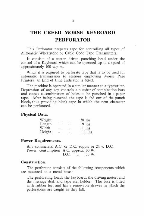
The perforator consists of the following components which are mounted on a metal base :-
The perforating head, the keyboard, the driving motor, and the message desk and tape reel holder. The base is fitted with rubber feet and has a removable drawer in which the perforations are caught as they fall.
4
5
The. perforator can be supplied mounted on a wooden base with a wooden message rack and horizontal tape reel. In this model the motor is mounted on the wooden base and not on the frame of the perforator.
To Feed the Tape.
Place the tape on the wheel so as to unwind in an anti-clockwise direction. Feed ·it under the roller on the brake arm, through the arm, and over the back roller. Turn ·the guide roller away from the punch block. Crease about three inches of the tape, slightly, to strengthen it. Pull back the tape bellcrank crossbar against its spring with the middle finger of the left hand, at the same time pushing forward the tape retention pawl with the first finger. The tape can now be passed through the punch block with the right hand. Depress the Space Stop Bracket Lever (AN, Fig. 4) and continue to feed the tape until it emerges from the glass slide. Return the guide roller into position and feed the tape round. it, otherwise the paper will break immediately the paper_ becomes taut.
If a horizontal tape wheel is fitted, feed the tape through the guide roller, round the right-hand roller of the retention lever, through the latter and around the left-hand roller. The tape may now be inserted through the punch block as explained in the last paragraph.
OPERATION.
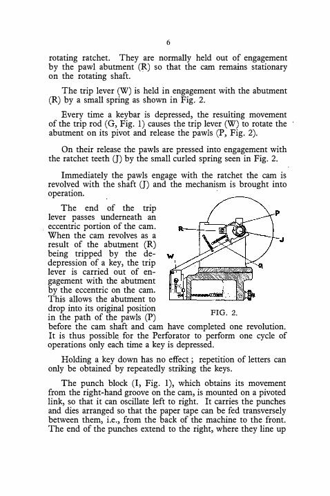
The Perforator is driven by a fractional H.P. motor via a belt drive to a pulley on the cam shaft (J. Fig. 2).
The cam shaft, which is supported by two bearings and revolves continuously, is fitted with a ratchet.
Enveloping the cam shaft, in the form of a sleeve, is the cam which is cut with three grooves shaped and timed to give the necessary movement to the punching, feeding, and comb bar re-setting mechanism.
The cam also carries at its left-hand end, two pivoted pawls (P), the teeth of which, under the action of a spring, are pressed in towards the shaft, where they engage with the teeth of the
6
rotating ratchet. They are normally held out of engagement by the pawl abutment (R) so that the cam remains stationary on the rotating shaft.
The trip lever (W) is held in engagement with the abutment (R) by a small spring as shown in Fig. 2.
Every time a keybar is depressed, the resulting movement of the trip rod (G, Fig. 1) causes the trip lever (W) to rotate the abutment on its pivot and release the pawls (P, Fig. 2).
On their release the pawls are pressed into engagement with the ratchet teeth (J) by the small curled spring seen in Fig. 2.
Immediately the pawls engage with the ratchet the cam is revolved with the shaft (J) and the mechanism is brought into operation.
The end of the trip lever passes underneath an
. eccentric portion of the cam. When the cam revolves as a result of the abutment (R) being tripped by the dedepression of a key, the trip lever is carried out of engagement with the abutment by the eccentric on the cam. This allows the abutment to drop into its original position in the path of the pawls (P)
FIG. 2.
before the cam shaft and cam have completed one revolution. It is thus possibl� for the Perforator to perform one cycle of operations only each time a key is depressed.
Holding a key down has no effect ; repetition of letters can only be obtained by repeatedly striking the keys.
The punch block (I, Fig. 1), which obtains its movement from the right-hand groove on the cam, is mounted on a pivoted link, so that it can oscillate left to right. It carries the punches and dies arranged so that the paper tape can be fed transversely between them, i.e., from the back of the machine to the front. The end of the punches extend to the right, where they line up
7
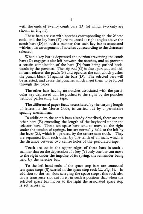
with the ends of twenty comb bars (D) (of which two only are shown in Fig. 1).
These bars are cut with notches corresponding to the Morse code, and the key bars (Y) are mounted at right angles above the comb bars (D) in such a manner that each key bar is associated with•its own arrangement of notches cut according to the character selected.
When a key bar is depressed the portion traversing the comb bars (D) engages a slot left between the notches, and so prevents a certain combination of the bars (D) from being pushed backwards by the purrches. The trip rod (G) is also operated, and this in turn releases the pawls (P) and operates the cam which pushes the punch block (I) against the bars (D). The selected bars will be arrested, and cause the punches which meet them to be forced through the paper.
The other bars having no notches associated with the particular key depressed will be pushed to the right by the punches without perforating the tape.
The differential paper feed, necessitated by the varying length of letters in the Morse Code, is carried out by a permissive spacing mechanism.
In addition to the comb bars already described, there are ten other bars (E) extending the length of the keyboard under the selector bars. These ten space-bars tend to move to the right under the tension of springs, but are normally held to the left by the lever (Z), which is operated by the centre cam track. They are separated from each other by one-tenth of an inch, which is the distance between two centre holes of the perforated tape.
Teeth are cut in the upper edges of these bars in such a manner that on the depression of a key (Y) only one bar can move to the right under the impulse of its spring, the remainder being held by the selector bar.
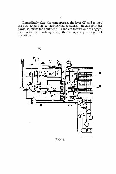
To the left-hand ends of the space-stop bars are connected ten space stops (S) carried in the space stop rack (L, Fig. 3). In addition to the ten slots carrying the space stops, this rack also has a transverse slot cut in it, in such a position that when the selected space bar moves to the right the associated space stop is set across it.
8
The feeding of the paper is carried out by a rake, which is moved backwards and forwards in the transverse groove of the space stop rack. It obtains its movement from the left-hand cam track by way of the spacing lever and spacing lever blade (M). This movement is applied permissively in the backward direction, the amount being determined by the selected space stops. Immediately this movement has taken place the punch block (I) is returned to its normal position by the cam, thus reengaging the paper with the rake, which then moves forward, thus feeding out the tape.
The complete cycle of operations is as follows :-A key bar (Y) is depressed. This enters the slots in the comb bars (D) and space stop bars (E), and, as it nears the end of its stroke, operates the ·trip rod (G), which in turn operates the abutment (R) and allows the pawls (P) to engage with the teeth of the revolving shaft (J). The cam then commences to revolve, and first operates the rod (0), which pushes back the lever (Z) so as to leave space for the comb bars to operate.
As this lever goes back, a space stop bar (E) corresponding to the selected letter will follow it and carry a space stop (S) into the path of the feed rake.
The punch block (I) carrying the punches and the tape is then moved to the right. The punches in this block meet certain bars (D) according to the signal seli;cted, and are forced through the paper tape.
The remaining punches will push the unwanted bars (D) away. The movement of the punch block (I) <;lisengages the feed rake (N) from the paper, and when this has taken place the cam operates the spacing blade (M) and carries the feed rake towards the punch block.
The feed rake travels down its path until it meets the space stop (S) which determines the length of the tape to be fed. As the cam continues to revolve, the punch block is returned to its normal position, and this causes the paper tape to engage once again with the feed rake (N), which in turn is moved by the cam to its normal position, thus feeding the paper tape.
9
Immediately after, the cam operates the lever (Z) and returns the bars (D) and (E) to their normal positions. At this point the pawls (P) strike the abutment (R) and are thrown out of engagement with the revolving shaft, thus completing the cycle of operations.
K
p
F�
FIG. 3.
ci .....
µ.,
11
DISMANTLING AND REASSEMBLING
INSTRUCTIONS.
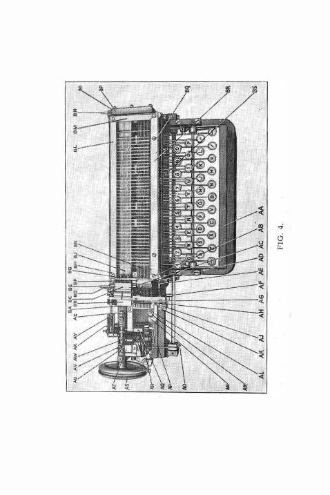
1. To Remove the Operating Unit Complete. (See Fig. 4.)
1.1 Remove the Operating Head Unit Cover, the Belt Guard and the Belt.
1.2 Remove the desk by slackening the two screws (BQ) and extracting the four top screws.
1.3 Depress the space bar (AA) and rotate the cam (AW) slightly, by means of the pulley (AS).
1.4 Remove the pin (BN) and continue to turn the cam until it is arrested by the pawl abutment (AT).
1.5 Push all the Combination Bars (BJ) to the right, flush with the guide plate (BG).
1.6 Remove screw (BH) and whilst holding the Keybar retaining plate (beneath bar BR) remove screw (AB) and the Space Stop Retaining Plate (BF). Replace the screw (AB) immediately and screw it right home before releasing the pressure on the Keybar Retaining Plate.
.
l.7 Remove the Trip Lever Link Spring (AR) from its anchor pin. Remove the Combination Stop Spring (AE).
1.8 Remove the two fixing screws (BA) of the Operating Head Unit.
1.9 Lift the Head vertically, disconnecting the Space Stops (AC) from their associated bars, and the Punch Withdrawing plate and Centre Hole Punch Holder (BD) from their brackets, and remove the Unit from the machine.
2. To Replace the Operating Head Unit as a Complete
Assembly. (See Fig. 4.)
2.1 Move all the combination bars (BJ) to the right flush with the Guide Plate (BG).
2.2 With the Cam (AW) normal, i.e., with the pawls (AU) arrested by the pawl abutment (AT), lower the Unit
12
into position, reinserting the Trip Lever Link (AP) into the pawl abutment and re-engaging the Spa�e Stops (AC) with their ass9ciated bars (BK) and the Punch Withdrawing plate and Centre Punch Holder (BD) with their brackets. Re-engage the Combination Stop with its bellcrank (AD).
2.3 Engage the Unit with its locating key or steady pins and ensure that the unit is seating squarely on the base of the machine. Replace and tighten the fixing screws (BA).
2.4 Engage the Trip Lever Spring (AR) with its anchor and replace the Combination stop spring (AE).
2.5 Replace the Space Stop Retaining Plate (�F).
2.6 Depress any key and rotate the cam (AW) slightly.
2.7 Re-engage the Returning Bar Link (BO) with the Returning Bar (BP) and ins,ert the pin (BN). Adjust the length of the link by screwing it in or out until the spring (AY) is slightly compressed when the cam is arrested by the Pawl Abutment (AT).
2.8 Replace the cover, the desk, the belt and the belt guard.
3. To Remove the Punch Block without Removing the
Operating Head Unit. (See Fig. 4.)
3.1 Remove the Cover and the Desk. (See Section 1.) 3.2 Remove the Cuttings Guide (BB) (1 screw). 3.3 Depress any key and turn the cam (AW) slightly. 3.4 Remove the Returning Bar Lirik Pin (BN). 3.5 Slide all the Combination Bars (BJ) to the right so that
their ends are flush with their L.H. guide plate (BG). 3.6 Continue to turn the Cam until the Punch Block (BC)
is in its extreme R.H. position. 3.7 Depress the Space Stop Bracket Lever (AN) by means
of the adjustment nuts (AM) until it is in its lowest position and the Feed Rake (AH) is clear of the Punch Block.
3.8 Withdraw the two Punch Block Pivot Pins (AX) and (BE).
13
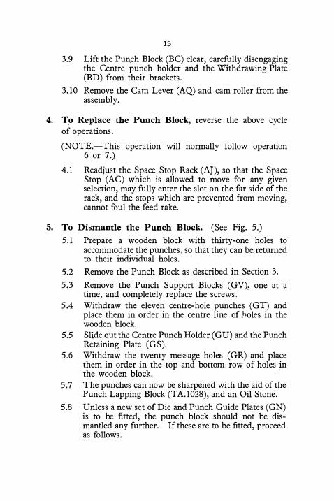
3.9 Lift the Pun.ch Block (BC) clear, carefully disengaging the Centre punch holder and the Withdrawing Plate (BD) from their brackets.
3.10 Remove the Cam Lever (AQ) and cam roller from the assembly.
4. To Replace the Punch Block, reverse the above cycle of operations.
(NOTE.-This operation will normally follow operation 6 or 7.)
4.1 Readjust the Space Stop Rack (AJ), so that the Space Stop (AC) which is allowed to move for any given selection, may fully enter the slot on the far side of the rack, and the stops which are prevented from moving, cannot foul the feed rake.
·
5. To Dismantle the Punch Block. (See Fig. 5.)
5.1 Prepare a wooden block with thirty-one holes to accommodate the punches, so that they can be. returned to their individual holes.
5.2 Remove the Punch Block as described in Section 3.
5.3 Remove the Punch Support Blocks (GV), one at a time, and completely replace the screws.
5.4 Withdraw the eleven centre-hole punches (GT) and place them in order in the centre line of Jioles in the wooden block.
5.5 Slide out the Centre Punch Holder (GU) and the Punch Retaining Plate (GS).
5.6 Withdraw the twenty message holes (GR) and place them in order in the top and bottom row of holes in the wooden block.
·
5. 7 The punches can now be sharpened with the aid of the Punch Lapping Block (TA.1028), and an Oil Stone.
5.8 Unless a new set of Die and Punch Guide Plates (GN) is to be fitted, the punch block should not be dismantled any further. If these are to be fitted, proceed as follows.
14
5.9 Remove the four fixing screws (GW), the front punch guide plate (GN) and the die back plate (GP), after releasing the spring from the anchor pin (GQ).
5.10 Remove the die plate (GN), the distance piece (GO) and the rear punch guide plate (GN).
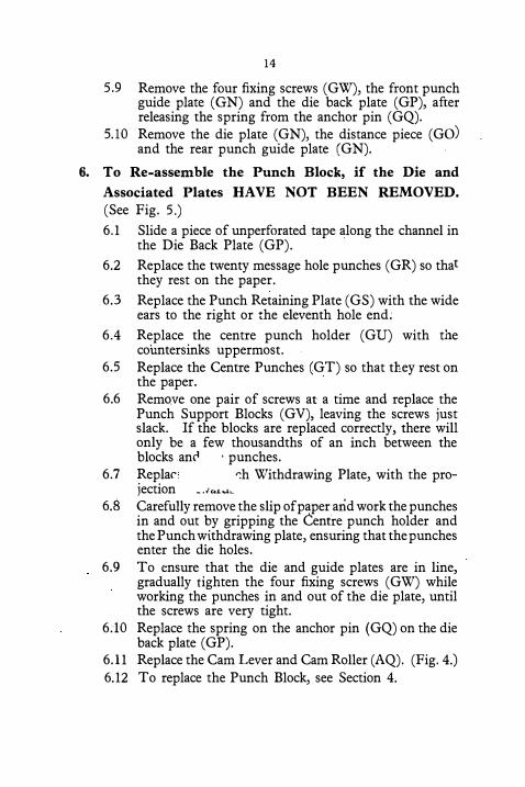
6. To Re-assemble the Punch Block, if the Die and
Associated Plates HAVE NOT BEEN REMOVED.
(See Fig. 5.)
6.1 Slide a piece of unperforated tape along the channel in the Die Back Plate (GP).
6.2 Replace the twenty message hole punches (GR) so that they rest on the paper.
6.3 Replace the Punch Retaining Plate (GS) with the wide ears to the right or the eleventh hole end;
6.4 Replace the centre punch holder (GU) with the countersinks uppermost.
6.5 Replace the Centre Punches (GT) so that they rest on the paper.
6.6 Remo.ve one pair of screws at a time and replace the Punch Support Blocks (GV), leaving the screws just slack. If the blocks are replaced correctly, there will only be a few thousandths of an inch between the blocks .anc1 · punches.
6.7 Repla<' r:h Withdrawing Plate, with the pro-jection _ .«.L...lc
6.8 Carefully remove the slip of paper arid work the punches in and out by gripping the Cenfre punch holder and the Punch withdrawing plate, ensuring that the punches enter the die holes.
6.9 To ensure that the die and guide plates are in line, gradually tighten the four fixing screws (GW) while working the punches in and out of the die plate, until the screws are very tight.
6.10 Replace the spring on the anchor pin (GQ) on the die back plate (GP).
6.11 Replace the Cam Lever and Cam Roller (AQ). (Fig. 4.) 6.12 To replace the Punch Block, see Section 4.
15
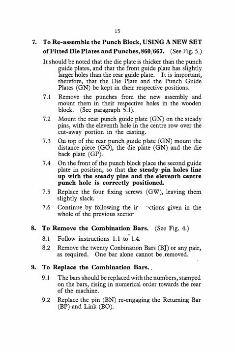
7. To Re-assemble the Punch Block, USING A NEW SET
of Fitted Die Plates and Punches, 860/667. (See Fig. 5.)
It should be noted that the die plate is thicker than the punch guide plates, and that the front guide plate has slightly larger holes than the rear guide plate. It is important, therefore, that the Die Plate and the Punch Guide Plates (GN) be kept in their respective positions.
7.1 Remove the punches from the new assembly and mount them in their respective holes in the wooden block. (See paragraph 5.1).
7.2 Mount the rear punch guide plate (GN) on the steady pins, with the eleventh hole in the centre row over the cut-away portion in the casting.
7.3 On top of the rear punch guide plate (GN) mount the distance piece (GO), the die plate (GN) and the die back plate (GP).
7.4 On the front of the punch block place the second guide plate in position, so that the steady· pin holes line up with the steady pins and the eleventh centre punch hole is correctly positioned.
7.5 Replace the four fixing screws (GW), leaving them slightly slack.
7.6 Continue by following the ir ·1ctions given in the whole of the previous sectior
8. To Remove the Combination Bars. (See Fig. 4.) .
8.1 Follow instructions 1.1 to 1.4.
8.2 Remove the twenty Conbination Bars (BJ) or any pair, as required. One bar alone cannot be. removed.
9. To Replace the Combination Bars.
9.1 The bars should be replaced with the numbers, stamped on the bars, rising in numerical order towards the rear of the machine.
9 .2 Replace the pin (BN) re-engaging the Returning Bar (BP) and Link (BO).
16
10. To Remove the Space Stop Bars. (See Fig. 4.)
10.1 Follow instruction 1.1 to 1.4 and 1.6. 10.2 Remove the Spring Guard (BS).
10.3 Slacken the fixing screws (BA) and raise the Operating Head Unit slightly, sliding a screwdriver beneath it to keep it raised.
10.4 Raise the Space Stops (AC) and disconnect them from the bars (BK).
10.5 Remove the Space Stop Bar Spring Anchor by sliding it to the front of the machine.
10.6 Remove the Space Stop Bars (BK).
11. To Replace the Space Stop Bars.
11.1 Reverse the above cycle of operations, remembering that the bar with the lowest number must be assembled towards the front of the machine.
12. To Remove a Space Stop. (See Fig. 4.)
12.l Remove the belt guard (2 screws) . .
12.2 Depress any key and rotate the cam (AW) slightly.
12.3 Remove the Space Stop Retaining Plate (BF). (See paragraph 1.6).
12.4 Remove the front plate (AK) from the Space Stop Rack (2 screws).
12.5 Slacken the fixing screws (BA) and lift the Operating Head unit sligJ:itly, sliding. a screwdriver beneath it to keep it raised.
12.6 Remove the Space Stop (AC) required.
13. To Replace a Space Stop.
13.l Reverse the above cycle of operati?ns.
14. To Remove the Cam and Pawls. (See Fig. 4.)
14.1 Remove the cover, belt guard and belt. 14.2 Remove the Split Ring and Washer from the
Shaft (AZ).
17
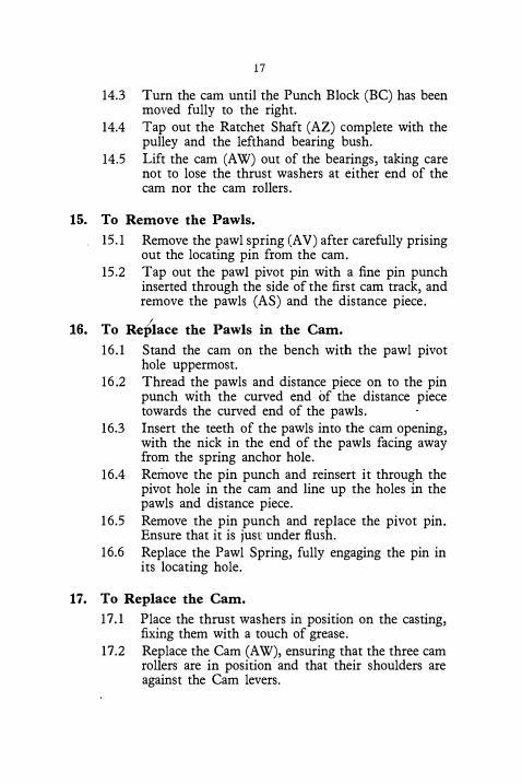
14.3 Turn the cam until the Punch Block (BC) has been moved fully to the right.
14.4 Tap out the Ratchet Shaft (AZ) complete with the pulley and the lefthand bearing bush.
14.5 Lift the cam (AW) out of the bearings, taking care not to lose the thrust washers at either end of the cam nor the cam rollers.
15. To Remove the Pawls.
15 .1 Remove the pawl spring (AV) after carefully prising out the locating pin from the cam.
15.2 Tap out the pawl pivot pin with a fine pin punch inserted through the side of the first cam track, and remove the pawls (AS) and the distance piece.
16. To Replace the Pawls in the Cam.
16.1 Stand the cam on the bench with the pawl pivot hole uppermost.
16.2 Thread the pawls and distance piece on to the pin punch with the curved end of the distance piece towards the curved end of the pawls.
16.3 Insert the teeth of the pawls into the cam opening, with the nick in the end of the pawls facing away from the spring anchor hole.
16.4 Remove the pin punch and reinsert it through the pivot hole in the cam and line up the holes in the pawls and distance piece.
16.5 Remove the pin punch and replace the pivot pin. Ensure that it is just under flush.
16.6 Replace the Pawl Spring, fully engaging the pin in its locating hole.
17. To Replace the Cam.
17 .1 Place the thrust washers in position on the casting, fixing them with a touch of grease.
17.2 Replace the Cam (AW), ensuring that the three cam rollers are in position and that their shoulders are against the Cam levers.
18
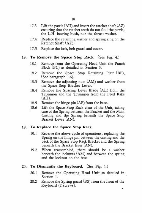
17 .3 Lift the pawls (AU) and insert the ratchet shaft (AZ) ensuring that the ratchet teeth do not foul the pawls, the L.H. bearing bush, nor the thrust washer.
17.4 Replace the retaining washer and spring ring on the Ratchet Shaft (AZ).
17.5 Replace th� belt, belt guard and cover.
18. To Remove the Space Stop Rack. (See Fig. 4.)
18.1 Remove from the Operating Head Unit the Punch Block (BC) as detailed in Section 3.
18.2 Remove the Space Stop Retaining Plate (BF). (See paragraph 1.6).
18.3 Remove the adjusting nuts (AM) and washer from the Space Stop Bracket Lever.
18.4 Remove the Spacing Lever Blade (AL) from the Trunnion and the Trunnion from the Feed Rake (AH).
18.5 Remove the hinge pin (AF) from the base. 18.6 Lift the Space Stop Rack clear of the Unit, taking
care of the Spring between the Bracket and the Main Casting and the Spring beneath the Space Stop Bracket Lever (AN).
19. To Replace the Space Stop Rack.
19.1 Reverse the above cycle of operations, replacing the Spring on the hinge pin between the casting and the back of the Space Stop Rack Bracket and the Spring beneath the Bracket lever (AN).
19.2 When reassembled, there should be a washer beneath the locknuts (AM) and between the spring and the locknut on the base.
20. To Dismantle the Keyboard. (See Fig. 4.)
20.l Remove the Operating Head Unit as detailed in Section 1.
·
20.2 Remove the Spring guard (BS) from the front of the Keyboard (2 screws).
19
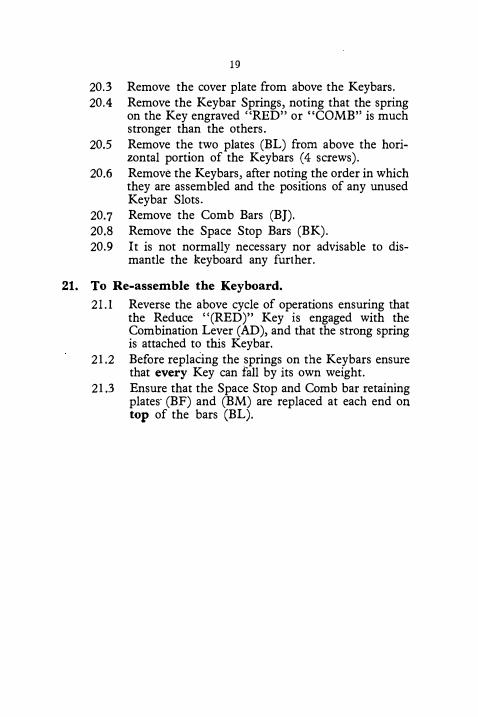
20.3 Remove the cover plate from above the Keybars. 20.4 Remove the Keybar Springs, noting that the spring
on the Key engraved "RED" or "COMB" is much stronger than the others.
20.5 Remove the two plates (BL) from above the horizontal portion of the Keybars (4 screws).
20.6 Remove the Keybars, after noting the order in which they are assembled and the positions of any unused Keybar Slots.
20.7 Remove the Comb Bars (BJ). 20.8 Remove the Space Stop Bars (BK). 20.9 It is not normally necessary nor advisable to dis
mantle the keyboard any further.
21. To Re-assemble the Keyboard.
21.l Reverse the above cycle of operations ensuring that the Reduce "(RED)" Key is engaged with the Combination Lever (AD), and that the strong spring is attached to this Keybar.
21.2 Before replacing the _springs on the Keybars ensure that every Key can fall by its own weight.
21.3 Ensure that the Space Stop and Comb bar retaining plates· (BF) and (BM) are replaced at each end on top of the bars (BL).
20
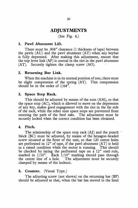
ADJUSTMENTS (See Fig. 4.)
1. Pawl Abutment Lift.
There must be .004" clearance (I thickness of tape) between the pawls (AU) and the pawl abutment (AT) when any keybar is fully depressed. After making this adjustment, ensure that the trip lever link (AP) is central in the slot in the pawl abutment (AT). Securely tighten the clamp screw (AO).
2. Returning Bar Link.
When the machine is in its normal position of rest, there must be slight compression of the spring (A Y). This compression should be in the order of 1/64".
3. Space Stop Rack.
This should be adjusted by means of the nuts (AM), so that the space stop (AC), which is allowed to move on the depression of any key, makes good engagement with the slot in the far side of the rack, while the other nine space stops are prevented from entering the path of the feed rake. The adjustment must be securely locked when the correct condition has been obtained.
4. Pitch.
The relationship of the space stop rack (AJ) and the punch block (BC) must be adjusted, by means of the hexagon-headed screw situated at the front of the unit, so that 120 centre holes are perforated in 12" of tape, if the pawl abutment (AT) is held in a raised condition while the motor is running. This should be checked by laying the perforated tape on a 12" steel rule, marked in 1/10". Each 1/10" marking should pass through the centre line of a hole. The adjustment must be securely clamped by means of the locknut.
5. Counter. (Visual Type.)
The adjusting screw (not shown) on the returning bar (BP) should be adjusted so that, when the bar has moved to the limit
21
of its travel, the feed pawl of the letter counter shall have engaged the next tooth on the ratchet wheel. The adjusting screw must be securely clamped by its locknut.
6. Counter. (Non-Visual Type).
The relationship of the Feed Pawl and Retaining Pawl should be such that with the machine at rest there are four clear teeth between the two pawls.
7. Touch.
The knurlea nut (not shown) at the extreme left-hand rear corner of the machine should be adjusted to its mean position, A force of 2i-3 ozs. should be needed to depress fully any key. except the "RED" key, when the motor is running.
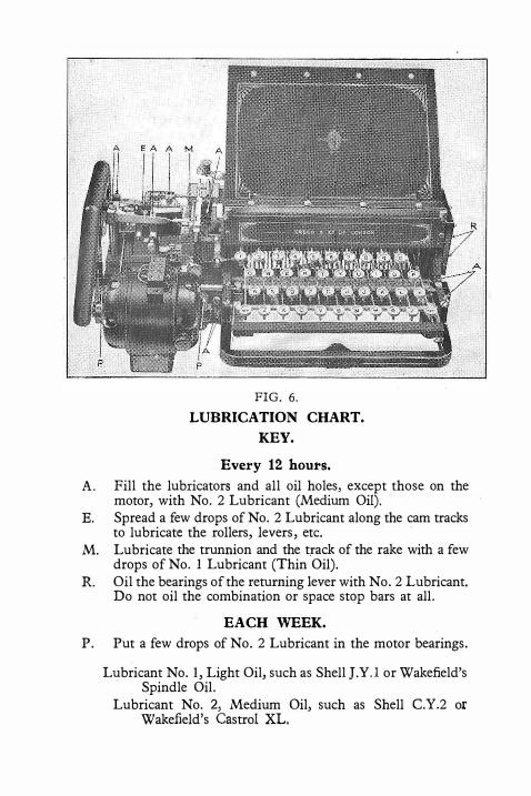
FIG. 6.
LUBRICATION CHART.
KEY.
Every 12 hours.
A. Fill the lubricators and all oil holes, except those on the motor, with No. 2 Lubricant (Medium Oil).
E. Spread a few drops of No. 2 Lubricant along the cam tracks to lubricate the rollers, levers, etc.
M. Lubricate the trunnion and the track of the rake with a few drops of No. 1 Lubricant (Thin Oil).
R. Oil the bearings of the returning lever with No. 2 Lubricant. Do not oil the combination or space stop bars at all.
EACH WEEK.
P. Put a few drops of No. 2 Lubricant in the motor bearings.
Lubricant No. I, Light Oil, such as Shell J.Y.l or Wakefield's Spindle Oil.
Lubricant No. 2, Medium Oil, such as Shell C.Y.2 or Wakefield's Castrol XL.
23
POSSIBLE FAULTS AND
RECTIFICATION
Jumping or Double Punching.
This may be caused by the pawl abutment or the pawls being worn, allowing the pawls to slip off the abutment, and causing the cam to· make two revolutions instead of one per depression of a key. This is first apparent when the space bar gives extra spaces, the reason being that when spacing, the speed is increased owing to there being less load on the motor. If the trip lever is not central in the abutment the fault may occur.
Elongated Centre Holes.
This may be caused by any of the following causes :-
(a) Feed rake sluggish due to cuttings, or fluff, in the track in the space stop rack ; the use of any but Lubricant No. 1 on the trunnion block guide pin.
, (b) Tape may be pulling, bringing up with a jerk after a
free run of the tape wheel.
( c) Punches may not be sharp and the shutters thrown up may bend over in the track between the die and the punch block distance piece, giving the spacing lever blade extra work to do.
(d) Feed rake may not be central in the slot of the paper guide glass or in the slot of the die back plate, or there may be fluff in the tape guide.
(e) Spring washer at the rear of the space stop bracket may have lost its tension and allowed the bracket to move.
(f) The spacing lever spring may have become too weak.
(g) Incorrect setting of the space stop rack by means of the hexagon headed screw.
Extra Holes Perforated. There may be friction between the combination bars. These
bars should be wiped dry and clean and should never be lubricated. If two keys are depressed at the same time extra holes will be perforated.
24
High Pitched Buzz or Hum.
This may be caused by a broken pawl or by an incipient siezure due to lack of oil, causing extra strain on the cam, which pulls up the motor and prevents the pawls from being thrown out of engagement. Incorrect setting of the comb returning bar adjustment will also cause this fault.
Insufficient Holes Being Punched.
The adjustment of the trip lever may be incorrect, causing the pawl abutment to trip before the key bar is in engagement with the projections on the comb bars. Projections on the comb bars may be worn or the punches may be short.
Keybars Sluggish.
This may be due to the Keybars fouling the projections on ·either the space stop bars or the combination bars. It should be corrected-after ensuring that the returning bar link is correctly adjusted (see adjustment 2)-by adding packing shims beneath the respective buffer plates on the returning bar, until there is a .010" clearance between the Keybars and the projections on the bars when the machine is normal.
Lubrication.
See lubrication chart, Fig. 6.
25
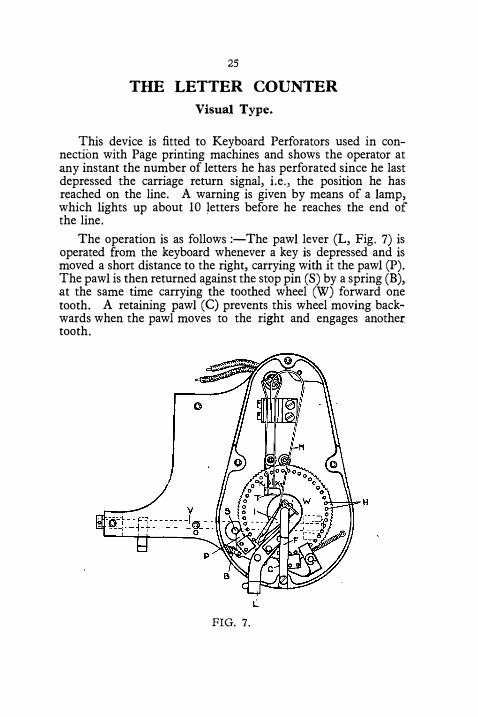
THE LETTER COUNTER
Visual Type.
This device is fitted to Keyboard Perforators used in connection with Page printing machines and shows the operator at any instant the number of letters he has perforated since he last depressed the carriage return signal, i.e., the position he has reached on the line. A warning is given by means of a lamp, which lights up about IO letters before he reaches the end of the line.
The operation is as follows :-The pawl lever (L, Fig. 7) is operated from the keyboard whenever a key is depressed and is moved a short distance to the right, carrying with it the pawl (P). The pawl is then returned against the stop pin (S) by a spring (B), at the same time carrying the toothed wheel (W) forward one tooth. A retaining pawl (C) prevents this wheel moving backwards when the pawl moves to the right and engages another tooth.
L
FIG. 7.
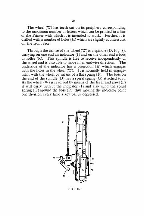
26
The wheel (W) has teeth cut on its periphery corresponding to the maximum number of letters which can be printed in a line of the Printer with which it is intended to work. Further, it is drilled with a number of holes (H) which are slightly countersunk on the front face.
Through the centre of the wheel (W) is a spindle (D, Fig. 8), carrying on one end an indicator (I) and on the other end a boss or roller (R). This spindle is free to receive independently of the wheel and is also able to move in an endwise direction. The underside of the indicator has a projection (E) which engages with the holes in the wheel (W). It is normally held in engagement with the wheel by means of a flat spring (F). The boss on the end of the spindle (D) has a spiral spring (G) attached to it. As the wheel (W) is revolved by means of the lever and pawl (P) it will carry with it the indicator (I) and also wind the spiral spring (G) around the boss (R), thus moving the indicator point one division every time a key bar is depressed.
M
FIG. 8.
27
Behind the indicator is a trip shaft (V) which is operated whenever the ·carriage return key is depressed. A lever (M) on this shaft bears against the end of the spindle (D) and when the carriage return key is depressed, pushes the spindle and indicator out of engagement with the wheel (W). The spiral spring (G), which has been coiled round the boss (R), immediately returns the indicator to zero. When the spindle (D) is released, the projection (E) will re-engage with a· hole in the wheel (W).
Provision is made for preventing the wheel (W) carrying the indicator round further than the end of line position, i.e., preventing the spiral spring (G) being over-wound by neglecting to operate the carriage return key. This is effected by the lower portion of the indicator (I) which, as the end of line position is reached, comes into contact with a projection on the retaining pawl (C), forcing it out of action and so preventing the pawl (P) from feeding the wheel forward.
The contacts for closing the warning lamp circuit are at K. l and K.2. K.2 is fixed, but K. I is on a spring blade which would normally rest against K.2. It is, however, held away by a
spring (N) bearing against the insulated block (T). As the indicator is revolved and nears the end of its scale, a projection on it engages the spring (N) and carries the latter with it, so allowing the contact K. l to bear against K.2. Immediately the indicator is released and returned to zero, spring (N) will cause the contacts to open again.
Adjustment of Counter.
The stud operating the pawl lever (L) should be so adjusted that at its full stroke the pawl (P) will feed one and a half teeth, or as near to this as possible. The indicator (I) should be released at approximately the same instant that the pawls are released, when the carriage return key is depressed. Adjustment for this is provided by means of a screw in the lever (A) at the back of the counter. After slackening the clamping nut the screw can be adjusted so that the Indicator is released at the correct instant.
28
TOOLS AND ACCESSORIES.
Tool Kit No. 9.
1 Spring hook 2 Spanners 4BA and 6BA
1 Punch lapping block C.P.
Punch block cleaner (double edge) Punch block cleaner (single edge) pair pliers for removing locking rings
1 Screwdriver, 5" x �"
1 Screwdriver, 5" x f'
2 Oil cans (watch pattern) 1 pair tweezers ...
Accessories List No. 9.
5 coils tape, plain parchment (standard .475" wide) or 5 coils tape, plain parchment (f' wide)
1 -! pint can Lubricant No. 1 (thin oil) 1 ± pint can Lubricant No. 2 (medium oil)
1 Instruction Booklet No. 16. 1 Part List No. 1016. 1 Keyboard Chart.
TA.1008 TA.1022 TA.1028 TA.1034
TA. 1035 TA.1023
8549
8550 8620 8199
ABARL ABACK
9350
9349

N <:J
"' \?
--
0 ('.)

Printed in Gt. Britain by
THE VICTORY PRESS
LeicMl4lr t\Dd �ndon.


![Android Interactive Learning Morse App [Learn Morse] Morse Detailed Insrtuctions.pdfAndroid Interactive Learning Morse App [Learn Morse] Version v1.0 - April 2015 Introduction: Caution!](https://img.dokumen.tips/doc/110x75/5f2e43e86c3c8526ba625367/android-interactive-learning-morse-app-learn-morse-morse-detailed-android-interactive.jpg)