Embed Size (px)
Citation preview

The Microprocessor-based PC System
Prima Dewi PurnamasariMicroprocessor
Electrical Engineering DepartmentUniversity of Indonesia

What is Computer?
• Basically, there are 3 components to build a computer, and those three are interconnected with wires. Could you name it?
Microprocessor (c) Prima Dewi Purnamasari 2011 2
? ??
General Block Diagram of the PC
Fig. 1.2 shows the general block diagram of the PC
3Microprocessor (c) Prima Dewi Purnamasari 2011

Microprocessor (c) Prima Dewi Purnamasari 2011 4
MemoryMicroprocesso
rI/O
BUS

MICROPROCESSOR
Microprocessor (c) Prima Dewi Purnamasari 2011 5
The Microprocessor
• The microprocessor is the controlling element in a computer system and is sometimes referred to as the CPU (Central Processing Unit)
• Memory and I/O are controlled through instructions that are stored in the memory and executed by the microprocessor
6Microprocessor (c) Prima Dewi Purnamasari 2011
• The microprocessor performs three main tasks for the computer system:
1. Data transfer between itself and the memory or I/O systems
2. simple arithmetic & logic operations (Table 1.3)
3. program flow via simple decisions (Table 1.4)
Microprocessor (c) Prima Dewi Purnamasari 2011 7
The Microprocessor

Microprocessor (c) Prima Dewi Purnamasari 2011 8

Microprocessor (c) Prima Dewi Purnamasari 2011 9

The Microprocessor
• Why the microprocessor is powerful?– Able to execute millions of instructions per
second from a program or software (group of instructions) stored in the memory system
– able to make simple decision, based upon numerical facts (Table 1.4)
10Microprocessor (c) Prima Dewi Purnamasari 2011

MEMORY
Microprocessor (c) Prima Dewi Purnamasari 2011 11

Memory
• The memory system is divided into three main parts: – TPA (Transient Program Area)– system area, – XMS (Extended Memory System) (optional)
12Microprocessor (c) Prima Dewi Purnamasari 2011

Memory System
• The first 1M byte of memory the real/conventional memory system. Intel mP is designed to function this area in real mode of operation
• 80286 Pentium 4 contain not only real memory, but also extended memory
• The Pentium Pro-based computer system, for example, can have up to 1M less than 4G or 1M less than 64G of extended memory
13Microprocessor (c) Prima Dewi Purnamasari 2011

Memory Address
• In Hexadecimal format• 1MByte Real Memory:
= 220 x 1 Byte= 1 0000 0000 0000 0000 0000 B x 1 Byte
• Each block of memory holds 1 Byte (8 bits) data
• 1MByte memory address:– Starting address (#1) : 00000H– Ending address (#220): FFFFFH
Microprocessor (c) Prima Dewi Purnamasari 2011 14
Trivia
• How if 2MByte Memory? What is the starting and ending address?
Microprocessor (c) Prima Dewi Purnamasari 2011 15

Trivia
• How if 2MByte Memory? What is the starting and ending address?
• 2MB = 221 = 1 1111 1111 1111 1111 1111 (21 x 1)= 1FFFFF H
Starting address = 000000HEnding address = 1FFFFFH
Microprocessor (c) Prima Dewi Purnamasari 2011 16

Memory Illustration
FFFFFH …
………… …
………… …
………… …
00002H …
00001H 0111 0001 B
00000H 0AH
Microprocessor (c) Prima Dewi Purnamasari 2011 17
Memory Address
Each block of memory contains 1 Byte or 8 bits dataEach block of memory contains 1 Byte or 8 bits data

Microprocessor (c) Prima Dewi Purnamasari 2011 18
Memory System

Transient Program Area (TPA)
• Holds the OS and other program that control the computer system
• Stores any currently active or inactive application programs
• The length of TPA is 640 KB
Microprocessor (c) Prima Dewi Purnamasari 2011 19

Memory map of TPAThe memory map (fig. 1.4, in hexadecimal addr.) shows how many areas of the TPA are used for system programs, data, and drivers
Microprocessor (c) Prima Dewi Purnamasari 201120

TPA
• The interrupt vectors access various features of the DOS, BIOS (Basic I/O System), and application
• The BIOS and DOS communications areas contain transient data used by program to access I/O devices and internal features of the computer system
21Microprocessor (c) Prima Dewi Purnamasari 2011

TPA
• The IO.SYS is a program that loads into the TPA from the disk whenever an MSDOS or PC DOS system is started
• The MSDOS (PCDOS) program occupies two areas of memory
• The size of the driver area and # of drivers change from one computer to another
Microprocessor (c) Prima Dewi Purnamasari 2011 22

TPA
• The COMMAND.COM program controls the operation of the computer from the keyboard when operated in DOS mode
• The free TPA area holds application programs as they are executed
Microprocessor (c) Prima Dewi Purnamasari 2011 23
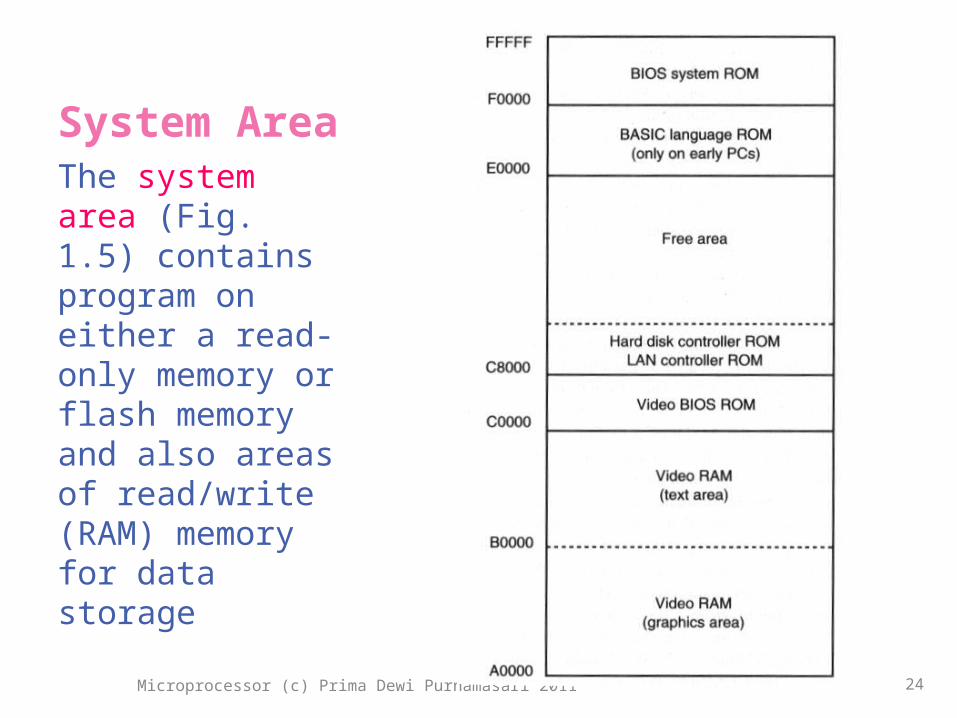
System AreaThe system area (Fig. 1.5) contains program on either a read-only memory or flash memory and also areas of read/write (RAM) memory for data storage
Microprocessor (c) Prima Dewi Purnamasari 2011 24
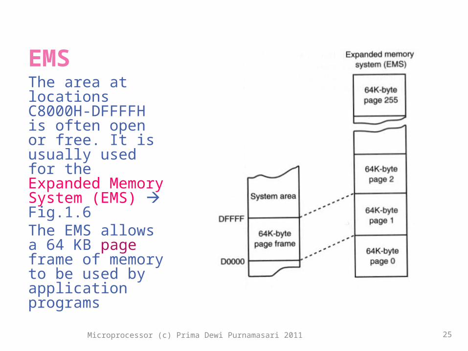
EMSThe area at locations C8000H-DFFFFH is often open or free. It is usually used for the Expanded Memory System (EMS) Fig.1.6The EMS allows a 64 KB page frame of memory to be used by application programs
Microprocessor (c) Prima Dewi Purnamasari 2011 25
I/O
Microprocessor (c) Prima Dewi Purnamasari 2011 26
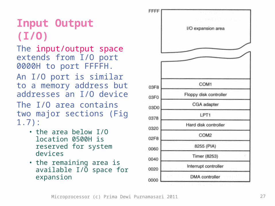
Input Output (I/O)The input/output space extends from I/O port 0000H to port FFFFH. An I/O port is similar to a memory address but addresses an I/O deviceThe I/O area contains two major sections (Fig 1.7):
• the area below I/O location 0500H is reserved for system devices
• the remaining area is available I/O space for expansion
Microprocessor (c) Prima Dewi Purnamasari 2011 27

BUS
Microprocessor (c) Prima Dewi Purnamasari 2011 28

Buses
• A bus is a set of common connections (wires ) that interconnect components in a computer system and carry the same type of information
• Function:1. select an I/O or memory device2. transfer data between an I/O device or
memory and the microprocessor3. control the I/O and memory system
29Microprocessor (c) Prima Dewi Purnamasari 2011

BUSSESThree buses exist for the transfer of information: 1)address, 2)data,3)control
Microprocessor (c) Prima Dewi Purnamasari 2011 30

Buses (cont’d)
• The control bus contains lines that select the memory or I/O and cause them to perform a read or write operation.
• Four control bus connections: MRDC, MWTC, IORC, IOWC
• The address bus requests a memory location from the memory or an I/O location from the I/O devices
31Microprocessor (c) Prima Dewi Purnamasari 2011

Buses (cont’d)
• Example the micro-instructions for READ:
1. the p reads the contain of memory location by sending the memory an address through address bus
2. the p sends the memory read control signal (MRDC) to cause memory to read data via control bus
3. the data read from the memory are passed to the microprocessor through the data bus
32Microprocessor (c) Prima Dewi Purnamasari 2011

Buses (cont’d)
• The (maximum) memory sizes and organizations differ between various member of the Intel p family
• Data bus size defines the amount of data can be transferred at a time (8, 16, 32, 64 bit)
• Address bus size corresponds to (maximum) memory size can be attached to the microprocessor
• Table 1.5 depicts a complete listing of bus and memory sizes on the Intel family of p
33Microprocessor (c) Prima Dewi Purnamasari 2011

Microprocessor (c) Prima Dewi Purnamasari 2011 34

NUMBER SYSTEMSSelf reading…
Microprocessor (c) Prima Dewi Purnamasari 2011 35