Embed Size (px)
Citation preview

The Margaret Stanier Memorial Sundial
Unequal-Hours with a Difference
The New Sundial at Newnham College, Cambridge
A Gnomonic Explanation
by
Frank H. King
Cambridge September 2010

Margaret Stanier, Scientist
Margaret Stanier was a Fellow, College Lecturer in Physiology, and Director of Studies inMedicine and Veterinary Science at Newnham College, Cambridge, from 1962 to 1984. Shewas elected a Fellow Emerita in 1984 and continued to be much involved with the Collegeuntil her death in 2007.
Margaret Stanier was Editor of the British Sundial Society Bulletin and she was also a well-known bellringer in the Cambridge area. The writer of this explanation is the UniversityBellringer in Cambridge and knew Margaret Stanier well. He regards it as a great honourto have played a part in creating this sundial as a memorial to her.
The Sundial
To those unfamiliar with sundials some explanation is necessary because this dial does notindicate ordinary clock time, even approximately. This dial indicates the fraction of thedaylight period that has elapsed since sunrise.
On this sundial, the unit of time used is one-twelfth of the period from sunrise to sunset.Such units are termed hours, but they are clearly longer in summer than in winter so theyare known as unequal-hours. In the cover photograph, the time-indicating shadow fallshalf-way between VII and VIII so seven and a half unequal-hours have been completedsince sunrise.
To those who are familiar with sundials, even more explanation is necessary because thehour-lines on a proper unequal-hours dial are not straight. Accordingly, a straight rodgnomon cannot be used to cast the shadow and there is a seemingly intractable problem:
How can this sundial work if it breaks the usual gnomonic rules?
The explanation is presented as a sequence of diagrams which form the first half of thisdocument. The second half describes the evolution of the design and the construction ofthe sundial. No prior knowledge of sundials is required!
Outline Explanation for Experts
The gnomon lies in the meridian plane and is offset from the horizontal by a small well-chosen angle. Each hour-line is drawn at the best-fit angle for the unequal-hour indicated.For further understanding of the terms ‘well-chosen’ and ‘best-fit’, read on.
Health Warning
The noted Italian gnomonista, Gianni Ferrari, commenting on the hour-lines, has statedthat they ‘don’t have great gnomonic meaning’ ! Study the pages which follow and judgefor yourself!

1 — Time by the Sun
6
7
8
9
1011 12 13
14
15
16
17
18
EAST
SOUTH
WEST
Fig. 1 — A wide-angle View of the Equinoctial Sun
Fig. 1 shows the position of the sun in the sky at hourly intervals from sunrise to sunseton the day of an equinox. An ultra-wide angle of view is portrayed; this view extends fromdue east via due south to due west and so includes both the rising and setting sun.
At an equinox, the sun rises at 6 am and sets at 6 pm. These times may be written as 6hand 18h using the 24-hour clock. At midday, noon, the time is 12h and the sun is at itshighest point and due south (in northern latitudes).
The figure shows an ideal horizon as might be imagined in Cambridge Fenland. The horizonseparates the clear blue sky from verdant grassland. Due south is marked by a small blacktriangle, the top of a church spire perhaps. The vertical line which runs upwards from thismarker through the position of the sun at 12h is the local meridian.
Together, the observer and the meridian define a plane which is vertical and lies duenorth–south. This is the observer’s meridian plane.
An arc has been drawn through the sequence of sun images to show the path taken by thesun across the sky during an equinoctial day.
Two other arcs are drawn as broken lines. The lower shows the path taken by the sun atthe winter solstice when it rises much later and sets much earlier. Moreover, it rises wellto the south of due east and sets well to the south of due west.
The top arc shows the path taken by the sun at the summer solstice when it rises muchearlier and sets much later. Moreover, it rises well to the north of due east and sets wellto the north of due west.
The diagram is appropriate for the latitude of Cambridge. Nearer the tropics, the arcswould be much higher at noon and, nearer the arctic, the arcs would be much lower atnoon. In the arctic itself, the winter solstice arc would be wholly below the horizon. Theland of the midnight sun is, in winter, the land of midday darkness.
– 1 –

2 — Equal-Hour Hour-Lines
6
7
8
9
1011 1 2 13
14
15
16
17
18
EAST
SOUTH
WEST
Fig. 2 — Equal-Hour Hour-Lines and Constant-Declination Arcs
Fig. 2 is an augmentation of Fig. 1 and shows one way of pin-pointing the position of the sunin the sky at any time of day at any time of year. The three arcs and the radial straightlines suggest a system of coordinates which correspond to the terrestrial coordinates oflatitude and longitude.
The celestial equivalent of latitude is declination. The middle arc is the celestial equator.At an equinox, the sun is on the celestial equator and its declination is 0◦. There is thensome point on the terrestrial equator where the sun is directly overhead.
At the summer solstice, the sun is on the upper arc and its declination is about 231
2
◦
. Itis directly over some point on the Tropic of Cancer.
At the winter solstice, the sun is on the lower arc and its declination is about −23 1
2
◦
. Itis directly over some point on the Tropic of Capricorn.
The sun never ventures outside the bounds of the two tropics.
The celestial equivalent of longitude is hour-angle. Often hour-angles are expressed inhours as 6h, 12h and 18h. The straight lines in the figure are known as hour-lines andcorrespond to lines of longitude. Each is labelled with its associated hour-angle (thoughthe h’s have been omitted).
These are equal-hour hour-lines because the time taken for the sun to move from onehour-line to the next is always one ordinary 60-minute hour whatever the time of year.
Extended downwards, the hour-lines meet at a point which is due south but a very longway below the horizon. This point is the south celestial pole.
Just four images of the sun are shown. The equinoctial sun is shown at sunrise and sunset;the declination is 0◦ and the two hour-angles are 6h and 18h. The sun is also shown atsunrise and sunset at the winter solstice; the declination is −23 1
2
◦
and the two hour-anglesare about 81
4h and 153
4h (or 08:15 and 15:45 when expressed as ordinary times).
– 2 –

3 — Unequal-Hour Hour-Lines
I
II
III
IIIIV V I VII
VIII
IX
X
XI
EAST
SOUTH
WEST
Fig. 3 — Unequal-Hour Hour-Lines and Constant-Declination Arcs
Fig. 3 shows an alternative way of pin-pointing the position of the sun in the sky. Thethree arcs are exactly as before, but the hour-lines are quite different.
In this scheme, each arc is divided into 12 equal segments starting at sunrise and endingat sunset. The segments are still called hours but these hours are shorter than 60 minutesin winter and longer than 60 minutes in summer. For this reason they are called unequal-hours. At an equinox, an unequal-hour is the same length as an ordinary 60-minute hour.
In the figure, the labels I to XI on the unequal-hour hour-lines indicate the number ofunequal-hours since sunrise. Two special-case hour-lines are unlabelled. These run alongthe eastern and western horizon and correspond to zero (sunrise) and twelve (sunset).
Two positions of the rising sun are shown, one at an equinox and the other at the wintersolstice. The rising sun at the summer solstice is off the figure on the left. The setting sunis likewise shown only at an equinox and at the winter solstice.
Unequal-hours were once the normal way of reckoning time in Europe. Expressions suchas ‘from the sixth hour to the ninth hour’ refer to unequal-hours.
Notice the numbering. The unequal-hour hour-line for the middle of the day is labelled VIand represents the ‘end of the sixth hour’. At an equinox, unequal-hours can be convertedto ordinary hours just by adding six.
The curvature of the unequal-hour hour-lines in the figure is largely a consequence of theprojection used to represent part of the surface of a sphere on a flat diagram. On thecelestial sphere itself, equal-hour hour-lines are arcs of great circles (they are like lines oflongitude) but unequal-hour hour-lines are not arcs of great circles though for much oftheir length they are quite close approximations to great circles.
When extended beyond the winter-solstice arc, the unequal-hour hour-lines meet at a point.They curve towards the church spire, the south marker on the horizon.
– 3 –

4 — A Primitive Sundial
Fig. 4 — A Stub Gnomon in a South-Facing Disc
It is time to look at a very simple sundial design which was widely used in medieval times.The underlying theory, though flawed, is worth presenting partly because so many dialswere made to this design and partly because the theory is delightfully simple!
A common arrangement was to draw a circle on a vertical south-facing wall and drive aspike into the centre. The spike would be perpendicular to the plane of the circle.
Fig. 4 shows such an embryonic sundial as an isolated disc; imagine this as having beencut out of the wall. The spike or gnomon is horizontal and a north pointer (the arrowstraddled by an N) has been drawn to emphasise that the gnomon points due south. Thedisc, which will eventually be marked out as the dial, also faces due south.
The gnomon is shown casting a shadow. It is clear from the direction of the shadow thatthe sun is in the eastern half of the sky and that it is some while after sunrise but it ispremature to suggest what time is indicated.
The gnomon has two ends, the root and the tip. The shadow of the gnomon also has twoends; one end necessarily coincides with the root of the gnomon but the position of theother end, the shadow of the tip of the gnomon, varies with the time of day and with thetime of year.
The shadow of the gnomon as a whole indicates a direction on the dial, an angle relativeto some reference direction, and the shadow of the tip of the gnomon indicates a point onthe dial.
– 4 –

5 — The first Three Hour-Lines
Fig. 5 — Three Cardinal Hour-Lines
Fig. 5 shows an augmented version of the embryonic sundial of Fig. 4. The gnomon ismuch longer and now extends through the thickness of the dial to the north side.
The position of the sun at sunrise is shown schematically at three different times of year:at the summer solstice when it is north of due east, at an equinox when it is due east, andat the winter solstice when it is south of due east.
It will be assumed by definition that at sunrise and sunset the sun is on the horizon andin the same horizontal plane as the gnomon.
With the sun and gnomon in the same horizontal plane, the shadow will also be horizontal.At sunrise the shadow is horizontal to the west. In the summer, when the sun rises northof due east, this shadow falls on the north side of the dial. In winter, when the sun risessouth of due east, this shadow falls on the south side.
At sunset the shadow will again be horizontal but to the east and, as with sunrise, theshadow may be on the north or south side of the dial.
At midday, whatever the time of year, the sun is in the meridian plane of the centre of thedial. With the gnomon and the sun in the same vertical north-south plane, the shadowwill be vertical and run downwards along the vertical centre-line of the dial.
The three lines marked on the dial are hour-lines indicating sunrise (to the left), midday(downwards) and sunset (to the right). It is assumed that these markings run through thethickness of the dial so that they serve their purpose even when the shadow falls on thenorth (hidden) side.
In the tropics, the midday shadow may fall on the north or south side of the dial dependingon the time of year. At sufficiently southern latitudes the sun is always due north at middayso the shadow will fall on the north side.
– 5 –

6 — Erroneous Unequal-Hours Dial
SUNRISE SUNSET
III
III
IIIIV
VI VIIVIII
IX
X
XI
Fig. 6 — Complete Outline Erroneous Unequal-Hours Dial
Note that the design shown in Fig. 5 is universal. The three hour-lines could be labelledsunrise, midday and sunset and would correctly indicate these times of day wherever thedial was set up on the Earth’s surface provided only that the sun rises and sets. This isnot the case in the land of the midnight sun.
It is of minor, mathematical, interest that a fourth hour-line could be drawn verticallyupwards from the centre. This is for midnight when the sun is at its lowest point which isusually below the horizon. For the shadow of the gnomon to fall on the midnight hour-linethe Earth would have to be transparent. If, at midnight, the sun is above the horizon, theshadow will fall along the midday hour-line and the design fails.
The theory, so far, is sound. Moreover, the dial may face in almost any direction. Theprincipal constraint is that the gnomon must lie along the intersection of the meridianplane and the horizontal plane. The gnomon must therefore be aligned north–south andbe horizontal. A secondary constraint is that the dial must not itself be horizontal or facedue east or west.
The design process gets into difficulties when the daylight period is further subdivided.The ancients simply marked out hour-lines at 15◦ intervals as in Fig. 6. This figure showsthe south side of the dial in elevation looking directly at the tip of the gnomon (whichappears simply as a dot).
The sunrise and sunset hour-lines have been labelled as such and the other hour-lines havebeen labelled I to XI. Unfortunately equal angular intervals do not correspond to equalintervals of time (unless the dial is set up on the equator). Accordingly, the hour-linesdivide the day somewhat erratically in time. Of the hour-lines labelled I to XI, only VI iscorrect.
– 6 –

7 — Erroneous Unequal-Hours Dial
Fig. 7 — The Mass Dial at Little S. Mary’s Church, Cambridge
Notwithstanding the limitations of the 15◦-interval hour-lines, many sundials survive fromthe time that this design was in common use. The photograph in Fig. 7 shows a sundialon Little S. Mary’s Church in Cambridge which approximately conforms to the descriptiongiven above. This sundial probably dates from the late 14th century.
To suggest that whoever marked out this dial had a design like Fig. 6 in mind would betaking liberties with historical accuracy. Nevertheless the dial is circular and faces roughlysouth and the hour-lines are marked at intervals of around 15◦ intervals. The gnomon hasbroken off but its root is clear as a rusty stump in the centre of the dial.
Such a dial is known as a Mass Dial. The Priest would use the dial to determine when toring a bell to call people to prayer. This was the principal purpose of such dials. Giventheir generally rather crude appearance, these dials are often colloquially referred to asscratch dials. Margaret Stanier took a particular interest in such dials.
– 7 –

8 — Erroneous Unequal-Hours Dial
SUNRISE SUNSET
III
III
IIII
V
VIVII
VIII
IXX
XI
Fig. 8 — Error Pattern for the Erroneous Unequal-Hours Dial
Fig. 8 is a first attempt at error analysis and gives an indication of just how badly the15◦-interval design fails.
The dial is as in Fig. 4, a single-sided dial facing due south. Each grey area shows, forthe unequal-hour given by its label, the range of directions in which the shadow of thegnomon may fall when the dial is set up in the latitude of the dial at Newnham College,Cambridge. This is 52◦ 11′ 58′′ N.
One imagines observing the direction of the shadow at each unequal-hour every day for ayear with the proviso that no observation is made when the sun shines on the north side.In the cases of unequal-hours I, II, X and XI (and also sunrise and sunset), there are manydays in the summer months when the sun, at these times, shines on the north side.
The two straight-edge margins of each grey area show the extreme directions in whichthe shadow may fall at the unequal-hour shown by the label. No two adjacent grey areasoverlap but some of the gaps are uncomfortably narrow.
At sunrise, midday, and sunset, the direction of the shadow is independent of the time oryear. For the other unequal-hours, the direction shows great variability.
The hour-lines of Fig. 6 are reduced to short tick marks drawn at 15◦ intervals. Apartfrom those at sunrise, midday and sunset, none of these tick marks falls in the correct greyarea. For example the first tick mark after sunrise is in grey area II so at unequal-hour IIthe shadow can (on occasions) fall on hour-line I.
A simple improvement would be to abandon the 15◦ intervals and move the tick marks orhour-lines to the mid-range positions (the centres of the grey areas) though that turns outto be a slightly naıve approach.
A more ambitious goal is to reduce the ranges indicated by the grey areas.
– 8 –

9 — Using a Nodus
Fig. 9 — A Gnomon capped by a Disc Nodus
It was remarked, when discussing Fig. 4, that the tip of a gnomon indicates a point on adial and, for emphasis, it is common to ornament the tip with a ball or disc or some otherdistinguishing feature. This is called a nodus and an example is shown in the photographin Fig. 9 where the nodus is in the form of a disc which is mounted on the end of thegnomon which is itself perpendicular to the plane on which it is mounted.
A circular disc which is parallel to the plane onto which it casts a shadow will cast acircular shadow. The overall appearance of the shadow in Fig. 9 is that of a drumstick.
The Newnham College Dial does not have a nodus but consideration of the shadow of animaginary nodus was an important part of the design process. It is particularly instructiveto trace the path followed by the centre of the shadow of a nodus during the course of aday. . .
– 9 –

10 — Using a Nodus
9 12 15
Fig. 10 — The Shadow at Equal-Hour Intervals at an Equinox
Fig. 10 again shows the circular dial in elevation but it is now equipped with a gnomonand nodus as in Fig. 11. The open circle in the centre of the figure represents the discnodus and the dot in the centre of the circle represents the cross-section of the gnomon.
The drumstick shadow is shown at equal-hour intervals from sunrise to sunset on the dayof an equinox when the sun rises at 6h and sets at 18h. At these extreme times the tip ofthe drumstick is at infinity and therefore outside the bounds of the figure!
The position of the tip is shown on the hour every hour from 7h to 17h though only thepositions at 9h, 12h and 15h are labelled. The path traced by the shadow of the nodus isshown as a broken line which is intriguingly straight. Mathematically. . .
This straight line is a gnomonic projection of the middle arc in Fig. 1.
That middle arc is a great circle and in a gnomonic projection great circles project intostraight lines. There is further explanation following Figs 11 and 12.
At 6h and 18h the shadows of the shafts of the drumsticks are parallel to the broken line sothese shadows meet the broken line at infinity. Accordingly, even at these extreme times,the drumstick tips are on the broken straight line.
Notice that, although the drumstick tips at 7h and 17h are within the bounds of the figure,they are outside the margin of the dial. This is an inherent problem when using a nodus.The sun may be shining on the dial but the shadow of interest can be off the dial.
– 10 –

11 — Using a Nodus
Fig. 11 — The Path of the Sun at an Equinox
Fig. 11 is an augmented version of Fig. 4 and shows the stub gnomon now equipped witha disc nodus which is drawn as a black circle. The position of the sun, as seen from thecentre of the nodus, is shown at sunrise, midday and sunset on the day of an equinox. . .
At sunrise, the line from the nodus to the sun is horizontal and due east. At midday, thesun is at its highest point and the line from the nodus to the sun inclines upwards. Atsunset the line is horizontal and due west.
The line from the nodus to the sun sweeps out a semi-circle which is shown in perspectivein the figure. This semi-circle is the middle arc in Fig. 1. It is the visible half of thecelestial equator, a great circle on the celestial sphere. The diagram is not to scale!
The semi-circle defines a plane and extensions of the lines from the sun to the nodusnecessarily also lie in the same plane. Since two planes intersect along a straight line,the shadow of the nodus will trace a straight line across the face of the plane dial. On asundial, such a straight line is known as the equinoctial line.
On other days of the year, the line from the nodus to the sun sweeps out a shallow conerather than a plane. When the sun is above or below the celestial equator it necessarilyfollows a small circle across the celestial sphere during the course of the day. The line fromthe nodus to a small circle sweeps out a cone whose vertex is at the nodus itself.
The extension of the line from the sun to the nodus will also sweep out a cone whose vertexis at the nodus. The two cones share a common axis and meet vertex to vertex.
Any cone intersects the plane of the dial in a conic section. In most practical cases theconic section is a hyperbolic arc.
– 11 –

12 — Equal-Hours Dial
9 12 15
9 12 15
9
12
15
Fig. 12 — Three Constant-Declination Curves
Fig. 12 is an augmentation of Fig. 10. The straight equinoctial line is almost as before butthe drumstick shadows have now lost their shafts leaving only the shadows of the nodus.These shadows are again shown at equal-hour intervals but the plot is confined to the dialso the 7h and 17h points are missing.
Equivalent sequences of shadows are also shown on the day of the winter solstice (wherethe points fall on the upper broken-line arc) and on the day of the summer solstice (wherethe points fall on the lower broken-line arc). The two arcs are gnomonic projections of thewinter and summer constant-declination arcs of Figs 1, 2 and 3.
A gnomonic projection is the view that would be captured on the plate of a pin-hole cameraif the pin-hole were in the position of the nodus and the plate were in the plane of thedial. The three broken lines are known as constant-declination curves because they areprojections of constant-declination arcs on the celestial sphere.
The horizontal line is a gnomonic projection of the horizon which is another great circleon the celestial sphere and therefore a straight line in the projection. The horizon line andthe three constant-declination curves have all been confined to the dial.
As with a pin-hole camera there is an inversion of the scene. In Fig. 1 the winter solsticeconstant-declination arc runs upwards above the horizon and in Fig. 12 its projectiondangles below the horizon line.
The shadows of the nodus at 9h, 12h and 15h are labelled and notice that they form threecollinear triplets. In particular, the three 9h shadows align. These three shadows identifythe projections of three points on the 9h hour-line in Fig. 2. The hour-lines correspond tolines of longitude and are therefore great circles.
Clear skies permitting, all the nodus shadows in Fig. 12 could, in principle, be plottedexperimentally. The result puts us in a position to re-invent the polar-oriented gnomon. . .
– 12 –

13 — Equal-Hours Dial
9
1011 12 13
14
15
Fig. 13 — Constructing Equal-Hours Hour-Lines by joining Points
In Fig. 13, a straight line has been drawn through each triplet of points in Fig. 12. Eachline is labelled at its lower end only. Although, in Fig. 12, the triplets for 8h and 16h haveonly one point each, appropriate lines have been drawn through those two points to extendthe family of lines sideways. Indeed short sections of line for 7h and 17h are also shown.
Fig. 13 is very close to being a gnomonic projection of Fig. 2. The constant-declination arcshave projected into constant-declination curves and all or part of each equal-hour hour-linehas projected into an hour-line on the dial. This is a proper sundial. By noting wherethe shadow of the nodus falls on the dial, and relating the position of the shadow to thenumbered hour-lines, a user can determine local sun time in equal-hours since midnight.
As in Fig. 2, the hour-lines are bounded by the constant-declination curves and by thehorizon line.
Significantly, if the hour-lines in Fig. 13 are extended upwards they meet at a point. Thispoint, marked by a cross, is the gnomonic projection of the south celestial pole which iswhere the hour-lines in Fig. 2 meet when extended downwards.
The point marked by the cross is on an extension of the line that runs from the southcelestial pole to the nodus. The continuation of this extension through the plane of thedial runs on to the north celestial pole. A rod running from the point to the nodus wouldserve as a polar-oriented gnomon.
– 13 –

14 — Equal-Hours Dial
6
7
8
9
1011 12 13
14
15
16
17
18
Fig. 14 — Complete Outline Equal-Hours Dial
In Fig. 14 the nodus is in the same position as in Fig. 13 but the root of the supportinggnomon is now at the point marked with a cross in Fig. 13. The gnomon is shown as athick black line running from this root to the nodus.
Clearly, whatever the position of the sun, the shadow of the gnomon must run outwardsfrom its root and, with this new orientation, the direction of the shadow at a given timeof day (measured in equal-hours) is independent of the time of year.
Take 9h as an example time of day. At the winter solstice the shadow extends from theroot of the gnomon to the 9h point on the winter solstice constant-declination curve inFig. 13. At an equinox it extends to the 9h point on the equinoctial line and at the summersolstice it extends to the 9h point on the summer solstice constant-declination curve.
The length of the shadow varies but the direction at a given time of day does not. Eachgrey area in an equivalent of the error pattern in Fig. 8 would reduce to the relevanthour-line itself.
Fig. 14 dispenses with the triplets of points, the horizon line, and the constant-declinationcurves. The outer ends of the hour-lines are extended to the edge of the circular dial. Theinner ends are stopped a little short of the root of the gnomon purely for aesthetic reasons.
The result is a complete outline design for an equal-hours sundial with a polar-orientedgnomon. A designer would be free to choose almost any shape for the dial and may uselong hour-lines or short tick-marks but the directions given in Fig. 14 cannot be changed.
The design steps implicit in Figs 10 to 14 have resulted in a reinvention of the equal-hourssundial, one which has a polar-oriented gnomon. These steps can be adapted to design animproved unequal-hours sundial. . .
– 14 –

15 — Correct Unequal-Hours Dial
III VI IX
III VI IX
VI
Fig. 15 — Three Constant-Declination Curves
Fig. 15 is almost identical to Fig. 12. The principal difference is that the shadows of thenodus are shown at unequal-hour intervals instead of equal-hour intervals. The horizonline and the three constant-declination curves are as before.
The winter solstice curve now accommodates 13 shadows of the nodus. These start withsunrise, then run through the unequal-hours I to IX, and conclude with sunset. At thelatitude of Cambridge, an unequal-hour is a little under 40 normal minutes at the wintersolstice. In Fig. 12, only seven shadows of the nodus are shown. The sun is above thehorizon for less than eight equal-hours.
At an equinox, equal-hours and unequal-hours are the same length, so the shadows on theequinoctial line in Fig. 15 are in the same positions as those in Fig. 12 but they are labelleddifferently. Using unequal-hours, midday is the end of the sixth hour so the midday shadowis labelled VI.
At the summer solstice, unequal-hours are very long so the shadows on the summer solsticecurve of Fig. 15 are much more spread out than they are on the summer solstice curve ofFig. 12. Only five shadows are within the confines of the dial in Fig. 15. In Cambridge,an unequal-hour is a little over 80 normal minutes at the summer solstice.
As in Fig. 12, the shadows of the nodus group into collinear triplets. The three shadowslabelled VI align as do the (unlabelled) triplets for the unequal-hours of IV, V, VII and VIII.One or more members of the triplets for the other unequal-hours are outside the confinesof the dial.
– 15 –

16 — Correct Unequal-Hours Dial
IIII
V VI VII
VIII
Fig. 16 — Constructing Unequal-Hours Hour-Lines by joining Points
It is tempting next to follow the precedent set in Fig. 13 and draw a straight line througheach triplet of points in Fig. 15. The sunrise, midday and sunset lines are indeed straightbut the required lines for the other times are not; they are very slightly S-shaped.
The lines are shown correctly in Fig. 16 and the five central lines which run from the wintersolstice curve to the summer solstice curve are labelled at their lower ends. The figure isvery close to being a gnomonic projection of Fig. 3. The constant-declination arcs haveprojected into constant-declination curves and the unequal-hours hour-lines have projectedinto the hour-lines shown. These hour-lines are almost but not quite straight.
The sunrise and sunset hour-lines in Fig. 3 are parts of the same great circle, the localhorizon. The midday line is also part of a great circle, the local meridian which runs fromone celestial pole to the other via the south marker. Accordingly, the sunrise, midday andsunset hour-lines project into straight lines.
The other hour-lines in Fig. 3 are not quite great circles so their projections are not quitestraight lines. To plot these lines experimentally would require making many more thanthree observations for each and would also require working to high precision.
The result in Fig. 16 is another proper sundial. By noting where the shadow of the nodusfalls on the dial, and relating the position of the shadow to the hour-lines, a user candetermine the time of day in unequal-hours.
Note that for every hour-line in Fig. 3, there is a great circle which runs through the threepoints where it intersects the three constant-declination arcs. This is a consequence ofrotational symmetry. If, on the celestial sphere, an unequal-hour hour-line is rotated 180◦
about the point where it intersects the celestial equator, it matches the unrotated originalso each triplet of points will be collinear when projected onto the dial.
– 16 –

17 — Correct Unequal-Hours Dial
SUNRISE SUNSET
I
II
IIIIIII
V VI VII
VIIIIX
X
XI
Fig. 17 — Complete Outline Correct Unequal-Hours Dial
In Fig. 17 the shadows of the nodus have been dispensed with and all thirteen hour-linesare shown labelled. This is a complete outline design for an unequal-hours sundial. Adesigner would be free to choose the shape of the dial and to add ornamentation but couldnot change the shape and position of any of the hour-lines.
Such a family of unequal-hours hour-lines is incorporated into the dial at Queens’ College,Cambridge. The lines appear very much as in Fig. 17 but they are unlabelled.
The sundial in Fig. 17 is not the unequal-hours equivalent of the equal-hours sundial inFig. 14 because time is indicated by the position of the shadow of the nodus, the tip ofthe gnomon, rather than by the direction of the shadow of the gnomon. Fig. 17 doesn’tsatisfy the goal of designing a sundial that indicates unequal-hours using a gnomon.
To satisfy that goal one can try repeating the approach that was used to convert Fig. 13into Fig. 14. A revised root of the gnomon was determined by extending the hour-linesbeyond the winter solstice curve and noting that they all met at a common point.
When extended beyond the winter solstice curve, the hour-lines of Fig. 17 also meet at apoint but the extensions are not straight lines. They curve towards the centre point of thedial which is the projection of the south marker on the horizon line of Figs 1, 2 and 3.
Unfortunately, a straight gnomon casts a straight-line shadow onto a plane dial and sucha shadow cannot align with lines that curve towards the centre.
Even if the segments of the hour-lines shown in the figure were replaced by straight-lineapproximations, those approximations would not meet at a common point. For example,the straight-line approximations to hour-lines I and XI meet at a point which is below theintersection of the straight-line approximations to hour-lines V and VII.
In order to use a gnomon, the normal gnomonic constraints must be relaxed. The modifieddesign procedure will be discussed in the context of Fig. 19.
– 17 –

18 — Correct Unequal-Hours Dial
SUNRISE SUNSET
III
III
IIII
V
VIVII
VIII
IXX
XI
Fig. 18 — Error Pattern Revisited
Before modifying the design procedure, it is of interest to note Fig. 18. This is a reminderof the scale of the errors that occur if one persists with a gnomon that is perpendicular tothe plane of the dial.
Fig. 18 again shows the constant-declination curves and hour-lines of Fig. 17 but the figureis augmented by grey areas which are almost as in Fig. 8. The present figure illustrateshow these grey areas are determined.
Consider the grey area labelled IIII as an example. This incorporates hour-line IIII ofFig. 17. Whatever the time of year, the shadow of the gnomon, at unequal-hour IIII, mustrun in a straight line from the centre of the dial to some point on hour-line IIII.
Clearly the two ends of the hour-line give rise to extreme directions of the shadow atunequal-hour IIII and these extremes form the straight margins of the grey area.
At sunrise, midday and sunset, the hour-lines are not only straight but they also alignwith the centre of the dial so the associated grey areas have no spread.
In the cases of the early morning and later afternoon hour-lines, the outer ends are outsidethe confines of the dial and the portions of the hour-lines in the figure do not reach theouter margins of the associated grey areas.
Even when the shadow of the nodus is off the dial, the shadow of part of the gnomon willstill be on the dial. This is a major reason for attempting to design a sundial that indicatesunequal-hours using a gnomon.
Note that, in Fig. 8, the inner margins of the grey areas are stopped at an arbitrary circulararc instead of at the winter solstice curve.
Each grey area indicates the range of directions in which the shadow of the gnomon canfall at a given unequal-hour and the immediate goal is to see whether these ranges can bereduced.
– 18 –

19 — Compromise Unequal-Hours Dial
SUNRISE SUNSET
I
II
IIIIIII
V VI VII
VIIIIX
X
XI
Fig. 19 — Constructing Compromise Unequal-Hours Hour-Lines by joining Points
The temptation to draw a straight line through each triplet of points in Fig. 15 was resistedearlier but in Fig. 19, in red, straight broken lines have been drawn through the triplets forunequal-hours III and IX. In both cases, the point on the summer solstice curve is outsidethe confines of the dial and is not shown.
It requires very close inspection to see that the hour-lines do not precisely coincide withthe red lines. The hour-lines are nearly but not quite straight.
The two red lines intersect at a point a little above the centre-point of the dial. Onthe celestial sphere the equivalent point is on the meridian a little below the horizon(underneath the south marker). On the dial, this point of intersection can be used as arevised position for the root of the gnomon, in the same way that the point marked witha cross in Fig. 13 was used in Fig. 14.
Note that equivalent red lines could have been drawn through the triplets for a differentpair of hour-lines. If II and X had been used the intersection point would be slightly lowerand if IIII and VIII had been used the intersection point would be slightly higher.
At this stage, the red lines are simply construction lines whose point of intersection providesa trial revised position for the root of the gnomon. The consequences of using this trialposition will be assessed. There will also be discussion as to whether a better position canbe found.
For aesthetic reasons, instead of leaving the nodus where it is and displacing the root ofthe gnomon slightly upwards, the root of the gnomon will be left in the centre of the dialand the nodus will be displaced slightly downwards.
The shadow of a gnomon necessarily radiates from its root and if the root is displaced along way from the centre, as in the design in Fig. 14, there is no aesthetic problem. If thedisplacement is very slight, the appearance is rather untidy.
– 19 –
20 — Compromise Unequal-Hours Dial
SUNRISE SUNSET
III
III
IIII
VVI
VII
VIII
IX
XX
I
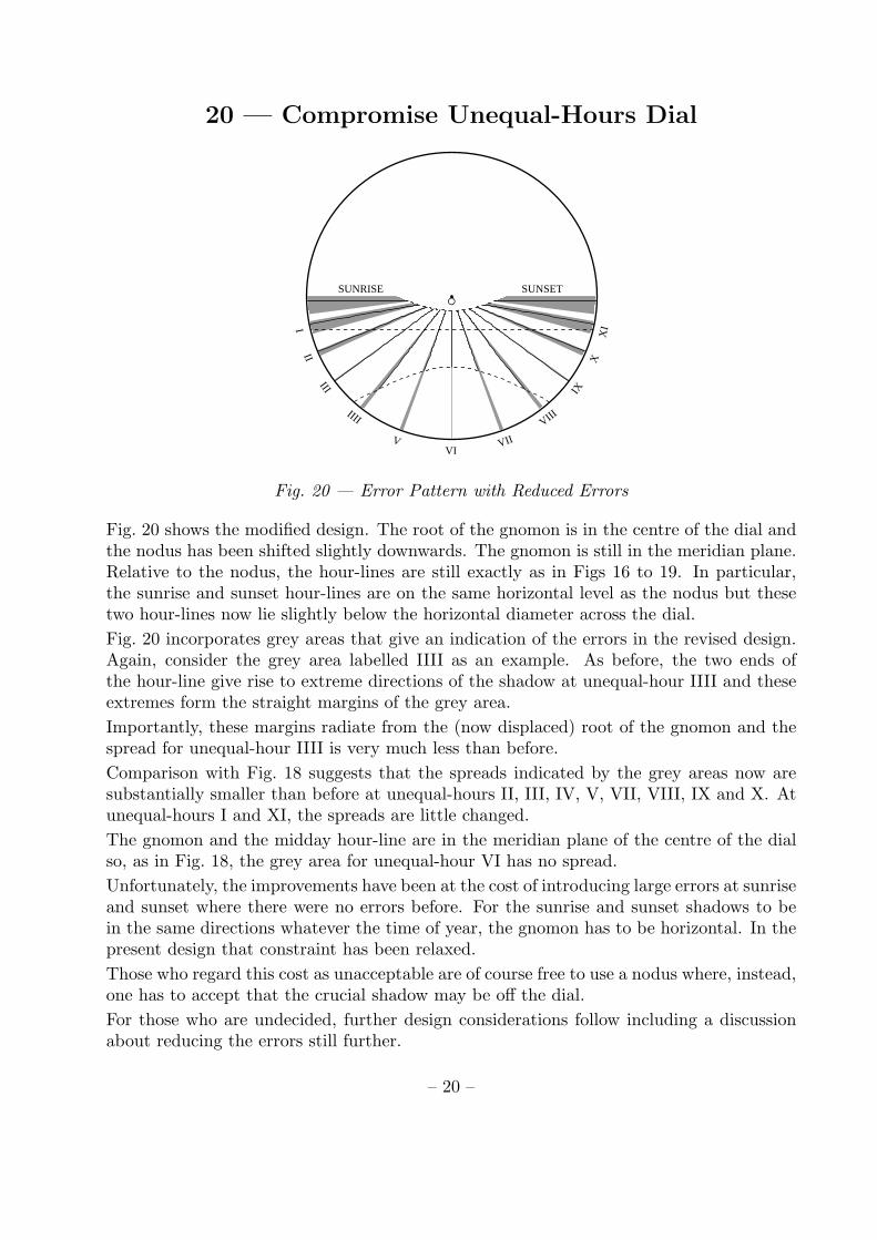
Fig. 20 — Error Pattern with Reduced Errors
Fig. 20 shows the modified design. The root of the gnomon is in the centre of the dial andthe nodus has been shifted slightly downwards. The gnomon is still in the meridian plane.Relative to the nodus, the hour-lines are still exactly as in Figs 16 to 19. In particular,the sunrise and sunset hour-lines are on the same horizontal level as the nodus but thesetwo hour-lines now lie slightly below the horizontal diameter across the dial.
Fig. 20 incorporates grey areas that give an indication of the errors in the revised design.Again, consider the grey area labelled IIII as an example. As before, the two ends ofthe hour-line give rise to extreme directions of the shadow at unequal-hour IIII and theseextremes form the straight margins of the grey area.
Importantly, these margins radiate from the (now displaced) root of the gnomon and thespread for unequal-hour IIII is very much less than before.
Comparison with Fig. 18 suggests that the spreads indicated by the grey areas now aresubstantially smaller than before at unequal-hours II, III, IV, V, VII, VIII, IX and X. Atunequal-hours I and XI, the spreads are little changed.
The gnomon and the midday hour-line are in the meridian plane of the centre of the dialso, as in Fig. 18, the grey area for unequal-hour VI has no spread.
Unfortunately, the improvements have been at the cost of introducing large errors at sunriseand sunset where there were no errors before. For the sunrise and sunset shadows to bein the same directions whatever the time of year, the gnomon has to be horizontal. In thepresent design that constraint has been relaxed.
Those who regard this cost as unacceptable are of course free to use a nodus where, instead,one has to accept that the crucial shadow may be off the dial.
For those who are undecided, further design considerations follow including a discussionabout reducing the errors still further.
– 20 –

21 — Compromise Unequal-Hours Dial
SUNRISE SUNSET
III
III
IIII
VVI
VII
VIII
IX
XX
I
Fig. 21 — Error Pattern with Best-Fit Straight Lines
In Fig. 21, the unequal-hours hour-lines of the previous figures have been replaced bystraight lines which radiate from the root of the gnomon. All these compromise hour-linesextend to the rim of the dial.
It was suggested earlier (in the context of Fig. 8) that the hour-lines might be drawn inthe mid-range positions (along the centres of the grey areas). It was added that this is aslightly naıve approach and the procedure used in Fig. 21 is as follows:
1. For each unequal-hour, calculate the angle of the shadow of the gnomon (relative tothe upward vertical) at that unequal-hour for every day of the year.
2. Omit any values that apply to days when the sun is shining on the wrong side of thewall at the unequal-hour in question.
3. Determine the mean of the 365 (or fewer) values calculated.
4. Choose that mean as the angle for the hour-line.
5. Draw the hour-line so that it extends from some aesthetically-chosen circle round theroot of the gnomon to the rim of the dial.
The hour-lines which result are fairly close to the mid-range positions. Hour-line VI is theonly one for which the error range is zero and, unsurprisingly, the error range for unequal-hours III and IX are close to zero because of the way these times were used to determinethe position of the root of the gnomon.
– 21 –

22 — Compromise Unequal-Hours Dial
III
III
IIII
VVI
VII
VIII
IX
XX
I
Fig. 22 — Complete Outline Compromise Unequal-Hours Dial
In Fig. 22 the constant declination lines and the grey areas have been dispensed with. Thisis a complete outline design for an unequal-hours sundial where the time is indicated bythe direction of the shadow of the gnomon.
A designer would be free to change the shape of the dial and may use long hour-lines orshort tick-marks but the orientation of the gnomon and the directions of the hour-linesmust be as dictated by the procedure which has been outlined above.
No indication of errors are included in this outline design but a designer may wish todisplay the ranges in some way.
The error ranges are greatest for the sunrise and sunset hour-lines. The downward slopesof the compromise hour-lines for sunrise and sunset are something of a give-away andthese lines are omitted from the Newnham College Dial. In their place there are two wavysun-rays which hint at the unreliability of the instrument at these times!
The analysis so far has assumed a direct south-facing dial. In fact, the Newnham CollegeDial faces a few degrees west of due south. In dialling terminology it is said to decline3◦13′ 6′′ to the west.
It is necessary to have a short discussion about declining dials before adapting the aboveprocedure for the Newnham College Dial. . .
– 22 –

23 — Declining Compromise Unequal-Hours Dial
R1
R0
Fig. 23 — A Primitive Dial that Declines to the West
Fig. 23 shows the dial of Fig. 11 rotated about its vertical centre-line so that it now facesa little to the west of due south. The gnomon has not been carried along with the dial andcontinues to be in the meridian plane of the centre of the dial. Accordingly it is horizontaland points due south.
The north pointer is exactly as in Fig. 11 and the gnomon is parallel to this pointer.Although it is still horizontal, the gnomon is no longer perpendicular to the plane of thedial. The perpendicular from the tip of the gnomon (the centre of the nodus) to the dialintersects the dial at a point which is marked with a small dot.
Given that the gnomon is horizontal, the shadow at sunrise and sunset will always behorizontal. Given that the gnomon lies in the meridian plane, the shadow at midday willalways be vertical. The three cardinal unequal-hours hour-lines of Fig. 5 are still valid. Ofthese, only the midday hour-line for unequal-hour VI has been drawn in Fig. 23.
The gnomon has to be horizontal for the sunrise and sunset shadows to be in the samedirection whatever the time of year and the gnomon has to be in the meridian plane forthe midday shadow to be in the same direction whatever the time of year.
Unfortunately, these hard constraints lead to the large errors indicated by the grey areasof Fig. 8. By relaxing the constraint that the gnomon must be horizontal, most of theerrors can be reduced but at the cost of introducing errors at sunrise and sunset.
In Fig. 23 hour-line VI has been extended upwards as a thin line drawn along the verticalcentre-line of the dial. The root of the gnomon is currently in the centre of the dial at R0.If the tip of the gnomon and nodus are kept fixed but the root of the gnomon is moved upthe centre-line to some well-chosen point R1, the gnomon will no longer be horizontal butit will still be in the meridian plane. The goal is to find a good position for R1.
– 23 –

24 — Declining Compromise Unequal-Hours Dial
SUNRISE SUNSET
I
II
III
IIII
VVI VII
VIII IX
X
XI
Fig. 24 — Constructing Compromise Unequal-Hours Hour-Lines for a Declining Dial
Fig. 24 shows Fig. 19 adapted for a wall that declines 3◦13′ 6′′ to the west. The root of thegnomon is indicated by a black dot. This is in the centre of the dial, R0 in Fig. 23. Thegnomon is horizontal and in the meridian plane but it is not perpendicular to the dial.That is why the centre of the nodus is shown slightly to the right of the black dot.
Fig. 24 is again very close to being a gnomonic projection of Fig. 3 but, using the pin-holecamera analogy, the camera is no longer pointing due south. Accordingly, the image onthe plate is slightly different from that in Fig. 19.
The equinoctial line now slopes slightly upwards to the east (right) and will intersect thesunset hour-line a finite distance from the centre of the dial rather than at infinity.
Notice that hour-line VI aligns with the root of the gnomon and not with the nodus. Thisis simply a consequence of hour-line VI on the celestial sphere aligning with the southmarker on the horizon. Hour-line VI on the celestial sphere, hour-line VI on the dial, thegnomon and the nodus are all in the meridian plane of the centre of the dial.
Two straight broken lines have again been drawn, in red, through the triplets of points forunequal-hours III and IX. As in Fig. 19 these lines intersect at a point a little above theroot of the gnomon.
On the celestial-sphere the equivalent point is on the meridian a little below the horizon(underneath the south marker). The point of intersection, the south marker and themidday hour-line are all on the meridian so they all align when projected onto the dial.
The point of intersection on the dial can be used as a revised position, R1, for the root ofthe gnomon. It is much closer to R0 in the centre of the dial than is suggested in Fig. 23.In elevation, the line from the point of intersection to the centre of the nodus is very shortand inclined to the vertical. It is, though, in the meridian plane.
– 24 –

25 — Declining Compromise Unequal-Hours Dial
SUNRISE SUNSET
III
III
IIII
VVI
VII
VIII
IX
XX
I
Fig. 25 — Error Pattern with Reduced Errors for a Declining Dial
Fig. 25 is the equivalent of Fig. 20 for a wall that declines 3◦13′ 6′′ to the west. As whenpreparing Fig. 20, instead of moving the root of the gnomon to the point of intersection ofthe red lines in Fig. 24, the nodus has been shifted downwards by an equivalent amount.
Relative to the nodus, the hour-lines are still exactly as in Fig. 24. In particular, thesunrise and sunset hour-lines are on the same horizontal level as the nodus but these twohour-lines now lie slightly below the horizontal diameter across the dial.
The hour-lines in the figure are those determined by considering the shadow of the nodusrather than the shadow of the gnomon. They are narrow S-shapes. Straight lines canbe drawn from the root of the gnomon to points along the length of a given hour-line todetermine the spread of directions taken by the shadow of the gnomon at the unequal-hourof interest.
Fig. 25 incorporates grey areas that give an indication of the errors. They are very muchas in Fig. 20. There is no spread at unequal-hour VI, almost no spread at unequal-hoursIII and IX and very little spread at unequal-hours II, IIII, V, VII, VIII and X. It is onlyat sunrise and sunset that the spread is significant.
– 25 –

26 — Declining Compromise Unequal-Hours Dial
SUNRISE SUNSET
III
III
IIII
VVI
VII
VIII
IX
XX
I
Fig. 26 — Error Pattern with Best-Fit Straight Lines for the Declining Dial
In Fig. 26, the unequal-hour hour-lines of the previous figures have been replaced bystraight lines which radiate from the root of the gnomon. All these compromise hour-linesextend to the rim of the dial.
The procedure used for determining the orientations of the compromise hour-lines is asdescribed for Fig. 21. The hour-lines are close to the mid-range positions (along the centresof the grey areas).
The wide variability of direction of the shadow of the gnomon at sunrise and sunset isunquestionably a design weakness but it is a weakness with little practical consequence.The Newnham College Dial does not have a clear view of the horizon in any direction sothe gnomon never casts a shadow at sunrise or sunset!
The same practical consideration applies only a little less strongly at unequal-hours Iand XI which are the other two times where the direction of the shadow may be appreciablyin error. During the summer months the sun shines on the wrong side of the wall at thesetimes and during the winter months the sun is so low that, again, the gnomon does notcast a shadow.
– 26 –

27 — Declining Compromise Unequal-Hours Dial
III
III
IIII
VVI
VII
VIII
IX
XX
I
Fig. 27 — Complete Outline Declining Unequal-Hours Dial
In Fig. 27 the constant declination lines and the grey areas have been dispensed with.This is a complete outline design for the Newnham College Dial and is appropriate for thelatitude of the site (52◦ 11′ 58′′ N) and the orientation of the wall (declining 3◦13′ 6′′ to thewest).
This design is a first attempt to approximate the impossible goal of an unequal-hourssundial where the time is indicated by the direction of the shadow of the gnomon.
The procedure described above leads to a gnomon which lies in the meridian plane (ensuringthat the shadow is vertically downwards at midday) and whose orientation is specified thus:
• Offset from normal to the dial is 9.15◦
• Offset of projection onto the dial from the downward vertical is 20.43◦
Diallists often refer to the projection of a gnomon onto a dial as the sub-style and the secondvalue as the sub-style angle. The sub-style of a polar-oriented gnomon is perpendicular tothe equinoctial line. That is not the case with this gnomon. The style height is 80.85◦,the complement of the first value.
Arranging the hour-lines so that they radiate to the edge of a circular dial, echoes thescheme which is commonly found on the Mass Dials that Margaret Stanier took someinterest in.
Each hour-line is in the mean direction of the shadow of the gnomon at the unequal-hourindicated. This is the mean of 365 directions over a year.
The development of the design is described later but a practical point of note is that thelength of the gnomon has to be much greater (relative to the dimensions of the dial) thanthe length of a conventional polar-oriented gnomon. At midday in winter, the sun is lowand a nearly-horizontal gnomon casts a very short shadow onto a vertical dial.
– 27 –

28 — Hour-Line Angles of Best-Fit
Fig. 28 — Point-by-Point View of Unequal-Hour Hour-Line III
Fig. 28 shows how hour-line III in Fig. 24 might be established experimentally as a sequenceof points. The large dot at lower left is the position of the shadow of the nodus at unequal-hour III on the day of the summer solstice. Subsequent small dots show the position of theshadow at the same hour at two-day intervals until the winter solstice. Two more largedots mark the positions at the autumnal equinox and at the winter solstice.
Almost as before, a red construction line has been drawn through the large dots. In Fig. 24,the summer solstice dot was omitted because it is outside the confines of the dial.
The red construction line can be regarded as an axis of the S. The small dots lie slightlyto one side or the other of this axis. To emphasise the shape, the extent by which eachdot is off-axis has been exaggerated by a factor of 20. Even so, the S is very thin. It is notsurprising that unequal-hour hour-lines are sometimes drawn straight.
The asymmetry of the S-shape is an artefact of the gnomonic projection which also accountsfor the dots crowding on top of one another at the upper end of the S.
As noted in the context of Fig. 16, the S-shape on the celestial sphere has rotationalsymmetry. If it is rotated 180◦, it matches the unrotated original. Although the shapeis symmetrical, the arrangement of day-by-day points is not. There are more days (andhence more dots) between the summer solstice and the vernal equinox than between thevernal equinox and the winter solstice. This is because the Earth is further from the sunin summer.
Just off the upper end of the S there is a tiny circle and dot. These are, respectively, thenodus and the point where the red lines intersect in Fig. 24. This point of intersectionis R1, the root of the gnomon in the design that has been described. As in previous figuresthe nodus is shown in elevation; it is not in the plane of the dial,
The point of intersection aligns, by construction, with the three large dots but it cannotbe assumed that the line through the three dots is the best-fit hour-line. . .
– 28 –

29 — Hour-Line Angles of Best-Fit
R1
N
Fig. 29 — The Upper End of Unequal-Hour Hour-Line III
The dots that contribute to the S-shape in Fig. 28 are shown for every alternate day andfor only half the year. If shown in full, the S in Fig. 28 would have 365 dots. The dots forthe period from the winter solstice back to the summer solstice lie on the same S-shape.These extra dots do not complete an analemma-like figure-of-eight; they just contributeadditional dots to the S.
Fig. 29 shows an expanded version of the upper end of Fig. 28 still with only a quarter ofthe full quota of dots. The positions of the root of the gnomon and the nodus are labelledR1 and N respectively.
The procedure for determining the orientation of hour-line III is as described for Fig. 21.From R1, a line is drawn to each of the 365 points that contribute to the S-shape and theangle of each line is measured relative to the upward vertical.
The mean, m, of the 365 values is the angle used for drawing the hour-line and the standarddeviation, s, of the 365 values give a measure of the angular spread, the error inherent inthe design. In the case of hour-line III, s = 0.198◦.
The result is deemed the best-fit hour-line III from R1. It runs a little above the tripletof points that determine the red construction line and is offset from that line by an angleof 0.027◦. The off-axis dots on the winter half of the S are nearer the root of the gnomonthan the off-axis dots on the summer half and bias the angle upwards.
The procedure for determining the orientation of each of the other hour-lines is exactlythe same. From R1, a line is drawn to each of the (up to) 365 points that contribute tothe relevant S-shape; the mean angle is used for the hour-line and the standard deviationgives a measure of the angular spread.
For about half the year, the sun shines on the wrong side of the wall in the early morningand in the late afternoon and for the associated hour-lines fewer than 365 dots apply.
The set of standard deviations for all 13 hour-lines provides a means of assessing how muchof an improvement results from moving the root of the gnomon to R1 and also provides ameans of determining whether there is a better position.
– 29 –

30 — Hour-Line Angles of Best-Fit
R2
R1
Fig. 30 — RMS Errors for Different Gnomon Orientations
To illustrate some of the observations just made, Fig. 30 shows hour-line III distorted fromthe S-shape into a symmetrical zig-zag which has simpler geometry. The zig-zag has largedots at its mid-point and at its extremities.
The large dots are aligned as in Fig. 28 and a red construction line has been drawn throughthem. A similar line may be drawn through the three dots of hour-line IX but is not shown.The two construction lines intersect at R1 which is on the the vertical centre-line of thedial (shown as the vertical line in the figure). Point R1 is again the root of the gnomonbut the 365 dots that make up the S-shape have been displaced to form the zig-zag.
Although the zig-zag is itself symmetrical, the angles made by the lines from R1 to theunshown points which constitute the zig-zag are not symmetrically distributed either sideof the red construction line. Two extreme cases are shown as blue lines through R1 andthe angles these lines make to the red construction line are clearly not equal and opposite.
The mid-range position is shown as a broken blue line. The mean value would be closerto the red construction line but would still not be coincident with it.
Point R2 in the figure is higher up the vertical centre-line than R1 and the two new extremesare again shown as blue lines. The angle between these blue lines is less than the anglebetween the blue lines from R1. If R2 is raised still further, the angle between the extremesincreases though it will eventually start falling again. As R2 tends to infinity, the spreadapproaches zero but this is not a useful position for the root of the gnomon.
By experiment, using the 365 dots that make up the actual hour-line III of Fig. 24, it canbe shown that an equivalent point R2 can be found from which the standard deviation is alocal minimum for hour-line III on the Newnham College Dial. This value is 0.157◦ whichis a small improvement over 0.198◦, the standard deviation associated with R1.
Since R2 gives rise to a local minimum standard deviation for hour-line III, it is a newcandidate position for the root of the gnomon. Before adopting this new position, it isprudent to see how the standard deviations of the other hour-lines are affected.
– 30 –

31 — Hour-Line Angles of Best-Fit
= R0 = R1 = R2
0 1 2 3 4 5 6 7 8 9 10 11 12
Unequal-Hours
0.0
1.0
2.0
3.0
4.0
5.0
Stan
dard
Dev
iatio
n in
Deg
rees
Fig. 31 — Errors for Different Gnomon Orientations
For each of three orientations of the gnomon Fig. 31 shows, for each unequal-hour hour-line,the standard deviation of the angles of the shadow of the gnomon at that unequal-hour.
The open circles show the standard deviations when the gnomon is horizontal, as in Figs 23and 24. There are no errors at sunrise, midday and sunset (unequal-hours 0, 6 and 12 inthe figure) but there are large errors at all other times.
The crosses show the standard deviations when the root of the gnomon is in the R1
position, as in Figs 25 to 26. There is again no error at midday and, compared withhaving a horizontal gnomon, the errors are much reduced at unequal-hours 2, 3, 4, 5, 7, 8,9 and 10. There is a marked deterioration at sunrise and sunset and a small deteriorationat unequal-hours 1 and 11.
The dots show the standard deviations when the root of the gnomon is in the R2 position.Once again there is no error at midday and, by construction, the errors at unequal-hours 3and 9 are the minimum possible but they are only a little less than when the R1 positionis used. Compared with the R1 position, the errors are slightly reduced at unequal-hours3, 4, 5, 7, 8, 9 and slightly worse at 0, 1, 2, 10, 11, 12.
It was taken as a hard constraint that the gnomon should lie in the meridian plane.This ensures that there are no errors at unequal-hour VI, halfway through the solar day.Choosing the angle for the gnomon to make to the horizontal offers scope for debate. . .
Unequal-hours III and IX seem next in importance to unequal-hour VI in that they quarterthe solar day. Analysis of the shadow of the gnomon at these times suggested two possibleangles of dip, 8.57◦ and 8.90◦, the angles associated with points R1 and R2 respectively.
– 31 –

32 — Hour-Line Angles of Best-Fit
III
III
IIII
VVI
VII
VIII
IX
XX
I
Fig. 32 — Comparing two Designs
Fig. 32 compares the two candidate positions, R1 and R2, for the root of the gnomon in asingle composite design. Red relates to R1 and blue relates to R2.
The centre of the dial is used as the common root for both gnomons. The nodus is shownsplit into two. The left-hand, red, half is on the tip of the gnomon whose angle of dipis 8.57◦ and the right-hand, blue, half is on the gnomon whose angle of dip is 8.90◦.Accordingly, the blue half is very slightly lower than the red half.
Likewise there are red hour-lines and blue hour-lines both drawn as broken lines. Thedifferences between the two sets of lines can be seen only by very close inspection. Themaximum differences are less than the thickness of the drawn lines. Fig. 31 shows thatfrom unequal-hour 2 to unequal-hour 10, the standard deviation is always well below 1◦
which very roughly translates into four ordinary minutes.
For the Newnham College Dial, the R1 choice was made, partly on the grounds that it iseasier to describe the construction that establishes the position of R1 and partly becauseit leads to a slightly better performance at the early morning and late afternoon hours.These are the times when using a nodus is most unsatisfactory because the shadow is likelyto be off the dial.
In passing, it should be noted that unequal-hours III, VI and IX not only quarter the daybut they are also nominally associated with the Christian Offices of Terce, Sext and Nonewhich were important to users of Mass Dials. At these times, the standard deviation inboth designs is always less than 0.2◦ which translates into rather less than one ordinaryminute.
– 32 –

33 — Evolution of the Design
Fig. 33 — The South Wall of the Rosalind Franklin Building
The proposal for a sundial as a memorial for Margaret Stanier was first aired in an e-mailfrom Dr Claire Barlow, Fellow in Engineering at Newnham College. This was sent on25 October 2008:
Newnham has £11k to spend on Public Art, with a short timeframe
for decision. What chance of a Peggy Stanier Memorial sundial
at the end of the Rosalind Franklin Building on Newnham Walk?
Could we discuss?
Rosalind Franklin played a crucial role in the analysis of DNA and ranks as one of themost distinguished former students of the College. The long axis of the building namedafter her runs north-south and on each end wall there is a square stone panel made fromlimestone blocks. Each panel sits in a slight recess in the surrounding brickwork and isornamented by a faux balcony which can be seen in the photograph in Fig. 33.
Interestingly, the balcony rail is supported at its centre by a horizontal bracket which isperpendicular to the stonework. It thereby serves as a traditional horizontal gnomon. Thebracket cannot be seen in the photograph but its shadow shows up as a short diagonalelement running downwards to the right.
The rectangular space above the rail is almost ideal for a sundial since it is close to directsouth-facing. The space invites the use of a rectangular slab of slate for the dial but, to gosome way towards echoing the circular shape of most Mass Dials, it was decided to roundoff the corners and implement a design on an ellipse.
– 33 –

34 — Evolution of the Design
IN M
EMORIAM MARGARET W STANIERDIALLIST
I
II
III
IV
VVI
VII
VIII
IX
X
XI
SUNRISE SUNSET
Fig. 34 — A very rushed first Design
After an enjoyable meeting, the College expressed interest in an unequal-hours sundial andasked for a report which should include an outline design. The report was needed in ahurry and the submitted design is shown in Fig. 34. At this stage the orientation of thewall was not known to high precision. It was assumed that it declined 3◦ to the west.
Not all of the foregoing theory was used. The gnomon was in the meridian plane and dippeddownwards at an angle dictated by point R1 but the angles of the hour-lines were chosensimply by calculating the positions of the shadow of the gnomon at the 13 unequal-hourson a day when the solar declination was −2◦.
Had the wall been direct south-facing, the positions on the day of an equinox would havebeen used but, at the equinoxes, the sun is behind the declining wall at sunrise.
The design includes a chapter ring for the hour-labels and an inscription. No guidance hadbeen given about the inscription at this stage so some text was invented. The sun in thefigure was straight plagiarism; it is a copy of the sun in the Queens’ Dial.
Several features suggested by this outline survived the entire design process. The finisheddial is on an elliptical slab of slate and all the dial furniture is cut into the slate and gilded.The hour-lines are labelled with Roman Numerals and there are half-hour markings too.
In Fig. 34 the gnomon is white simply to ensure that it stands out against the background.The gnomon is shown in elevation and, given that it dips only a few degrees below thehorizontal, the figure is implying that the gnomon is extraordinarily long!
– 34 –

35 — Evolution of the Design
Fig. 35 — Surveying the Site
These days, establishing the orientation is of a wall is most conveniently undertaken byusing highly specialised surveying kit which exploits the Global Positioning System (GPS).Hurst Surveys of Toft undertook this work.
The College erected some scaffolding and the surveyors put four short strips of reflectivetape on the panel of stone. In the photograph in Fig. 35, one of the two surveyors isstanding on the scaffolding looking at the tripod which was used to support the GPSreceiver.
Via an adapted mobile telephone, the equipment communicates with an Ordnance Surveyreference site. This site returns information which enables the GPS receiver to refine thedata received from the GPS satellites.
After processing, Hurst Surveys supplied the eastings and northings of the centre-markson two strips of reflective tape which were at the same horizontal level on the stone panel.The coordinates were given in millimetres relative to the Ordnance Survey grid referencepoint about 50 miles to the west of the Scilly Isles.
The azimuth of the stonework relative to Grid North can readily be computed from thesecoordinates and, with a little more processing, the azimuth relative to True North can bedetermined. The principal site parameters are:
Latitude = 52◦ 11′ 58′′ N
Longitude = 0◦ 6′ 35′′ E
Azimuth of outward normal = 183◦ 13′ 6′′
– 35 –

36 — Evolution of the Design
IN M
EMORIAMMARGARET W STANIER
DIALLIST
I
II
III
IV
VVI
VII
VIII
IX
X
XI
SUNRISE SUNSET
Fig. 36 — A First Refinement
Determining a set of angles for the hour-lines of a sundial is really just the start of thedesign process. A second challenge is to produce an instrument which looks good too!
Fig. 36 shows a first refinement of the design in the report to the College. The Queens’Dial sun has been replaced by a version which has alternating wavy rays and spiky rays.These two forms of ray are sometimes said to represent heat and light respectively.
Notice that there are 11 sun-rays which, with the 13 hour-lines, makes a total of 24 radialelements. This total is loosely in keeping with some Mass Dials that have 24 hour-lines atroughly 15◦ intervals round the circle.
The angles of the hour-lines now accord more with those in Fig. 27; the sunrise and sunsetlines are at angles that embarrassingly draw attention to the consequences of relaxing theconstraint on the gnomon having to be horizontal. The chapter ring is unchanged but thelength of the gnomon implied by this new view in elevation is much more realistic. Thegolden circle represents the gnomon support.
This first refinement is a long way from being satisfactory but it was sufficient for theCollege to give the go-ahead to order the slate. This was supplied by Ivett & Reed, awell-known stone-yard in Cambridge. They were provided with a full-size template, anellipse whose major axis was 1065mm and whose minor axis was 865mm. The specifiedthickness was 36mm.
Ivett & Reed were asked to supply memorial quality blue-grey Welsh slate and to checkthat it was free of blemishes and also free of Iron Pyrites, sometimes called Fool’s Gold.This is a common impurity in slate, which can look a little like gold, but when exposed tothe elements it turns a rusty brown and discolours the slate.
– 36 –

37 — Evolution of the Design
Fig. 37 — The Bell-Shaped Gnomon Support
Margaret Stanier was well known in Cambridge bellringing circles so incorporating a littlebell was thought appropriate. The bell was used to support the gnomon as shown inFig. 37.
The figure shows a cross-section of a small part of the slate with a recess cut into the underside for a base-plate. The bell is mounted on the upper side and held in place by boltsthat run through the base-plate and slate.
The shape is based on the normal profile used by the bellfounders John Taylor & Co. ofLoughborough but it is elongated slightly and so does not have the same proportions as areal bell. The bell is 80mm in diameter at its base and is 80mm high.
An inclined hole is drilled through the bell to accommodate the gnomon which is in theform of a circular rod 8mm in diameter and 400mm long. The centre of the lower end ofthe gnomon coincides with the centre of the base of the bell.
The cross-section in the figure is along the sub-style and the gnomon is offset 9.15◦ fromthe perpendicular or, in dialling terminology, the style height is 80.85◦. The faces of theslate on the finished sundial are, of course, vertical but the gnomon is offset 8.57◦ from thehorizontal, not 9.15◦. The difference is accounted for by the sub-style being offset 20.43◦
from the downward vertical.
The gnomon components were all made in marine grade stainless steel (grade 316) byTeversham Engineering Ltd of Cambridge. Later, the bell and gnomon were gold-platedby Modern Metal Finishes Ltd of Hull.
– 37 –

38 — Evolution of the Design
IN M
EMORY OF MARGARET STANIERSUNRISE SUNSETSCIENTIST
D IA L LI S T
Fig. 38 — A Scheme incorporating Suggestions by Annika Larsson
From this stage to the finish, almost all the design and manufacture was in the hands ofAnnika Larsson who runs Inscriptorum a noted Swedish Design Workshop.
Annika had been sent the report to the College and had seen the designs in Figs 34and 36. She made numerous comments and there was a considerable volume of e-mailtraffic between Cambridge and Sweden. She pointed out that, with the natural view pointabout 10m from the slate, the lettering would have to be much larger and heavier.
Fig. 38 shows an adaptation of one of Annika’s early proposals. The chapter ring has beenchanged to a gilded band which has ungilded raised lettering for the inscription and forthe hour labels. The IV has been replaced by IIII which balances the VIII better. Thehalf-hour lines are now tipped by diamonds which grow during the morning hours and thenfade in the afternoon. The centres of the diamonds lie in a circle rather than an ellipse.
The inscription has been changed from Latin into English and the sun has been replaced bylettering which extends the inscription. Annika’s plan was to have strongly spiky letteringwhich would look like rays of the sun. The annotations SUNRISE and SUNSET have survivedbut there are no sunrise and sunset hour-lines.
While this proposal was being developed, the College was also giving thought to the design.A refinement of Fig. 38 was submitted for consideration but was not taken up. The Collegepreferred the more conventional sun of Fig. 36 and asked to have the inscription at thebottom of the slate rather than at the top.
This last requirement seemed quite a tall order and Annika paid a visit to Cambridge forsome face-to-face discussions. . .
– 38 –

39 — Evolution of the Design
Fig. 39 — The Starbucks Sketch
Monday 12 October 2009 turned out to be a memorable day. The plan was for Annika togo to Newnham College for lunch followed by a meeting to discuss the design. It seemedprudent to have a pre-meeting meeting to ponder how the inscription might be moved tothe bottom. This preliminary meeting took place in the Grand Arcade Starbucks in theCity Centre.
Annika had no firm ideas and, despite a considerable amount of doodling on table napkins,there was little progress. Then, just as the coffee was getting cold, she had an idea. Shewalked over to the large window in the front of the cafe and used it as an improvisedtracing table. After five minutes she came back with a sketch which she later tidied upinto what is shown in Fig. 39.
The inscription is duly at the bottom and follows the margin of the ellipse. The outer endsof the hour-lines are now bounded by a circle and are therefore much more in keeping withthe hour-lines on Mass Dials.
The half-hour markings have been reduced to diamonds and they and the hour labelsfollow the circle that bounds the ends of the hour-lines.
The annotations SUNRISE and SUNSET have gone and there are no hour-lines for sunriseand sunset and no half-hour diamonds before I and after XI.
The two horizontal sun-rays are shown as trial alternatives. Do we want them to look likehour-lines as the one of the left or to look like spiky rays as the one on the right?
After some discussion it was decided to use neither. In the final design, both the horizontalrays are wavy, reflecting the rather wayward behaviour of the sundial at sunrise and sunset!There are also 13 sun-rays in the final design rather than 17.
– 39 –

40 — Evolution of the Design
M A
R G A R E T S T A N I E RS C I E
N T
I S T
Fig. 40 — Ready for Marking out
Fig. 40 shows the construction lines which were used for setting out the design on the slate.The most important reference lines are the major and minor axes of the slate itself. Thosewho work on elliptical plaques call this the Big Cross. A secondary crucial reference line isthe horizontal line, parallel to the major axis, through the root of the gnomon. The rootof the gnomon is at the centre of the gold circle which represents the base of the bell.
The ellipse shown as a broken line is the only true ellipse in the figure. The top line andthe base line of the inscription are drawn parallel to this reference ellipse and are not trueellipses. The outer margin of the slate itself is also parallel to the reference ellipse so eventhe slate is not quite in the shape of a true ellipse.
Most of the remaining guidelines are arcs of circles centred on the root of the gnomon orlines radiating from the same centre. Two of the arcs form the top line and base line of thehour labels. The middle arc of the triplet of arcs marks the outer margin of the hour-linesand the centre-line of the half-hour diamonds. The outer arcs of the triplet mark the topline and bottom line of the tallest half-hour diamonds either side of hour-line VI.
The gnomon, shown in elevation (and now gold), indicates the direction of the sub-stylewhich almost coincides with hour-line VII but not quite. The dot between STANIER andSCIENTIST has been contrived to lie precisely on the sub-style!
The broken straight line is the equinoctial line that applies to the tip of the 400mm-longgnomon. By another contrivance, this line is tangential to the circle that marks the outermargin of the hour-lines. The equinoctial line is not at right-angles to the sub-style.
The three golden open circles are discussed in the context of Fig. 42 and the guidelines forthe sun-rays are discussed in the context of Fig. 47.
– 40 –

41 — Construction
Fig. 41 — Annika Larsson using Rubbing Wax
The photograph in Fig. 41 shows a corner of Ivett & Reed’s stone store with the slateplaced on a pallet. Annika has laid some tracing paper over the slate and this is held downby a roofer’s square.
The first task is to mark out the Big Cross and this is surprisingly difficult. The slate isnot supplied with the major and minor axes neatly marked out. Conventional geometricalprocedures are not as useful as theory would suggest and the standard practice is to drawan outline of the slate on tracing paper and then fold the paper in half both ways so thatthe two creases form a cross. This is then transferred to the slate.
In the figure, Annika is holding a stick of black rubbing wax and is about to work all roundthe edge of the slate. The result should be a closed black curve on the tracing paper.
The paper is then folded approximately along the minor axis and held up to the light sothe two ends of the major axis lie on top of one another. With a bit of fiddling, the twoends can be persuaded to coincide and the fold in the paper is then pressed flat. The creaseshould run along the minor axis.
The paper is then opened up and the procedure is repeated to establish the major axis.The paper is opened up again and laid back on the slate. Short lines are drawn on theslate at the four ends of the two axes. The paper is then removed and the two pairs ofends joined up to form the Big Cross. The Big Cross is rarely right first time and thewhole task may have to be repeated. Numerous measurements are made as checks.
The slate shape was also marked out on heavy-duty card and heavy-duty plastic. The cardwas used as a template for drilling holes in the slate and the plastic, with edgings, wasfashioned into a lid which protected the surface when the slate was not being worked on.
– 41 –

42 — Construction
Fig. 42 — Mark Taylor who made the Gnomon
The next task was to mark out the positions of six holes which were to be drilled in theslate. Three holes 15mm in diameter were to be drilled 20mm into the back of the slatefor 14mm diameter fixing-dowels. The positions of these holes are shown as open goldcircles in Fig. 40 and these positions were marked on the card template. These holes donot go right through the slate.
Three more holes were to be drilled right through the slate for the M6 bolts which runthrough the base-plate, through the slate and into the gnomon support.
The plan was to use Ivett & Reed’s high-quality drilling equipment and, to save taking theslate away and bringing it back, the early marking out was carried out on their premises.
It made sense to delay marking out the holes for the gnomon support until the positionsof the tapped holes in the bell-shaped support were known. It was time to pick up thegnomon. . .
In the photograph in Fig. 42, Mark Taylor of Teversham Engineering is holding the newgnomon. Mark undertook all the turning and assembly and he is about to hand over thefinished product.
The original design, in Fig. 37, had a central bolt and three peripheral bolts arrangedin a Y-shape. The central bolt was dispensed with so only three holes had to be drilledthrough the slate. These were drilled oversize so that there was some leeway when it cameto aligning the gnomon along the sub-style.
– 42 –

43 — Construction
Fig. 43 — Annika Larsson cutting the Recess for the Base-Plate
With the six holes duly drilled, the slate was taken to a spare bedroom which had beenconverted into an improvised workshop. This is shown in the photograph in Fig. 43. Theslate has been placed face down on a work table and Annika is cutting the recess for thebase-plate which can be seen on the slate near a scriber.
The other item on the slate is a Caran d’Ache PrismaloTM pencil. This is white, fordrawing on slate, and is water soluble so markings can easily be washed off.
Ivett & Reed were asked to hone one face and the rim of the slate but it is unnecessaryto rub the back of the slate to a fine finish. This is why scratches and irregular reflectionscan be seen in the photograph.
A honed surface is very smooth but not polished. This leads to a good shadow withoutunwanted reflections. To protect the honed face, the work table was covered in a strip ofcarpet and the face of the slate was covered with a protective plastic cover. The maskingtape that secures the cover can be seen along the lower edge of the slate.
The gnomon with its bell-shaped support is on the dressing-table mirror at the foot of thebed. Two of the three holes for the fixing-dowels can be seen in the slate and the threeholes for the bolts that secure the gnomon are also clear in the recess.
At the foot of the bed there is the elliptical template which was used for marking outwhere the holes were to be drilled for the fixing-dowels. The same template would be usedlater for marking the positions of the holes to be drilled into the wall where the dial wasto go. On the right there is an easel which would support the slate at a later stage.
Unsurprisingly, cutting slate generates a good deal of fine dust. This accounts for Annika’sheadgear.
– 43 –

44 — Construction
Fig. 44 — Aligning the Gnomon along the Sub-Style
After the recess for the base-plate was finished, the slate was turned face upwards. TheBig Cross was augmented by the secondary reference line that runs through the root ofthe gnomon parallel to the major axis, and a circle matching the base of the bell-shapedsupport was drawn. The sub-style was drawn next. This runs from the root of the gnomonand makes an angle a little over 20◦ to the downward vertical; it is close to hour-line VII.
The slate was then arranged to bridge a gap between two tables so that the base-platecould be put into its recess from below. The three bolts were screwed through the gnomonsupport into the base of the gnomon but the bolts were left only finger-tight.
The plan was to turn the bell on its base slightly one way or the other until the projectionof the gnomon onto the dial ran along the sub-style. One side of a roofer’s square was laidalong the sub-style and the other side was held against a set square to ensure that it wasvertical.
The bell was then adjusted until the tip of the gnomon brushed against the upright of theroofer’s square. The arrangement is shown in the photograph in Fig. 44 where the uprightis seen edge-on and the gnomon is disposed symmetrically either side.
Little marks were made on the bell and on the slate to indicate the positioning of the bell.This process was repeated several times to ensure consistency. Finally, the process wasrepeated with glue in the recess. The base-plate was then irrevocably in position.
The gnomon was taken off while the slate was being marked out and cut. Since the boltshad counter-sunk heads, one could be sure that when the gnomon was bolted back againit would have the correct orientation. The gnomon would not be needed for a while and itwas sent away for gold-plating.
– 44 –

45 — Construction
Fig. 45 — Preparing to mark the design on the Slate
The photograph in Fig. 45 shows the slate, face up, at the early stages of marking out thedesign. A printout of the working drawing in Fig. 40 is on the far side of the slate and aspreadsheet is on the near side. The circle that marks the base of the gnomon is clear, asare the three holes for the bolts.
A primitive rectangular coordinate system was drawn on the slate. The root of the gnomonwas taken as the origin and a a grid of 200mm squares was laid out. Using a protractoris not a very satisfactory way of laying out hour-lines. Instead, the points where eachhour-line crossed the grid lines were marked. Typically five points were marked for eachhour-line and the best-fit line drawn through the points. The sub-style was drawn in thesame way.
The coordinates of each point used were read off the spreadsheet. The S-shaped curve isyet another greatly distorted representation of the plot shown in Fig. 28.
– 45 –

46 — Construction
Fig. 46 — Further Marking-Out
The photograph in Fig. 46 shows the design gradually being developed. All lines aredrawn with a PrismaloTM pencil sharpened to a fine point so they do not show up well inphotographs.
The inner circle round the root of the gnomon is for the base of the bell. The outer circlemarks the inner ends of the hour-lines and sun-rays.
Three more large-radius circular arcs can be seen. The innermost of the three marks theouter ends of the hour-lines and the centre-line of the half-hour diamonds. The outer twoarcs are the top line and base line of the hour labels. These arcs are drawn with a beamcompass.
In the photograph, Annika is using a marking-gauge to draw the base line of the letteringin the inscription. This line also serves to mark the outer ends of the sun-rays. The linewas drawn parallel to the rim of the slate as was the top line which is not shown.
After the construction lines were drawn, the slate was transferred to the easel and Annikadrew out the full design. A small group from Newnham College was invited to inspect thisand to check the spelling in the inscription and other details. Annika was now ready tobegin cutting. She started with the sun-rays. . .
– 46 –

47 — Construction
Fig. 47 — Annika Cutting the Sun-Rays
In the Starbucks Sketch, Fig. 39, little thought had been given to the number of sun-raysor to their separation. The 17 rays shown are spaced at roughly 11◦ intervals. It wasquickly decided to have 13 rays (so that, with 11 hour-lines, there would be 24 radiatingelements) and it was further decided to spread out the rays near the top and close themup near sunrise and sunset. The angular separations used are on the left-hand sides of thefollowing relationships:
18.75 = 9.75 + 9.00
17.25 = 9.00 + 8.25
15.75 = 8.25 + 7.50
14.25 = 7.50 + 6.75
12.75 = 6.75 + 6.00
11.25 = 6.00 + 5.25
The values sum to 90◦ and adjacent values differ by 11
2
◦
. This is a quadratic progression.The right-hand sides show how each angle was sub-divided. For example, the centre-lineof the third ray round from the top made an angle of 18.75+17.25+15.75 = 51.75◦ to theupward vertical and its two feet were 7.5◦ either side of the centre-line. The centre-linesand the positions of the feet are shown in Fig. 40.
In the photograph in Fig. 47, the sun-rays have been cut and Annika is refining the thirdray round to the left from the top. The lower part of the slate is covered with plasticsheeting to prevent the markings-out being rubbed off.
– 47 –

48 — Construction
Fig. 48 — Sun-Rays, Hour-Lines and Half-hour Diamonds all cut
In the photograph in Fig. 48, the sun-rays, hour-lines and half-hour diamonds have all beencut. The hour-lines are 8mm wide which is broad enough to stand out at 10m. There areno hour-lines for sunrise or sunset. As was noted in the context of Fig. 39, wavy sun-raysare used instead. This reflects the wayward behaviour of the sundial at sunrise and sunset.The half-hour diamonds for the first and last hours of the day are omitted too.
The outermost tip of the sunrise ray has an upward flick; it is time for the sun to rise. Theoutermost tip of the sunset ray has a downward flick; it is time for the sun to set.
The heights and widths of the five morning half-hour diamonds are:
height 21.0 22.0 23.0 24.0 25.0
width 9.6 10.0 10.4 10.8 11.2
All measurements are in millimetres. The diamonds grow (linearly) during the morningand then they fade in the afternoon in a matching way. The angles from the root of thegnomon to the half-hour diamonds were calculated exactly as the angles of the hour-lineswere.
– 48 –

49 — Construction
Fig. 49 — Cutting almost Complete
In the photograph in Fig. 49, the cutting is almost complete. All the hour-line labels havebeen cut and only the final letter of the inscription is incomplete.
Lettering, and especially hand-cut lettering in stone, is a much-studied subject. Thespacing of letters is of great importance and a seminal work on this topic, Optical LetterSpacing, was written by David Kindersley in 1966.
Lettering on sundials is particularly challenging. It makes sense to arrange the hour-linelabels so that they are centred on the extensions of their hour-lines. Unfortunately, thequirks of Roman numerals and the irregular spacing of hour-lines can lead to strangeeffects. For example, there are large, but different-sized, gaps either side of the V andthere are small gaps either side of the VIII.
When first drawn out, the half-hour diamonds either side of the VIII appeared almost asquotation marks and subtle adjustments were made to correct this impression.
Clearly, the M of MARGARET and the final T of SCIENTIST should appear to be on the samehorizontal level but the difference in weights of the letters M and T caused problems. Tocompensate for it being the lighter letter, the T was drawn slightly higher than the M but,to the eye, it still appeared to be significantly lower.
Annika was puzzled by this illusion at first but quickly found the explanation. The eyewas relating the M to the I of the first hour-line and the T to the XI of the last hour-line.The extra width of the XI compared with the I was deceiving the eye.
– 49 –

50 — Construction
Fig. 50 — Gilding Complete
The next major task was gilding, a job that takes much patience and practice. First, theslate was transferred from the easel to the table and it was then carefully washed to ensurethat there was no slate (or other) dust in the V-cuts. This explains the plastic sheetingcovering the carpet in the photograph in Fig. 50.
Once the slate was dry and as free as possible from dust, gold-size was painted into theV-cuts. The size needs to be left 24 hours to go off before the gold leaf is applied. Duringthat time the room was left alone with the door shut and the central-heating turned up alittle.
The following day, Annika embarked on the gilding. She was helped by Emi Sato, aJapanese colleague who is another stone-cutter with previous experience of sundial work.Gilding is best carried out in a hermetically sealed room in which there are no draughts.
The next day, Modern Metal Finishes of Hull returned the gnomon and its support thatthey had gold-plated. From now on, the gnomon was handled only when wearing whitegloves. It was carefully placed on the slate to pose for the photograph.
The room was again left alone with the door shut and the central-heating turned up alittle. This time nothing was disturbed for four days to allow the gold-leaf to take.
– 50 –

51 — Construction
Fig. 51 — Awash with Gold
The next task is to rub the flat surface of the slate down. This removes the surplus goldand leaves only the gold in the V-cuts but all this is rather easier said than done.
The slate weighs about 76 kg. Simply turning it over from face down to face up requireda certain amount of planning and it is standard practice to wear safety boots. Transfersto and from the easel were taken even more seriously.
The rubbing down process involves copious quantities of water and has to be undertakenoutdoors. Two strong friends were co-opted to carry the slate outside and a third carriedthe work table.
In the photograph in Fig. 51 Annika is rubbing down hour-line IX using a wet-and-drypaper. The surplus gold is rubbed off quite easily so this is a stage for quick rewards.Unfortunately any problems with the gilding also appear very quickly. . .
– 51 –

52 — Construction
Fig. 52 — Blemishes in the Gilding
The photograph in Fig. 52 shows a typical gilding problem. There is clearly gilding missingfrom the outer end of the upper right-hand arm of the X of XI. This can be caused byresidual dust acting as a barrier to the size, or this patch may have been missed wheneither the size or the gold was applied.
Every minute detail of every feature on the sundial was inspected and blemishes such asthat in the photograph were attended to. A little dab of size is applied and this is thencovered in gold leaf. The goal is to have the gilding perfect! The slate was, of course,carried back indoors for this work.
The photograph also shows the characteristic chatter marks of hand-cut letters. Sand-blasted lettering and other machine-cut lettering do not show this feature.
The photograph illustrates another illusion. The lettering is lit from below and this lightingtricks the eye into thinking that the V-cuts stand out from the slate whereas they areactually cut into the slate.
There was a final task before the indoor work was complete. The three 14mm fixing-dowelshad to be glued into the holes in the back of the slate. The slate was turned face downand the fixing-dowels were glued in.
It was time to engage Ivett & Reed to fix the slate to the wall. . .
– 52 –

53 — Fixing the Slate
Fig. 53 — Kevin (left) and Michael loading the Slate
Ivett & Reed sent round two strong men, Michael and Kevin, to collect the slate. In thephotograph in Fig. 53 they are loading the slate onto their flat-bed lorry. The three fixing-dowels can be seen as also can the base-plate for the bolts that will secure the gnomon tothe slate.
The front face of the slate has been wrapped in plastic sheet secured by masking tapethat can be seen in the photograph. Annika had cut a window in the sheet to reveal thebase of the gnomon. This window was then covered up with more sheet. The plan was toopen this window when the time came to bolt the gnomon to in place. There is a strip ofprotective carpet on the lorry but this cannot be seen in the photograph.
The Ivett & Reed men had a good deal of gear with them and drove off to NewnhamCollege. Annika travelled separately with a 2m level and the template for drilling holes inthe wall.
– 53 –

54 — Fixing the Slate
Fig. 54 — Kevin and Michael lifting the Slate up the Scaffolding
Newnham College had already erected their scaffolding, the same as had been put up forthe surveyors. In the photograph in Fig. 54, Kevin and Michael, still feeling fresh, arelifting the slate, in stages, up to the top of the scaffolding. They then carried up some oftheir gear. For this work, everyone wears steel-capped boots.
The surveyors had marked a vertical centre-line on the stone panel and this was still visible.The template was offered up so that the minor axis lay along the centre-line.
The Architect of the Rosalind Franklin Building had specified how high up he thoughtthe slate should go but, in his preferred position, the two upper fixing-dowels aligned withjoints between stone blocks. The template had to be a little lower than specified.
Being very careful not to move the template, a centre-punch was used to make threedimples in the stonework by punching through the centres of the three dowel positionsthat Annika had marked on the template.
– 54 –

55 — Fixing the Slate
Fig. 55 — Michael Drilling the Lowest of the Three Holes
The template was removed and the positions of the three dimples found. They weren’tvery easy to see and their separations were measured with a steel tape to confirm that thecorrect indentations had been identified!
Michael used a heavy-duty battery-powered electric drill and masonry drill bits. In thephotograph in Fig. 55, he is drilling the lower hole while Kevin is checking that the drillis being held level. Three 7mm-diameter pilot holes were drilled first and these were thenenlarged in stages using increasingly large drill bits.
The fixing-dowels are 14mm in diameter and in theory the holes need be only fractionallylarger. In practice, the dowels are never precisely at right-angles to the slate and the holesare never drilled precisely perpendicularly to the wall. In consequence, 16mm-diameterholes were drilled.
The holes were then cleaned out using a glorified bicycle pump which blows air into theholes thereby removing the debris in a small cloud of dust. The slate, still in its protectivecover, was then offered up to the wall. The three fixing-dowels fitted the holes nicely
Annika had made two tiny scratches at the extremities of the major axis of the slate andthe immediate goal was to ensure that these were at the same horizontal level. A 2m levelwas offered up to the scratches. The left-hand end was a little too high so the left-handhole at the top and the hole at the bottom were enlarged.
– 55 –

56 — Fixing the Slate
Fig. 56 — A Nervous Diallist with the First Shadow
The slate was offered back up again and the level aligned with the scratches. A secondshorter but more sensitive level was placed on the long level as an extra check. Thissensitive level can detect a slope of less than 0.4mm in a metre or just over one arc-minute. The slate was removed and the holes cleaned out again.
The small piece of plastic sheeting covering the base of the gnomon was removed and thegnomon was bolted to the slate. It was handled with new white cotton gloves.
The sundial was offered up once more and the sun came out. In the photograph in Fig. 56,the gnomon is casting its first shadow. Unfortunately the time was a little into the seventhhour, just too late to check that the orientation was correct at noon.
The slate was removed. The holes were cleaned out and adhesive was prepared. This wasinjected into the holes and the slate was offered up for the last time. A final check wasmade to ensure that it was level and vertical and the adhesive was allowed to go off.
This was not quite the end of the job. The gear had to be handed down, the protectivesheeting had to be removed and the scaffolding had to be dismantled. The upper end ofthe 2m level can be seen in the photograph. This level was one of the first items to behanded down.
– 56 –

57 — Fixing the Slate
Fig. 57 — Emi Sato removing the Protective Cover
In the photograph in Fig. 57, Emi Sato is removing the masking tape which secures theplastic covering. The photograph shows the bell-shaped support and the gnomon itself.This is clearly not a polar-oriented gnomon. Its angle of dip is much too small for thelatitude of Cambridge.
The road in the background is Newnham Walk. In the early days of Newnham College thiswas a principal road out of Cambridge but it is now a quiet cul-de-sac. Almost immediatelyopposite the sundial there is an old college building called The Pightle. By chance, it wasin this building that Margaret Stanier had her Fellow’s Room. This memorial sundial isvery appropriately sited.
In the photograph in Fig. 58, the scaffolding has been removed and Annika and Emi aresurveying their handiwork in the temporary absence of sun!
In the photograph in Fig. 59, the dial is seen half-way through the eighth hour. The lengthof the shadow suggests that the gnomon is much longer than necessary but this would bemaking a false inference. In the depths of winter, the shadow will barely reach the upperend of hour-line VI at noon. A gnomon which is nearly horizontal and in the meridianplane casts a very short shadow onto a vertical dial in the low winter sun.
The shadows cast by the foliage suggest that it was rather prudent to place the dial a littlelower than the architect specified! The shadow of the horizontal bracket that supports therail of the faux balcony can clearly be seen too and this is not quite parallel to the shadowof the gnomon.
– 57 –

58 — Fixing the Slate
Fig. 58 — Annika Larsson and Emi Sato
Fig. 59 — Half-way through the Eighth Hour
– 58 –