Embed Size (px)
Citation preview

The Hong Kong Polytechnic University
Department of Computing
&
Department of Electronic and Information
Engineering
BSc Information Technology
Final Year Project Report 2001/2002
Voice Over IP Gateway for Internet Telephony
Supervisor : Dr. Mak Man Wai
Co-supervisor : Dr. Tse Siu Hong Savio
Student Name : Cheung Ming Cheung
Student ID : 99231252D
Due Date : Friday, April 19, 2002
Email : [email protected]

Final Year Project (2001/2002) Voice Over IP gateway for Internet Telephony
- 2 -
Abstract
In the past few years, Internet telephony has gained tremendous attention due to the
growing use of the Internet. Internet telephony is likely to substitute traditional
Telecommunication Technology because the functionalities of Internet Phone systems
are far richer and better than those of traditional telephone systems. The most
significant advantage of Internet Phone systems is that they provide an economical
way to make international communication, which is vital to corporations with
multi-international sites.
The Web-based Internet Phone project described in this report offers an alternative
means of communication over the Internet at anytime and anywhere. Specifically,
Voice Over Internet Protocol (VoIP) gateways that allow communication between
computers and a public switch telephone networks (PSTN) are described. This
report also presents the design and implementation of a VoIP gateway that uses
dialogic D/21H voice processing broad as the hardware platform. The gateway is
implemented by running several C++ programs on the dialogic card under the
windows 2000 environment. The front-end interface is done by implementing an
ActiveX control using the Visual Basis programming language.

Final Year Project (2001/2002) Voice Over IP gateway for Internet Telephony
- 3 -
Acknowledgment
First of all, I would like to express my great appreciation to my project supervisor, Dr.
Mak Man Wai for his patient and helpful guidance throughout the year. Besides, he
shared his experience on voice programming and also spent his valuable time with me
to discuss the content and structure of the report.
I would also like to thank the laboratory technician, Eric Tse. Without his kindly
support, the project would not be finished in a functional and workable way.
In addition, special thanks must give to my English subject tutor, Mrs. Elaine Anson,
and my classmate Cherry Cheung for their advises on my English skills on writing
this report.
Last but not least, I also appreciate Dr. Tse Siu Hong Savio for being my co-examiner
and gives valuable advice in my project.

Final Year Project (2001/2002) Voice Over IP gateway for Internet Telephony
- 4 -
Table of Content
Acknowledgment ...................................................................................................... 3
Figure Listing........................................................................................................... 6
Table Listing ............................................................................................................. 8
Code Listing.............................................................................................................. 9
Chapter One. Introduction ......................................................................................11
1.1 Problem Statement........................................................................................11
1.2 Objective .......................................................................................................13
1.3 Contribution of this project..........................................................................14
1.4 Organization of Report.................................................................................16
Chapter Two. Background.......................................................................................17
2.1 An Overview of Internet Telephony .............................................................17 2.1.1 Evolution of IP telephony products ..........................................................17 2.1.2 How does Gateway work?........................................................................18 2.1.3 Standardization ........................................................................................19
2.2 Current Internet Telephony System in market............................................21 2.3.1 The Net2Phone ........................................................................................21
2.3 Past Research Products ................................................................................23 2.2.1 An IP Gateway for Internet Telephony (2000/2001)..................................23
Chapter Three. Review of Related Technology ........................................................27
3.1 Intel® Dialogic® boards.................................................................................29 3.1.1 Limitation of D21/H boards: ....................................................................29
3.2 TAPI ..............................................................................................................32
3.3 Voice coders...................................................................................................36
3.4 Windows Sockets ..........................................................................................37 3.4.1 An Overview of Windows Sockets ...........................................................37 3.4.2 WinSock and OSI model ..........................................................................37 3.4.3 WinSock2 ................................................................................................39 3.4.4 TCP Vs UDP............................................................................................40

Final Year Project (2001/2002) Voice Over IP gateway for Internet Telephony
- 5 -
3.5 Multithreading ..............................................................................................41
3.6 ActiveX ..........................................................................................................42 3.6.1 ActiveX control........................................................................................42
3.7 Dynamic Link Library .................................................................................44
Chapter Four. System Design ..................................................................................45
4.1 Architecture of the Internet Phone system...................................................45
4.2 System workflow...........................................................................................46 4.2.1 The system workflow of making Phone-to-PC calls .................................46 4.2.2 The system workflow of making PC-to-Phone calls .................................48 4.2.3 Workflow of sending and receiving data...................................................50
Chapter Five. System Implementation.....................................................................52
5.1 Problems of Last Year Product and their solutions .....................................52
5.2 Implementation of VoIP gateway .................................................................66 5.2.1 TAPI ........................................................................................................68 5.2.2 Multithreading .........................................................................................79 5.2.3 Voice compression and decompression.....................................................84 5.2.4 Window Socket ........................................................................................88 5.2.5 Integration of various technologies...........................................................96
5.3 Dynamic Link Library ...............................................................................101
Chapter Six: Conclusions / Future enhancement..................................................105
6.1 Achievement summary ...............................................................................105
6.2 Problem encountered during development ................................................107 6.2.1 Lose voice data problem ........................................................................107 6.2.2 Discontinuity of sound during playback to telephone user ......................110
6.3 Possible future work ...................................................................................113
Chapter Seven. References ....................................................................................115
Chapter Eight. Appendix .......................................................................................116
Appendix A - Database Structure.....................................................................116
Appendix B - Resource Requirement...............................................................118
Appendix C - User guide for running VoIP gateway .......................................119
Appendix D - User manual of Internet Phone System ....................................122
Final Year Project (2001/2002) Voice Over IP gateway for Internet Telephony
- 6 -
Figure Listing
Figure 1a. User Interface of the Internet Phone system..........................................14
Figure 1b. Deployment diagram of the Internet Phone system ...............................15
Figure 2. Workflow of Internet Telephony...............................................................17
Figure 3. PC to PC telephone call ...........................................................................17
Figure 4. Function of Internet Telephony Gateway.................................................18
Figure 5a. Phone-to-PC or PC-to-Phone operation ................................................19
Figure 5b. Phone-to-phone operation .....................................................................19
Figure 6. An VoIP solution with using H.323..........................................................19
Figure 7. User interface graph of 00/01 project ......................................................23
Figure 8. The System flow of web site of 2000/2001 Final Year Project .................25
Figure 9. The User Interface of Net2Phone ............................................................21
Figure 10. Data Flow from Application to Firmware ..............................................31
Figure 11. TAPI architecture...................................................................................32
Figure 12. Windows 2000 TAPI architecture...........................................................34
Figure 13. Relation between WinSock and other communication protocol .............38
Figure 14. WinSock Architecture ............................................................................39
Figure 15. Architecture of overall Internet Phone System ......................................45
Figure 16. Activity diagram of making PC-to-Phone calls ......................................47
Figure 17a. Activity diagram of making PC-to-Phone calls ....................................49
Figure 17b. Level 2 activity diagram of waiting a callee to pick up the phone ........49
Figure 18. Activity diagram in sender side ..............................................................50
Figure 19. Activity diagram in receiver side ............................................................51
Figure 20. The BSTR type (each box represents two bytes) .....................................54
Figure 21. The LPSTR type .....................................................................................55
Figure 22. Included File window.............................................................................56
Figure 23. Package Diagram of Internet Phone application...................................57

Final Year Project (2001/2002) Voice Over IP gateway for Internet Telephony
- 7 -
Figure 24. Class diagram of the VoIP gateway .......................................................66
Figure 25. WinSock Function Flow using UDP......................................................88
Figure 26. Format of sending packet ......................................................................93
Figure 27. Example of a module-definition file for IPhoneDLL.dll......................103
Figure 28. Outlook of wave shape during playback when the buffer size is 2048 bytes.......................................................................................................................108
Figure 29. Example of event happened between two 8192 bytes data block arrived...............................................................................................................................109
Figure 30. Single-buffer streaming with DirectSound........................................... 111
Figure 31. Double-buffer Streaming with 16 bits wave API .................................. 111

Final Year Project (2001/2002) Voice Over IP gateway for Internet Telephony
- 8 -
Table Listing
Table 1. The implemented codecs and the corresponding classes............................36
Table 2. Action taken of Internet Explorer corresponding to security level .............43
Table 3. File types created by the wizard..................................................................58
Table 4. Meaning of signaling message...................................................................69
Table 5. Meaning of each call state .........................................................................73
Table 6. Summary of action performed in different call states ................................78
Table 7. Purpose of each worker thread ..................................................................79
Table 8. Function of DLL files ..............................................................................101

Final Year Project (2001/2002) Voice Over IP gateway for Internet Telephony
- 9 -
Code Listing
Code 1: JaveScript for checking version of browser last year .................................53
Code2: Function for validating browser type...........................................................53
Code 3. Code for passing values to DLL in the Internet Phone system ...................55
Code 4. Part of content inside the IPhone.inf file....................................................59
Code 5. HTML script for embedding CAB file ........................................................59
Code 6. Code for retrieving the parameter value .....................................................60
Code 7. Code for calling the compression function last year...................................61
Code 8. Code for calling compression function in the new system ..........................62
Code 9. Code for playback last year.........................................................................63
Code 10. Code for defining wave out format last year .............................................63
Code 11. Code for opening the telephone line .........................................................68
Code 12. Code for receiving signaling message.......................................................70
Code 13. Code for making a phone call...................................................................71
Code 14. Code for receiving and answering call......................................................72
Code 15. Code for receiving the state of call............................................................74
Code 16. Code for checking handle of a call ...........................................................74
Code 17. Code for action performed when the call is connected .............................75
Code 18. Code for gathering input digits .................................................................76
Code 19. Code for validating format of IP address..................................................77
Code 21. Code for creating thread ...........................................................................80
Code 22. Code for waiting voice data to arrive ........................................................82
Code 23. Code for receiving remote voice data ........................................................83
Code 24. Code for accessing the Speech Codec Library ..........................................84
Code 25. Code for defining each buffer...................................................................84
Code 26. Code for selecting compression algorithm................................................85
Code 27. Code for compressing record data ............................................................86

Final Year Project (2001/2002) Voice Over IP gateway for Internet Telephony
- 10 -
Code 28. Code for decompressing received data ......................................................87
Code 29. Code for assigning decompression algorithm ...........................................87
Code 30. Code for initiating use of WS2_32.dll .......................................................89
Code 31. Code for creating send socket ...................................................................90
Code 32. Code for creating receive socket ...............................................................91
Code 33. Code for sending out voice data................................................................92
Code 34. Code for sending signaling data ...............................................................93
Code 35. Code for receiving data .............................................................................94
Code 36. Code for ending window socket ................................................................95
Code 37. Code for initializing winsock and coder....................................................96
Code 38. Code of function “OnStartRecord( )” .......................................................97
Code 39. Code for thread “WaveInThreadProc” .....................................................98
Code 40. Code of callback function waveInProc .....................................................99
Code 41. Code of thread SocketSend .....................................................................100
Code 42. Code for Export from a DLL Using __declspec(dllexport) .....................102
Code 43. Syntax for exporting C++ function to other languages...........................104
Code 44. Code for declaring exported DLL’s function in VB ................................104

Final Year Project (2001/2002) Voice Over IP gateway for Internet Telephony
- 11 -
CChhaapptteerr OOnnee.. IInnttrroodduuccttiioonn
1.1 Problem Statement
The rapid growth of the Internet in the past few years has promoted many aspects of
web development such as real-time interactive systems. Public Switched Telephone
Networks (PSTN) are no longer the only means for transmitting voice data. Internet
telephony is booming and is becoming one of the fastest moving trends. It allows
users to make phone calls to others using the Internet Protocol, just as if they were
using an ordinary telephone. An advantage of Internet Telephony is that it provides
a more economical way for people to have interactive communication with friends or
relatives overseas. Apart from making phone calls, facsimile and voice mails,
Internet Phones can also provide video calls, file transmissions, whiteboard, chat
rooms and E-mails. This is far better than traditional telephone systems.
Although Internet telephony is fast developing and there are many Internet Phone
products in the market, all of these systems charge users for usage. In this aspect,
this technology may not be economical for those businesses with remotely located
offices which are already connected via a corporate intranet. This is because it is
obvious that they can take advantage of the existing intranet by adding voice and fax
services using VoIP technologies. Businesses are driving the demand for VoIP
solutions primarily because of the great cost savings that can be realized by reducing
the operating costs of managing one network for both voice and data and by avoiding
access charges and settlement fees, which are particularly expensive for corporations
with multi-international sites.

Final Year Project (2001/2002) Voice Over IP gateway for Internet Telephony
- 12 -
The aim of this project is to build a web-based Internet telephony system that uses IP
protocol to transmit voice data over the Intranet. This project not only looks at VoIP
technologies. It also designs and implements a VoIP gateway that allows users to
make telephone call over a PSTN network and an IP network. As a result, users will
not need to buy and install any applications before making a phone call. The system
provides a convenient channel that enables users to communicate with others in the
same way as using a traditional telephone system.

Final Year Project (2001/2002) Voice Over IP gateway for Internet Telephony
- 13 -
1.2 Objective
The objective of this Final Year Project is to implement a VoIP gateway that enables
communication between the telephone devices and the personal computers (PCs).
With the system, users can communication with others across the Internet through
ubiquitous access of the web. One of the main functions of the system is to
automatically receive phone calls and provide the conversion between the digital
signal in computer and analog signal in ordinary telephone.
The VoIP gateway is developed using a Dialogic Card. The Dialogic Card is an
industry-standard voice processing board from the Dialogic Corporation and this
board is ideal for applications that require high-performance voice processing. A
Dialogic Card rather than a modem has been chosen for this project because the sound
quality produced is much better.
Apart from the back-end VoIP gateway, a front-end user interface is also implemented.
Although this part has been developed in a last-year project, it has many problems.
One of the main problems is that the system cannot be downloaded automatically and
installed on a client machine. Thus, this project aims to solve all of these problems.

Final Year Project (2001/2002) Voice Over IP gateway for Internet Telephony
- 14 -
1.3 Contribution of this project
Since this project is a follow-up project, it is better to think which components can
still be used before starting to develop the new system. Last year, the main effort
was put into client side user interface and server side servlet programs. Therefore,
this year project reuses the servlet programs for storing users’ information and
validating users’ passwords. However, the servlet programs were run on a public
web server last year. In this year, a web server “tomcat” is built to support the
servlet programs instead of using a public web server. The last year’s client side
user interface was used as the framework of the new interface.
Figure 1a. User Interface of the Internet Phone system
Although there is an VoIP gateway in the last year system, that VoIP gateway is not
used because there are many bugs in the programs. More importantly, some TAPI

Final Year Project (2001/2002) Voice Over IP gateway for Internet Telephony
- 15 -
functions used by the last-year program are not supported by Dialogic TSP. As a
result, a new VoIP gateway is built. The new VoIP gateway utilizes and makes
modification of some helpful components in last year’s system such as codec and
window socket components. The new VoIP gateway also supports both PC to Phone
and Phone to PC operations, which has not been implemented in the last-year project.
Figure 1b. Deployment diagram of the Internet Phone system
The above graph is a deployment diagram of this Internet Phone system. The system
contains three main components: a web server, a client-side application and a VoIP
gateway. Those parts in pink are newly developed in this project. Those parts blue
are modified and improved version from the last-year product. And those parts in
orange were built last year and there is no change this year.

Final Year Project (2001/2002) Voice Over IP gateway for Internet Telephony
- 16 -
1.4 Organization of Report
��Chapter One gives an overview of the project. It includes the problem
definition, objectives of the project and contribution of the project.
��Chapter Two provides the background of project. It presents the overview of
Internet Telephony. Also, there are reviews on the last year developed product
and a product in the existing market.
��Chapter Three gives a brief introduction of existing technology that contribute
to the development of the Internet Phone System.
��Chapter Four describes the system design of the whole Internet Phone system
and the system flow of VoIP gateway.
��Chapter Five describes the implementation of the VoIP gateway and related
parts in the Internet Phone system.
��Chapter Six concludes the Internet Phone system and suggests some possible
works for future development.
Final Year Project (2001/2002) Voice Over IP gateway for Internet Telephony
- 17 -
CChhaapptteerr TTwwoo.. BBaacckkggrroouunndd
2.1 An Overview of Internet Telephony
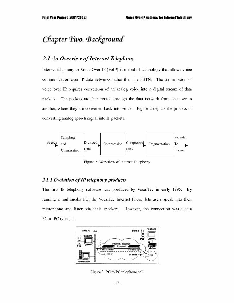
Internet telephony or Voice Over IP (VoIP) is a kind of technology that allows voice
communication over IP data networks rather than the PSTN. The transmission of
voice over IP requires conversion of an analog voice into a digital stream of data
packets. The packets are then routed through the data network from one user to
another, where they are converted back into voice. Figure 2 depicts the process of
converting analog speech signal into IP packets.
Figure 2. Workflow of Internet Telephony
2.1.1 Evolution of IP telephony products
The first IP telephony software was produced by VocalTec in early 1995. By
running a multimedia PC, the VocalTec Internet Phone lets users speak into their
microphone and listen via their speakers. However, the connection was just a
PC-to-PC type [1].
Figure 3. PC to PC telephone call
Sampling
and
Quantization
Speech
Compression
Fragmentation Digitized
Data
Compressed
Data
Packets
To
Internet

Final Year Project (2001/2002) Voice Over IP gateway for Internet Telephony
- 18 -
The next step in VoIP evolution was a gateway. In March of 1996, VocalTec
announced it was working with an Intel Company (Dialogic Corporation) to produce
the first IP telephony gateway. Gateways are the key to bringing IP telephony into
the mainstream. By bridging the traditional circuit-switched telephony world with
the Internet, gateways offer the advantages of Internet Phone to the most common,
cheapest, most mobile, and easiest-to-use terminal in the world.
2.1.2 How does Gateway work?
Conceptually, an Internet telephone gateway (shown in Fig.4) works as follows. On
one side, the gateway connects to the telephone world. On the other side, the
gateway connects to the Internet world (See Fig. 4). The gateway takes the standard
telephone signal, digitizes it, significantly compresses it, packetizes it for the Internet
using Internet Protocol (IP), and routes it to a destination.
Figure 4. Function of Internet Telephony Gateway
A number of configurations can be built from this basic operation. Phone-to-PC or
PC-to-phone operation (Fig. 5a) can take place with one gateway. A Phone-to-phone
operation (Fig. 5b) can occur with two gateways. In order to offer an international
long distance service using gateways, for example, an organization or service provider
can host one gateway in each country. The configuration costs is significantly less
than a traditional circuit-switched service.

Final Year Project (2001/2002) Voice Over IP gateway for Internet Telephony
- 19 -
Figure 5a. Phone-to-PC or PC-to-Phone operation
Figure 5b. Phone-to-phone operation
2.1.3 Standardization
2.1.3.1 H.323
Since there are many different IP telephony products, standards are necessary in the
world of IP telephony. One of the most important areas for standardization is the
protocol between IP telephony products. This standard is based on International
Telecommunications Union (ITU) Recommendation H.323 which covers several
“standard” audio coders such as G.723 for IP telephony [13]. An H.323 network,
with its functional entities, is shown in Figure 6.
Figure 6. An VoIP solution with using H.323

Final Year Project (2001/2002) Voice Over IP gateway for Internet Telephony
- 20 -
The H.323 terminal is an end-user device also known as an H.323 client. It provides
real-time two-way voice, video or data communication with another H.323 terminal.
The client could be a multimedia PC, an IP phone or a terminal adapter that connects
an analog phone or fax machine to the H.323 network. The gatekeeper provides
address translation and call control services to H.323 endpoints. It is also
responsible for bandwidth control, authentication, authorization and accounting. The
gateway in an H.323 network performs the conversion between analog and digital
data. It can also operate as a Multipoint Control Unit (MCU). MCU supports
multi-conferencing between three or more terminals or gateway. MCU is in fact a
conference server with centralized signaling [1].
2.1.3.2 RSVP
The phone network was designed to guarantee a high quality of service even at high
rates of utilization. The Internet, in contrast, provides only best-effort service. The
Internet service can be significantly degraded at high utilization because of the great
delay time. The Internet Engineering Task Force (IETF), together with Internet
backbone equipment providers, is addressing this with technologies like Resource
Reservation Protocol (RSVP), which will let the bandwidth be reserved [11]. RSVP
is a relatively new protocol developed to enable the Internet to support QoS. Using
RSVP, a VoIP application can reserve resources along a route from source to
destination. RSVP-enabled routers will then schedule and prioritize packets to fulfill
the QoS. However, the Internet Phone system of this project will not use RSVP.
As the system is mainly designed for those businesses with their own intranet, there is
a large bandwidth reserved. Moreover, RSVP is only useful when routers are
RSVP-enabled. Unfortunately, most of routers nowadays do not support RSVP yet.

Final Year Project (2001/2002) Voice Over IP gateway for Internet Telephony
- 21 -
2.2 Current Internet Telephony System in market
Nowadays, there are many different Internet Telephony products on the market. In
this section, one of the products is used as an example to illustrate the characteristics
and shortcomings of the existing products in the market.
2.3.1 The Net2Phone
The Net2Phone is one of the most prevalent commercial Internet telephone operators
in the UK. It enables people to place low-cost, high-quality calls from their
computer, telephone, or fax machine to any telephones or fax machines in the world.
Figure 9. The User Interface of Net2Phone
Net2Phone is a free software that can be downloaded from the homepage of
Net2Phone. It supports PC-to-Phone Calls and PC-to-PC calls. Charges only apply

Final Year Project (2001/2002) Voice Over IP gateway for Internet Telephony
- 22 -
to PC-to-Phone calls. These charges accrue on a per minute basis, at rates
substantially lower than telephonic communications.
Other features of Net2Phone include:
I. The Active Contact List
The Active Contact List enables users to see when their friends and family are online
(at their computers) and ready for a call using Net2Phone. It displays another
Net2Phone users’ online/offline status. It is also allowed user to organize the list by
category and call someone with a click of a mouse!
II. Instant Messaging
Net2Phone allows users to send text messages instantly.
Limitation of the product:
Net2Phone provides the basic service for a user to make voice communication.
However, the most significant limitation of Net2Phone is that it needs installation.
Although Net2Phone can be downloaded on the website, it is necessary to install the
Net2Phone program beforehand. Therefore, it limits the places where it can be used.
In addition, it is not free of charge.

Final Year Project (2001/2002) Voice Over IP gateway for Internet Telephony
- 23 -
2.3 Past Research Products
Since this year project is a follow up project, the characteristic of the previous project
is presented in this section.
2.2.1 An IP Gateway for Internet Telephony (2000/2001)
The aim of 2000/2001 Final Year Project was to implement a web-based Internet
Phone system that can make communication between the telephony devices
(telephones and mobiles) and personal computers (PCs). Users use the telephony
devices to dial a particular telephone number; the Internet Protocol gateway detects
the call and receives the call by the modem. After the user has entered the Internet
Protocol Address of remote hosts, the IP gateway allows communication between the
telephone device and a remote PC.
Figure 7. User interface graph of 00/01 project

Final Year Project (2001/2002) Voice Over IP gateway for Internet Telephony
- 24 -
The characteristics of this system are shown below:
1. Programming Language
C++ and Visual Basic were the main programming languages for development. All
communication programs and functions were written in C++ and Visual Basic was
still used for the user interface of the system. Servlet was used to connect the
database system for validation and retrieving the user’s information. Text files were
used as the database system in this project. The structure of the database is shown in
Appendix A.
Servlet is a Java platform technology for extending and enhancing web servers.
Servlet provides a component-based, platform-independent method for building
web-based applications. The main reason for using servlet is that for each request to
a servlet, a lightweight thread is spawned to handle that request. This dramatically
improves the performance of servlet over CGI scripts for the application. [15]

Final Year Project (2001/2002) Voice Over IP gateway for Internet Telephony
- 25 -
2. System Flow
Figure 8. The System flow of web site of 2000/2001 Final Year Project
Figure 8 shows the system flow of the system developed in the 2000/2001 Final Year
Project. When a user starts to use the Web-based Internet Phone system, the
Welcome Page is loaded. If the user is a new user of the system, he/she will need to
register at the New User page. Before using the system, the user should login to the
system with his/her user name and password on the Login Main Page. After login
success fully, the user chooses to a particular service. The users must go to different
pages for different purposes.
3. Features of the System
i. Accept and reject the calls
Before making the voice communication, the caller side sends a request to the listener.
The listener accepts or rejects the call. If the listener accepts the call, the voice

Final Year Project (2001/2002) Voice Over IP gateway for Internet Telephony
- 26 -
communication is established. If the listener rejects, the voice communication is not
established.
ii. User online notice
The users could find out other on-line users by looking at the contact list in the
system.
iii. Phone to PC
The system allowed communication between a telephone device and a PC through a
modem.

Final Year Project (2001/2002) Voice Over IP gateway for Internet Telephony
- 27 -
CChhaapptteerr TThhrreeee.. RReevviieeww ooff RReellaatteedd TTeecchhnnoollooggyy
Before starting to develop the whole system, the following points must be considered.
The first point is how to connect the telephone and the Internet Protocol Gateway. A
Dialogic card is used as a media between a telephone and a computer. In order to let
the gateway automatically handle the telephone call, it is important to know how to
control the dialogic card. In this project, Windows® Telephony Applications
Programming Interface (TAPI) is used to control the dialogic card (see Chapter 3.1 &
3.2).
The size of the voice information affects the transmission times. Larger transmission
time introduces longer delay. Therefore, an encoding and decoding mechanism is
necessary to reduce the size of the voice data (see Chapter 3.3).
Communication of this Internet Phone system is built by the exchange of packets
between the end-points. On the sending side, through using the Internet Protocol,
the voice information is fragmented and encapsulated into packets. Each packet is
then sent to the destination. On the receiver side, the packets are received and
assembled to the original voice information for playback. In this project, the
Window Socket Application Programming Interface (simply know as “WinSock” API)
is chosen to establish the communication (see Chapter 3.4).
During communication, the system needs to record, play back, send and receive voice
data at the same time. Therefore, “Multithreading” technology should be used to

Final Year Project (2001/2002) Voice Over IP gateway for Internet Telephony
- 28 -
make the system perform all the tasks simultaneously (see Chapter 3.5).
Finally, since this Internet Phone System is a web-based system, a method is needed
to embed the system into a web browser. In this case, “ActiveX” with “Dynamic
Link Library (DLL)” is one of the choices (see Chapter 3.6 & 3.7).

Final Year Project (2001/2002) Voice Over IP gateway for Internet Telephony
- 29 -
3.1 Intel® Dialogic® boards
Intel® Dialogic® boards are an industry-standard voice processing boards. These
boards are ideal for applications that require high-performance voice processing.
The model of the board used in this project is D21/H which is a high-performance
digital signal processing (DSP)-based voice processing board with a two-port analog
telephone interface on board.
The D/21H board uses a digital signal processing (DSP technology, making it ideal for
small- and medium-sized, server-based computer telephony (CT) systems -
particularly under the Windows operating systems. Windows support includes TAPI
and WAVE APIs, which facilitate call control, recording, and playback of voice
messages under the Microsoft Windows Open Services Architecture (WOSA). The
D/21H voice processing board gives Windows 95 and Windows NT application
developers a platform for creating sophisticated interactive voice response (IVR)
applications. The D/21H board also supports MS-DOS, OS/2, and UNIX operating
system environments [12].
International Caller ID is also supported on D/21H boards, letting an application such
as IVR receives calling party information via a telephone trunk line. However,
Caller ID is supported only for North America (CLASS protocol), the United
Kingdom (CLI protocol), and in Japan (CLIP protocol) [12].
3.1.1 Limitation of D21/H boards:
During the development of the project, some limitations of the voice processing board
were discovered. These shortcomings affect the performance of the Internet

Final Year Project (2001/2002) Voice Over IP gateway for Internet Telephony
- 30 -
Telephony system.
1. Half duplex
The D21/H board is a half duplex board, which means that users cannot talk and listen
to the other party at the same time. In order to simulate the full duplex functionality,
the Internet telephony System executes either the playback or the recording of other
party’s voice data in the VoIP gateway machine.
2. Sampling frequency and bits per sample
The D21/H board can only support 8000Hz sampling frequency and 8 bits per sample.
Therefore, it not only limits the flexibility of the Internet Telephony system, but also
affects the quality of the voice.
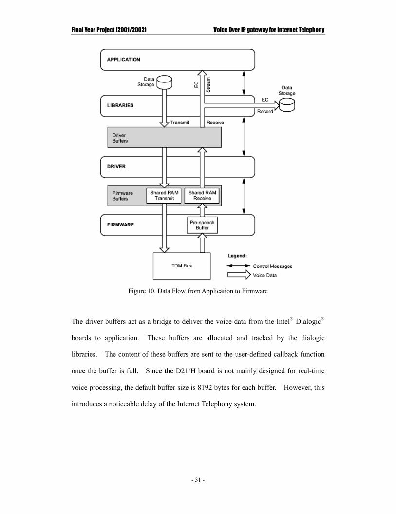
3. Driver buffer size
Figure 10 depicts how data are flowed within difference layers in the Dialogic
software.
Final Year Project (2001/2002) Voice Over IP gateway for Internet Telephony
- 31 -
Figure 10. Data Flow from Application to Firmware
The driver buffers act as a bridge to deliver the voice data from the Intel® Dialogic®
boards to application. These buffers are allocated and tracked by the dialogic
libraries. The content of these buffers are sent to the user-defined callback function
once the buffer is full. Since the D21/H board is not mainly designed for real-time
voice processing, the default buffer size is 8192 bytes for each buffer. However, this
introduces a noticeable delay of the Internet Telephony system.

Final Year Project (2001/2002) Voice Over IP gateway for Internet Telephony
- 32 -
3.2 TAPI
Windows® Telephony Applications Programming Interface (TAPI) is based on the
principles of the Windows Open System Architecture. It lets developers create
telephony applications. TAPI is an open industry standard, defined with
considerable and ongoing input from the worldwide telephony and computing
community [14]. Its main purpose, however, is to provide connections between
Telephony Service Providers(TSPs) and TAPI applications. Applications are
programmed using TAPI. TSPs implement the Telephony Service Provider
Interface(TSPI) functions that are used by the TAPI implementation. Each TSP then
uses whatever interface is appropriate to control its telephony hardware. Figure 11
shows the TAPI architecture.
Figure 11. TAPI architecture

Final Year Project (2001/2002) Voice Over IP gateway for Internet Telephony
- 33 -
The relationship between different components is shown below:
�� An application loads the TAPI DLL into its process space and uses TAPI to
communicate.
�� TAPI establishes an RPC link communications with the TAPI Server.
�� In addition, TAPI creates an MSP object and communicates with it using a
defined set of commands, the Media Service Provider Interface (MSPI).
�� When an application calls a TAPI operation, the TAPI dynamic-link library
validates and marshals the parameters, then forwards the information to
TAPISRV.
�� TAPISRV tracks communications resources available to the local machine and
interfaces with the Telephony Service Providers (TSPs) using the Telephony
Service Provider Interface (TSPI).
�� Communications between a TSP and an MSP take place using a virtual
connection that passes through the TAPI DLL and TAPISRV.
�� The TSP/MSP pair supplies information on device state and capabilities and
implements the specific commands required for a desired response.
This layered approach makes it possible for an application to be developed without
the developers having to worry about the specific hardware provided on a particular
machine. Any telephony hardware vendor can then implement the appropriate parts
of the TSPI without worrying about what telephony applications have been installed.
This separation makes applications and hardware independent of each other.
Therefore, applications and hardware can come and go without directly affecting each
other.

Final Year Project (2001/2002) Voice Over IP gateway for Internet Telephony
- 34 -
3.2.1 TAPI 2 Vs TAPI 3
The newest version of TAPI is 3.0. The major difference between version 2 and 3 is
that TAPI Version 2 is C-based API but Version 3 is a Component Object Model
(COM)-based API. Generally, TAPI 3 is an evolution of the TAPI 2 API to the COM
model, allowing TAPI applications to be written in any language, such as C/C++ or
Microsoft® Visual Basic®.
Figure 12. Windows 2000 TAPI architecture
The left side of the Fig. 12 shows the components shipping today in TAPI 2.x. The
right side shows the new components that are part of TAPI 3.0. The TAPI 3.0 COM
API allows object-oriented, language-neutral software development. It is built on
top of the TAPI server. The C API (to the left) provides call functionality. The new
TAPI 3.0 COM API provides not only call functionality but also media access,
directory access, and terminal access as well [14].
Reasons for choosing TAPI
In fact, there are two methods to control the Dialogic card, TAPI and Dialogic API.
However, TAPI, instead of Dialogic API, is used because:
��TAPI is open standard for telephony applications.

Final Year Project (2001/2002) Voice Over IP gateway for Internet Telephony
- 35 -
��Applications and telephony devices do not depend on each other if TAPI is used.
This can make the system more flexible.
However, TAPI 2 is used because Dialogic TSP does not support TAPI 3.

Final Year Project (2001/2002) Voice Over IP gateway for Internet Telephony
- 36 -
3.3 Voice coders
An efficient voice encoding and decoding mechanism is vital for using the
packet-switched technology. The purpose of a voice coder, also referred to as a
codec (coding/decoding), is to transform and compress analog speech signals into
digital data.
Three widely used compression algorithms have been used in this project:
�� GSM (Group Speciale mobile) – a voice compression algorithm that is just
suitable for speech delivery only.
�� LPC (Linear Predictive Coding) – a linear prediction method such that the
analysis enjoys a number of desirable features in the estimation of speech
parameters as spectrum, format frequencies, pitch and other vocal tract measures.
The quality of voice using this compression algorithm is the worst compared to
the other two compression methods.�
�� ADPCM (Adaptive Differential Pulse Code Modulation Algorithm) – a
variable-bit-rate coding algorithm with the capacity of bit-dropping outside the
encoder and decoder blocks. This compression method provides the best
quality.
All the codecs in this project can convert any audio data to the RTP payload format.
Therefore, the users simply add the RTP header to the payload for RTP transports.
Codecs Class Payload Type
Encoding Type Bit Rate (kbps)
GSM / RPE-LTP GSM_Codec 3 Frame-based 13.2 LPC LPC_Codec 7 Frame-based 5.6
G.711 / PCM alaw PCMA_Codec 8 Sample-based 64
Table 1. The implemented codecs and the corresponding classes

Final Year Project (2001/2002) Voice Over IP gateway for Internet Telephony
- 37 -
3.4 Windows Sockets
The Windows Sockets is one of the most important components of Internet Phone
System. It acts like a bridge to connect two or more hosts in the Internet together.
Through the Windows Sockets, the compressed voice data can be transmitted to other
hosts on the Internet. The following section describes the Windows Sockets and
presents its architecture.
3.4.1 An Overview of Windows Sockets
The Windows Sockets specification defines a network programming interface for
Microsoft Windows which is based on the "socket" paradigm popularized in the
Berkeley Software Distribution (BSD) from the University of California at Berkeley.
It encompasses both familiar Berkeley socket style routines and a set of
Windows-specific extensions designed to allow the programmer to take advantage of
the message-driven nature of Windows.
The Windows Sockets Specification is intended to provide a single API to which
application developers can program and multiple network software vendors can
conform. The advantage of industry wide support for a single API is that
applications can be easily ported from one operation system to another.
3.4.2 WinSock and OSI model
In the International Organization for the Standardization Open Systems
Interconnection (ISO/OSI) model, Windows Sockets, also called Winsock, operates at
the session layer interface to the transport layer. Winsock is an interface between
applications and the transport protocol and works as a conduit for data I/O. The

Final Year Project (2001/2002) Voice Over IP gateway for Internet Telephony
- 38 -
following figure shows Winsock in relation to other Windows CE communication
protocols within the context of the ISO/OSI model [14].
Figure 13. Relation between WinSock and other communication protocols
Winsock simplifies application development in the upper ISO/OSI layers by handling

Final Year Project (2001/2002) Voice Over IP gateway for Internet Telephony
- 39 -
the details of network data exchange at the lower layers. Winsock provides a
programmable interface between the upper layers, 5-7, and the lower layers, 1-4.
Winsock applications reside in the upper, application, presentation, and session layers.
Winsock application data is packaged and transmitted over a network by the lower,
transport, network, data-link, and physical layers.
3.4.3 WinSock2
The latest version of Microsoft windows sockets is WinSock 2. WinSock 2 follows
the Windows Open System Architecture (WOSA) model; it defines a standard service
provider interface (SPI) between the application programming interface (API), with
its exported functions and the protocol stacks. Figure 14 is a block diagram of
WinSock architecture.
Figure 14. WinSock Architecture
With the Windows Sockets 2 architecture, it is neither necessary nor desirable for
stack vendors to supply their own implementation of WS2_32.dll, since a single
WS2_32.dll must work across all stacks. The WS2_32.dll and compatibility shims
should be viewed in the same way as an operating system component [14].

Final Year Project (2001/2002) Voice Over IP gateway for Internet Telephony
- 40 -
3.4.4 TCP Vs UDP
Transmission Control Protocol (TCP) and User Datagram Protocol (UDP) are
operating in the Transport layer of the OSI model. TCP is a connection-oriented
protocol, and is responsible for the reliable transfer of user traffic between two
computers. Consequently, it uses sequence numbers and acknowledgments to make
certain all traffic is delivered to the destination endpoint. UDP is a connectionless
protocol and does not provide sequencing or acknowledgments.
UDP is the preferred choice in this project as it does not provide reliable transmission
and flow control mechanism which introduce considerable delay into the system.

Final Year Project (2001/2002) Voice Over IP gateway for Internet Telephony
- 41 -
3.5 Multithreading
Traditional programs execute in a serial manner with a single thread of control. A
sequential process has a single flow of control, a sequence of instructions executed by
the process. A process is started by the operating system when an application is
launched. When a process begins executed, it has a single thread of control. A
process with more than one thread of control is called multithreaded program.
A thread is an executable unit that utilizes the CPU. It is a sequential of instructions
that are executed within a process. In multithreaded program, there can be multiple
threads running concurrently within a single address space. Each thread can be
considered to be a virtual processor having its own program counter, stack, and set of
registers [7].
Reason of using Multithreading
Multithreading is an essential technology that should be applied in this project. This
is because Internet Phone System is a real-time continuous application, which needs
to record, playback, deliver, and receive voice data simultaneously. In addition, one
more thread is needed to receive interaction from user. As a result, multithreading
technique must be applied in order to meet the above requirements.

Final Year Project (2001/2002) Voice Over IP gateway for Internet Telephony
- 42 -
3.6 ActiveX
ActiveX is based on Object Linking and Embedding (OLE) technologies redefined by
Microsoft® for use on the Internet. OLE can let one application uses the
functionality of another. For example, using OLE, people can insert a Paintbrush
picture into a Word document and have all the Paintbrush functions available inside
the Word document. Therefore, by using ActiveX, web client can use
Internet-enabled applications through a web browser without installation. In other
words, the client web browser is an application within which Internet-enabled
applications are embedded or linked so that the browser can have all the functions
provided by those embedded applications.
3.6.1 ActiveX control
ActiveX controls are Component Object Models (COM). COM is a software
architecture that allows applications to be built from binary software components.
COM is the underlying architecture that forms the foundation for higher-level
software services, such as those provided by OLE, a technology for transferring and
sharing information among applications [14].
Reusing instead of rewriting code saves development effort. ActiveX controls are
reusable software components that can quickly add specialized functionality to Web
sites, desktop applications, and development tools. ActiveX controls have become
the primary architecture for developing programmable software components for use in
a variety of different containers, ranging from software development tools to user
productivity tools.

Final Year Project (2001/2002) Voice Over IP gateway for Internet Telephony
- 43 -
A key advantage of ActiveX controls is that ActiveX controls can also be used in
applications written in many programming languages.
ActiveX is strictly browser dependent. ActiveX controls are only supported by
Internet Explorer 3.0 and higher. More importantly, there are security risks inherent
in ActiveX controls. ActiveX security rests in the “Authenticode” system which is a
scheme for identifying the developers of ActiveX controls. Security is therefore
based on trust. Users need to adjust Internet Explorer Security Level to low in order
to run ActiveX control.
3.6.1.1 Internet Explorer Security Levels
Microsoft® Internet Explorer has three security levels: Low, Medium, and High.
When the user attempts to display a page containing an ActiveX control that does not
guarantee safe initialization or scripting, Internet Explorer does one of the following
based on the current security level.
Security Level Internet Explorer notification
Low No warnings. Controls can be initialized or scripted regardless of data source or scripts.
Medium User is warned of potential safety violation prior to loading the page. User can accept or reject initialization or scripting. If user disables scripting, scripting errors occur when user views the page and attempts to execute the script.
High User is warned of potential safety violation prior to loading the page. User cannot accept or reject initialization or scripting. Scripting errors occur if user attempts to view page and execute script.
Table 2. Action taken of Internet Explorer corresponding to security level
Final Year Project (2001/2002) Voice Over IP gateway for Internet Telephony
- 44 -
3.7 Dynamic Link Library
A dynamic-link library (DLL) is a library of procedures that applications can link to
and use at run time rather than link to statically at compile time. This means that
DLLs can be updated without updating the application, and many applications can
share a single DLL. Microsoft Windows is itself composed of several DLLs that
contain the procedures all applications use to perform their activities, such as
displaying windows and graphics, managing memory, and so on.
An advantage of using DLL is that DLL can reduce memory and disk space
requirements by sharing a single copy of common code and resources among multiple
applications.
Reason of using DLL
The main reason for using DLL is owing to system performance. Since Internet
Phone system is a real time system. Directly calling window socket provided in
ActiveX controls causes delay because of low response time. As a result, DLL must
be used with ActiveX controls to maintain a fast response time for real-time voice
communication.

Final Year Project (2001/2002) Voice Over IP gateway for Internet Telephony
- 45 -
CChhaapptteerr FFoouurr.. SSyysstteemm DDeessiiggnn
4.1 Architecture of the Internet Phone system
The overall Internet Phone system architecture adopts the typical 3-tier approach
where the graphical user interface located at client tier, the required ActiveX
components and runtime DLLs at the middle tier, and the database at the 3rd tier (see
Fig. 15). The client tier is a web browser that provides access to the system. The
middle tier provides three ActiveX Controls for three different web-based applications:
Internet Phone System, File Transfer System and Online Chat System. It also
provides APIs to access the database. The third tier stores the information of users.
Figure 15. Architecture of overall Internet Phone System
This project focuses on VoIP gateway. The login and registration of overall Internet
Phone system were developed last year. Therefore, those parts are not presented in
this report.
CClliieenntt TTiieerr
MMiiddddllee TTiieerr
File Transfer Internet Phone Online Chat
Web Browser
33rrdd TTiieerr
Database

Final Year Project (2001/2002) Voice Over IP gateway for Internet Telephony
- 46 -
4.2 System workflow
Internet Phone is the core for this system, which provides the voice communication
between users. There are two main flows in the Internet Phone application.
��The workflow of making Phone-to-PC calls
��The workflow of making PC-to-Phone calls
4.2.1 The system workflow of making Phone-to-PC calls
The procedure of making a call from the phone to a computer is stated below (or see
Fig. 16):
1) Use the phone to dial a number which is correlated to the dialogic card.
2) When the VoIP gateway receives a call signal, it automatically receives the call
and plays an instruction to the user about how to key in the callee’s IP address.
3) After the user finished keying in the IP address, the VoIP gateway validates the
format of the IP address. If it is a valid IP address, the gateway then sends a
request signal to this IP address. Otherwise, the gateway plays an error message
to the user and asks the user to enter the IP address again.
4) If the reply is “accept”, conversation will start; If the reply is “reject”,
conversation fails and the call will be dropped.

Final Year Project (2001/2002) Voice Over IP gateway for Internet Telephony
- 47 -
Figure 16. Activity diagram of making PC-to-Phone calls

Final Year Project (2001/2002) Voice Over IP gateway for Internet Telephony
- 48 -
4.2.2 The system workflow of making PC-to-Phone calls
The procedure of making a call from a computer to the phone is stated below (or see
Fig. 17):
1) A user clicks a button in the interface to make a PC-to-Phone call.
2) After the user finished entering the callee’s phone number, the Internet Phone
system sends a request signal with the entered phone number to the VoIP gateway.
3) The VoIP gateway makes a phone call to that phone number. If succeed, the
VoIP gateway sends back an “accept” signal and waits callee to answer the call; If
fail, it sends back a “reject” signal and waits for another request.
4) During waiting callee to answer the call, the caller can drop the call by clicking
the “reject” button.
5) When the callee answers the call, conversation starts.

Final Year Project (2001/2002) Voice Over IP gateway for Internet Telephony
- 49 -
Figure 17a. Activity diagram of making PC-to-Phone calls
Figure 17b. Level 2 activity diagram of waiting a callee to pick up the phone

Final Year Project (2001/2002) Voice Over IP gateway for Internet Telephony
- 50 -
4.2.3 Workflow of sending and receiving data
When communication starts, the workflow of the system can be classify into two
classes; sender and receiver. However, both caller and callee will be the sender and
receiver at the same time.
Sender side:
In the sender side, voice information is first recorded either from the phone or the
microphone. The recorded voice information are stored in a set of buffers. When
one buffer is filled up, the system starts to fill up another buffer. At the same time,
the filled buffer is passed to the encoder to undergo compression. After finished
compression, the compressed data are then sent to the receiver. The following
figures show the activities performed in the sender side.
Figure 18. Activity diagram in sender side
Final Year Project (2001/2002) Voice Over IP gateway for Internet Telephony
- 51 -
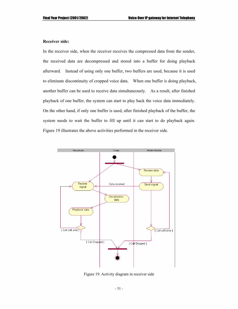
Receiver side:
In the receiver side, when the receiver receives the compressed data from the sender,
the received data are decompressed and stored into a buffer for doing playback
afterward. Instead of using only one buffer, two buffers are used, because it is used
to eliminate discontinuity of cropped voice data. When one buffer is doing playback,
another buffer can be used to receive data simultaneously. As a result, after finished
playback of one buffer, the system can start to play back the voice data immediately.
On the other hand, if only one buffer is used, after finished playback of the buffer, the
system needs to wait the buffer to fill up until it can start to do playback again.
Figure 19 illustrates the above activities performed in the receiver side.
Figure 19. Activity diagram in receiver side

Final Year Project (2001/2002) Voice Over IP gateway for Internet Telephony
- 52 -
CChhaapptteerr FFiivvee.. SSyysstteemm IImmpplleemmeennttaattiioonn
5.1 Problems of Last Year Product and their solutions
Since this Project is further development of the 00/01 Final Year, the first and
foremost thing to do is to make sure that there is no problems in last year’s product.
The problems in the last year product can be classified into three categories: client
side, server side and VoIP gateway.
In client side:
�� Incompatible to Internet Explorer version 6. The last year product is only
supported Internet Explorer version 4 or 5.
�� No change in compression method. Although it allows the user to choose
compression algorithms based on their preference, the system will not use the
chosen compression algorithm to compress the voice.
In server side:
�� No auto installation. The required ActiveX control and DLLs cannot
automatically be downloaded and installed into the client machine.
In VoIP gateway:
�� Poor sound quality. The sound quality of the last year product is very poor.
It is impossible to hear the conversation.
�� Dialing problem. User cannot make call to other user after closing the previous
call. In other words, the system cannot allow a user to make two consecutive
calls.

Final Year Project (2001/2002) Voice Over IP gateway for Internet Telephony
- 53 -
Solution:
Client side problem:
1. Incompatible to Internet Explorer version 6
The problem is owing to validation of the type of browser. Since ActiveX control is
used, it is necessary to check whether the browser is Internet Explorer or not. This is
done by using JavaScript last year. Below shows the function used to valid the
browser last year.
Code 1: JaveScript for checking version of browser last year
From the code, it can be seen that it limits the version of browser to IE4 and IE5 so
the product is not compatible to others version. This restricts users who are using
the latest version: Internet Explorer 6. In other words, it limits the flexibility of the
product. For a good product, the design should be flexible. Therefore, this
problem should be solved in this year product. Code 2 is the new function for
validating the type of browser. The code only rejects those users who are using
Netscape.
Code2: Function for validating browser type

Final Year Project (2001/2002) Voice Over IP gateway for Internet Telephony
- 54 -
2. No change in compression method
One of the strength of this Internet Phone system is that it can allow user to choose the
compression algorithm. However, the compression algorithm does not change even
though users make a change. The main cause is that the user’s choice cannot be
passed into the DLLs.
There are two ways to pass arguments to DLL procedures, by Value or by Reference.
By default, Visual Basic passes all arguments by reference. This means that instead
of passing the actual value of the argument, Visual Basic passes a 32-bit address
where the value is stored. However, many DLL procedures expect an argument to be
passed by value. This means they expect the actual value, instead of its memory
location.
Last year, the chosen compression algorithm is passed to DLL by reference.
However, strings should be passed to APIs using byVal. Visual Basic uses a String
data type known as a BSTR, which is a data type defined by Automation (formerly
called OLE Automation). A BSTR is comprised of a header, which includes
information about the length of the string, and the string itself, which may include
embedded nulls. A BSTR is passed as a pointer, so the DLL procedure is able to
modify the string. (A pointer is a variable that contains the memory location of
another variable, rather than the actual data.) BSTRs are Unicode, which means that
each character takes two bytes. BSTRs typically end with a two-byte null character.
Figure 20. The BSTR type (each box represents two bytes)
Final Year Project (2001/2002) Voice Over IP gateway for Internet Telephony
- 55 -
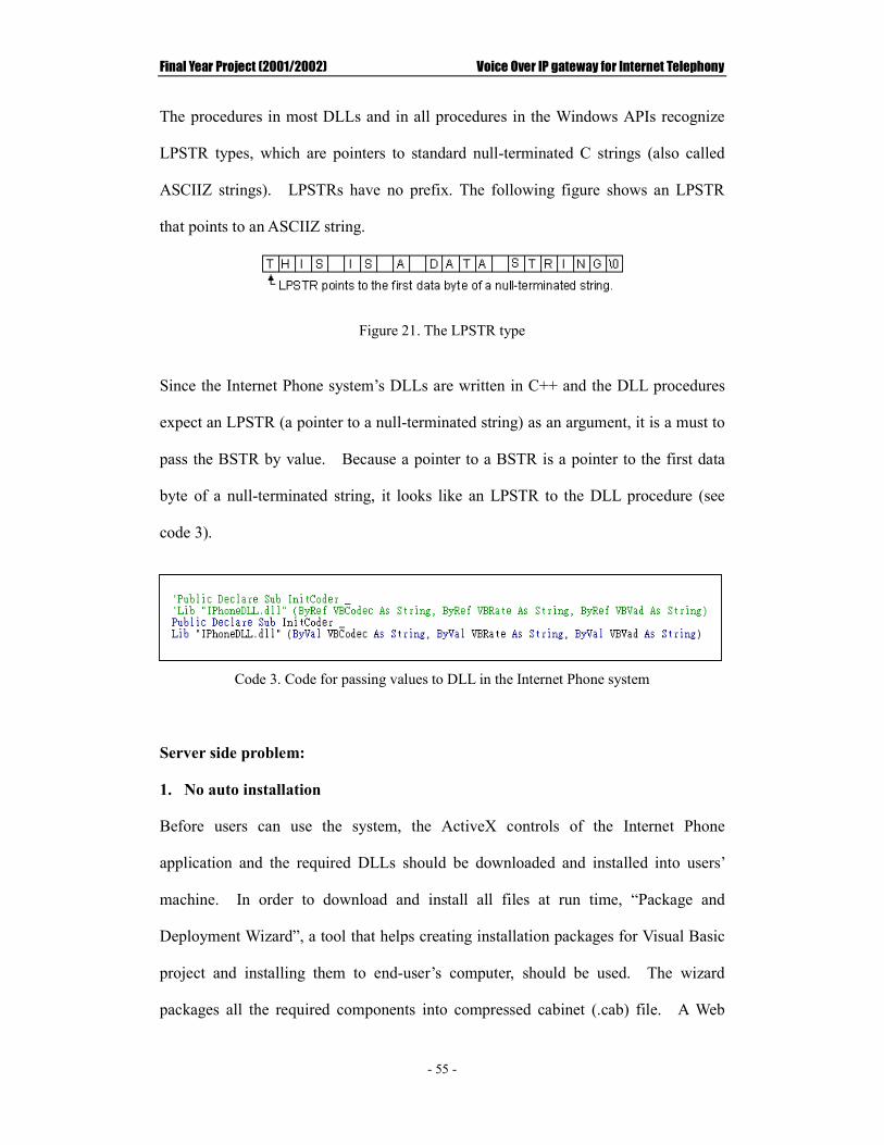
The procedures in most DLLs and in all procedures in the Windows APIs recognize
LPSTR types, which are pointers to standard null-terminated C strings (also called
ASCIIZ strings). LPSTRs have no prefix. The following figure shows an LPSTR
that points to an ASCIIZ string.
Figure 21. The LPSTR type
Since the Internet Phone system’s DLLs are written in C++ and the DLL procedures
expect an LPSTR (a pointer to a null-terminated string) as an argument, it is a must to
pass the BSTR by value. Because a pointer to a BSTR is a pointer to the first data
byte of a null-terminated string, it looks like an LPSTR to the DLL procedure (see
code 3).
Code 3. Code for passing values to DLL in the Internet Phone system
Server side problem:
1. No auto installation
Before users can use the system, the ActiveX controls of the Internet Phone
application and the required DLLs should be downloaded and installed into users’
machine. In order to download and install all files at run time, “Package and
Deployment Wizard”, a tool that helps creating installation packages for Visual Basic
project and installing them to end-user’s computer, should be used. The wizard
packages all the required components into compressed cabinet (.cab) file. A Web

Final Year Project (2001/2002) Voice Over IP gateway for Internet Telephony
- 56 -
page can then be designed for a browser to download the CAB file and install the
required components.
During packaging the component, the wizard prompts an “Included files” window for
including every supporting file that the control needs.
Figure 22. Included File window
By default, the wizard will include some files in system32 directory (highlight in
Figure 22) to support running of the ActiveX control. However, those files already
exist in clients’ computer as it uses Microsoft Windows operation systems. This
means that some files are already running after the operation system starts. As a
result, if a user downloads the CAB file that contains these system files, the
installation process will cause “File sharing violation” problem and then stop the
installation process. That’s why the last year product cannot be automatically
installed into client’s computer. Thus, those system files should not be included as
shown in Figure 22 when creating the CAB file. The Figure below shows all the

Final Year Project (2001/2002) Voice Over IP gateway for Internet Telephony
- 57 -
files that need to be included during packaging. The “IPhone.inf” file, which
contains the information about how to install all the components, will also be
generated into the package.
Figure 23. Package Diagram of Internet Phone application
After finished the whole process, the Package and Deployment Wizard creates two
main sets of files when it packages code for Internet component download:
distribution files and support files. Distribution files are located in the directory
where the wizard begins. This directory typically contains the .cab file and any .htm
files associated with it. The wizard creates a directory for the supporting files and
places the input file (.inf file) in the .cab in this directory. In addition, the support
files directory contains the Diamond Directives (.ddf) file, and other files necessary
for the download.

Final Year Project (2001/2002) Voice Over IP gateway for Internet Telephony
- 58 -
The following table lists all the file types created by the wizard:
Extension Description
.cab Windows setup file or "cabinet" file that contains the .ocx file, the .inf file and other dependent files. This file can be digitally signed to prevent tampering.
.htm HTML file used to display a Web page. This file contains a link to the .cab file and is used to launch the download process.
.ddf Diamond Directives file. This is the project file for creating the .cab files.
.inf Code download information file. This file includes information on how the control should be installed. It permits customization of installation.
.ocx ActiveX control. This file can be digitally signed to prevent tampering.
.dll ActiveX document or code component.
Table 3. File types created by the wizard
Since some DLL files are included, it is essential to put those DLL files into system
directory so that those DLL procedures can be invoked at run time. Otherwise, run
time error will occur because the target DLLs cannot be located. Therefore, after the
package has been created, the .inf file must be modified to customize the installation
process (see Code 4).

Final Year Project (2001/2002) Voice Over IP gateway for Internet Telephony
- 59 -
Code 4. Part of content inside the IPhone.inf file
The parameter “DestDir” (destination of file) of all DLL files should be equal to 11
which means that the file will be located into system directory during installation.
And then the package can be re-created again by using the .ddf file provided.
In order to let the client downloads the created CAB file, some specified HTML
scripts should be included. Code 5 shows the scripts for this purpose.
Code 5. HTML script for embedding CAB file
[IPhone.ocx] file-win32-x86=thiscab RegisterServer=yes clsid={6D32A565-C3FB-429F-BB7F-0F48CA59ECE3} DestDir= FileVersion=1,0,0,1 [IPhoneDLL.dll] file-win32-x86=thiscab RegisterServer=no DestDir=11 FileVersion=0,0,0,0 [Coder.dll] file-win32-x86=thiscab RegisterServer=no DestDir=11 FileVersion=0,0,0,0

Final Year Project (2001/2002) Voice Over IP gateway for Internet Telephony
- 60 -
A HTML tag <OBJECT>, which is used to define the ActiveX control object.
There are some attributes for this tag. ID defines the name of the ActiveX Control.
CLASSID is identifier of the ActiveX Control. CODEBASE specifies the location of
the cabinet file for downloading. Version defines version number for the ActiveX
control. Param defines which parameters are passed to the ActiveX Control. For
example, in the above script, a parameter “_HTMLCodecType” with value gsm is
passed into the ActiveX Control.
In order to get the value of the parameter, the UserControl for ActiveX document
provides an event called “ReadProperties”. In this event, it retrieves the control
instance’s property values from the in-memory copy of the .frm file belonging to the
form where the ActiveX control located. That means, the parameters declared in the
HTML document, which holds the ActiveX Control, can be passed into the ActiveX
control.
By using the function “ProgBag.ReadProperty( )”, the parameter value from the
HTML can be retrieved. Code 6 demonstrates how to retrieve the parameter value
from the HTML.
Code 6. Code for retrieving the parameter value
The first parameter for the function “ProgBag.ReadProperty( )” is used to specify the
parameter name of the retrieving value and the second parameter is used as default
value which will return back if the function fails. The return value for this function
is the value of parameter specified in the HTML document.

Final Year Project (2001/2002) Voice Over IP gateway for Internet Telephony
- 61 -
VoIP Gateway problem:
In order to integrate those useful components into the new system, it is necessary to
use those components correctly and also to make sure there is no problem in those
components.
1. Poor sound quality
The poor sound quality of the last year product mainly accounts for misuse of codec
components and logical error during playback.
I) Misuse of codec components
The voice data are compressed before being sent to receiver side. The compression
is done by function “CompressSndBuf( )”. This function takes two parameters.
The first parameter is a pointer pointed to a buffer that wants to be compressed and
the second one is the size of input buffer. Last year, only half of a buffer is passed to
the compression routine and then sent to receiver so that half of voice data are lost
(see Code 7).
Code 7. Code for calling the compression function last year
The buffer size used last year was 1024 bytes but only 512 bytes data were
compressed and sent to the receiver. The reasonable solution is to compress the

Final Year Project (2001/2002) Voice Over IP gateway for Internet Telephony
- 62 -
whole buffer (see Code 8).
Code 8. Code for calling compression function in the new system
The variable “dwWAudionBufSize” is equal to buffer size which can be retrieved by
calling “GetBufferLength( )”.

Final Year Project (2001/2002) Voice Over IP gateway for Internet Telephony
- 63 -
II) Logical error during playback Last year, the number of bits per sample was 16 (see Code 9 and 10).
Code 9. Code for playback last year
Code 10. Code for defining wave out format last year
Final Year Project (2001/2002) Voice Over IP gateway for Internet Telephony
- 64 -
Therefore, after decompression, each sample is contained in a buffer “recvbuffer”
with a short data type. However, during playback, type casting is performed. A
16 bits short data type is converted into an 8 bits char data type. According to the
MSDN library, when the conversion is from short to char, only low-order byte is
preserved. For example, if the buffer “recvbuffer” contains four short values,
0x11AA, 0x22BB, 0x33CC and 0x44DD, then only 0xAA, 0xBB, 0xCC and 0xDD
are copied to buffer “buffer[i]” and then playback. During playback, the wave out
device reads the data in 16 bits format. This means that 0xAABB and 0xCCDD are
read and played. In this example, it is so obvious that the playback data are totally
different from the original one. That is why the conversation cannot be heard. In
fact, there is no need to perform type casting during memory copy.
2. Dialing problem
The application built last year has problem when a user make a new call immediately
after closing the previous call. According to the last year final report, this problem is
due to the problem of window socket. This is because the socket used in previous
call had not been release immediately after the call is dropped. When the handle to a
socket is closed, additional negotiation occurs between the client and the server. The
server will wait for up to two times of the maximum time that windows used to
receive an acknowledgement from the other end. The dialing problem can be solved
by setting the option SO_REUSEADDR to the socket, which allows the socket to be
bound to an address that is already in use.
However, as User Datagram Protocol (UDP) was used last year, there is no
acknowledgement between the client and the server. The server will not wait any
acknowledgement and it will close the socket immediately. As a result, the dialing

Final Year Project (2001/2002) Voice Over IP gateway for Internet Telephony
- 65 -
problem cannot be solved even by setting the option SO_REUSEADDR.
In fact, the cause of the problem is owing to the problem of multithreading. The
system needs to wait until there are no data to be played. The waiting function
causes one of the threads to terminate when the conversation finishes. So the system
is unable to process another call because it is still waiting data from previous call for
playback. The continuous dialing problem can be solved if that thread is also
terminated when the conversation finished. The detail of the multithreading problem
and its solution is presented in the section 5.2.2, Implementation of Multithreading.

Final Year Project (2001/2002) Voice Over IP gateway for Internet Telephony
- 66 -
5.2 Implementation of VoIP gateway
This VoIP gateway supports two operations, Phone-to-PC calls and PC-to-Phone calls.
The gateway receives and makes the phone call by the dialogic card. Telephony API
is used to control the dialogic card.
Figure 24. Class diagram of the VoIP gateway
Figure 24 shows the classes relationship in the VoIP gateway. The operation of each
class is described below:
CtDialDlg is a class that provides user interface. This class also controls the flow of
the system.

Final Year Project (2001/2002) Voice Over IP gateway for Internet Telephony
- 67 -
CIPhone is a class that consumes the other classes’ functions to provide an interactive
communication with the remote user.
CCoder is a class that performs different compression and decompression algorithms
CWaveAudio is a class that controls wave audio device such as recording and
playback.
CWindowSocket is a class that is responsible for data transmission and reception.
CtCall is a class that represents calls. CtCall provides functions to access TAPI
functions to manipulate the call.
CtLine is a class that represents telephone lines. The main uses of this class is to
open the telephone lines so that telephony event on a line can be handled by the
application.

Final Year Project (2001/2002) Voice Over IP gateway for Internet Telephony
- 68 -
5.2.1 TAPI
The sample project of “Windows Telephony Programming” is used in this gateway.
Class “CtCall” and “CtLine” are provided by this sample project. By using this
project’s library, there is no need to call the TAPI functions directly.
Opening the line
Before making or receiving a call, the application must open a line on which to make
or receive the call. This is done by using the TAPI “lineOpen( )” function. This
function can be accessed through function “Open( )” in class “CtLine( )”.
Code 11. Code for opening the telephone line
Each line is assigned with an object of class “CIPhone” which is used to control wave
audio device and data transmission. Although this approach may not be very useful
in the current gateway, it gives high scalability of the system. This Object Oriented
approach is very useful when the gateway can handle two or more calls

Final Year Project (2001/2002) Voice Over IP gateway for Internet Telephony
- 69 -
simultaneously. For example, by using this approach, each call can have its own set
of buffers to record and play back. And the system does not need to memorize
which buffer should be sent to which remote users. The call’s information is stored
in the object “iphone”. More importantly, since TAPI uses event driven approach,
the object “iphone” is also responsible for distinguishing which call has a particular
event happened. For instance, Call A and Call B both are in process. When call A
is dropped, it is necessary to tell the gateway that the dropping call event is made by
call A so that the gateway can close the connection with call A.
Making a phone call
After the telephone lines are opened, the gateway can start to listen whether there is a
request for making a phone call from a remote user. The VoIP gateway first creates a
thread to receive the remote signaling message and then uses a timer to check the type
of signaling message (see Code 12). There are totally five kinds of signaling
message, as shown in table 4.
Message Type Meaning
ACP Call is accepted. Conversation starts.
REQ Request for a call. If it is PC-to-Phone call, dialed number is also included in this message.
REJ Reject the call request. This signal is sent when the VoIP gateway is busy or the call is rejected by callee.
CLS Close the call. This signal is sent when remote user drops the call during phone in ring.
PLACED Call is placed and the system is waiting callee to pick up the call.
Table 4. Meaning of signaling message

Final Year Project (2001/2002) Voice Over IP gateway for Internet Telephony
- 70 -
Code 12. Code for receiving signaling message
When a request is received, the gateway extracts the phone number to dial from the
signaling message. After that, the gateway can make a call using the TAPI
“lineMakeCall( )” function which is invoked by the function “MakeCall( )” in the
class “CtCall”. Function “MakeCall( )” takes three parameters, phone number to
dial, called country code and object of call back function.

Final Year Project (2001/2002) Voice Over IP gateway for Internet Telephony
- 71 -
However, before the gateway can make the call, it needs to find a telephone line that
is not in use. If all the lines are busy, the gateway will send back a “REJ” signaling
message back to the caller. The function “FindFreeLine( )” is used for finding out a
free telephone line. A negative returned number indicates that all the valid telephone
lines are in progress. The following code shows the procedure of making a phone
call:
Code 13. Code for making a phone call
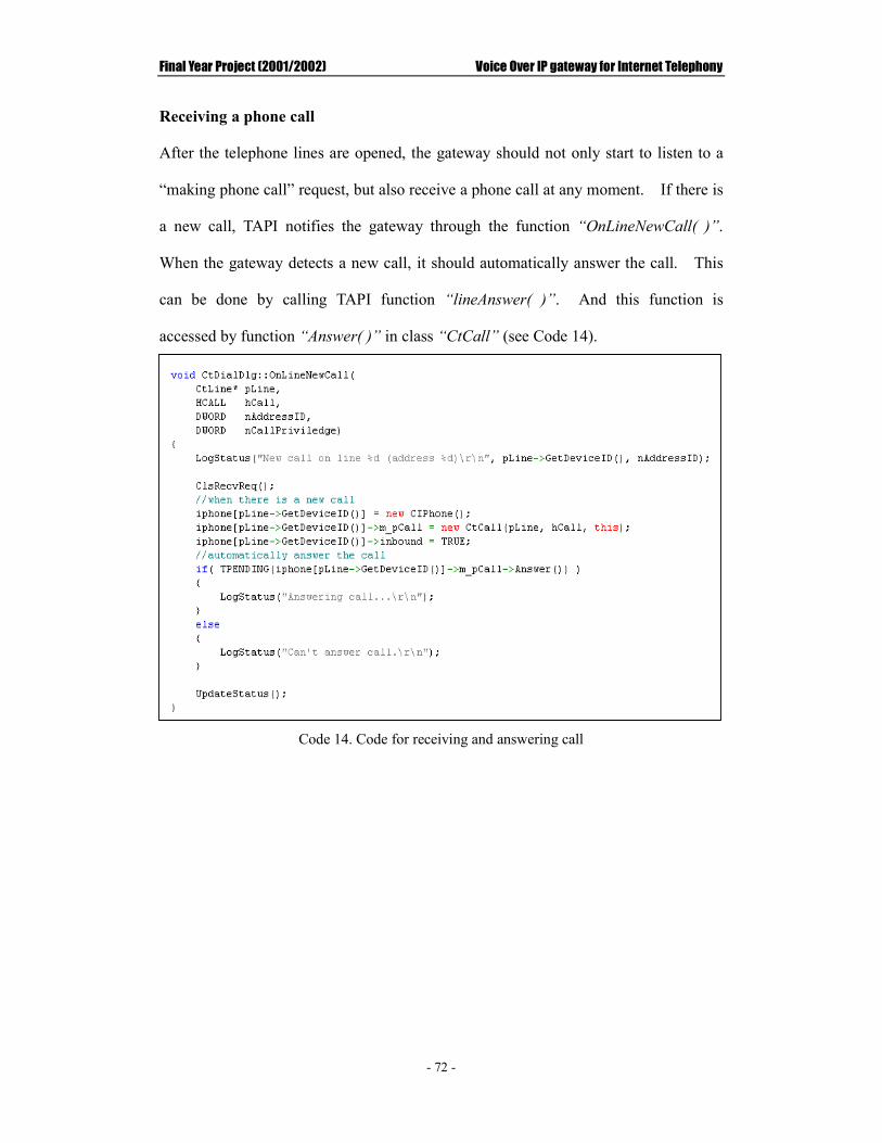
Final Year Project (2001/2002) Voice Over IP gateway for Internet Telephony
- 72 -
Receiving a phone call
After the telephone lines are opened, the gateway should not only start to listen to a
“making phone call” request, but also receive a phone call at any moment. If there is
a new call, TAPI notifies the gateway through the function “OnLineNewCall( )”.
When the gateway detects a new call, it should automatically answer the call. This
can be done by calling TAPI function “lineAnswer( )”. And this function is
accessed by function “Answer( )” in class “CtCall” (see Code 14).
Code 14. Code for receiving and answering call

Final Year Project (2001/2002) Voice Over IP gateway for Internet Telephony
- 73 -
Monitoring Call Progress
TAPI informs the application about the changed call state via the line callback
function and the LINE_CALLSTATE event. The possible states of a call are
enumerated in the LINECALLSTATE_* constants and given in Table 5.
Call State Meaning
LINECALLSTATE_IDLE The call no longer exists.
LINECALLSTATE_OFFERING A new call has arrived.
LINECALLSTATE_ACCEPTED The call has been claimed by an application.
LINECALLSTATE_DIALTONE The switch is ready to receive a number.
LINECALLSTATE_DIALING The switch is receiving dialing information.
LINECALLSTATE_RINGBACK A ring was heard on the call.
LINECALLSTATE_BUSY A busy signal was heard on the call.
LINECALLSTATE_SPECIALINFO An error tone was heard on the call.
LINECALLSTATE_CONNECTED The call has been connected to the other end.
LINECALLSTATE_PROCEEDING Dialing has completed but the call has not yet been connected.
LINECALLSTATE_ONHOLD The call is on hold.
LINECALLSTATE_DISCONNECTED The other end had dropped the call.
LINECALLSTATE_UNKNOWN The TSP cannot determine the current state of the call.
Table 5. Meaning of each call state
By knowing the meaning of call state, the VoIP gateway is able to give different
feedbacks to the user in different state of the call. The state of a call can be received
via the call back function “OnCallState( )”. The call’s state is specified in the
parameter “nCallState” (see Code 15).

Final Year Project (2001/2002) Voice Over IP gateway for Internet Telephony
- 74 -
Code 15. Code for receiving the state of call
Before the gateway can give feedback to the user, it needs to identify the event to
which call. This can be done by calling the function “CheckObject( )”. This
function returns the position of object “iphone” which has a control to the call
“pCall” in the argument list (see Code 16).
Code 16. Code for checking handle of a call

Final Year Project (2001/2002) Voice Over IP gateway for Internet Telephony
- 75 -
Gathering IP address
When the call is connected, the VoIP gateway can give feedback to the user based on
the kind of operations. If it is a PC-to-Phone operation, the gateway can start
recording and playback. However, if it is a Phone-to-PC operation, the gateway
needs to play an instruction to the user instructing him/her about the usage of the
Internet Phone system and guiding the user to key in the callee’s IP address. The
code below shows the action that will be performed when the call is in
LINECALLSTATE_CONNECTED state.
1
Code 17. Code for action performed when the call is connected
The function “MonitorDigits( )” is used to start monitoring the input digits so that
when one of the button on the phone is pressed, the gateway can gather the pressed
button via the call back function “OnCallMonitorDigits( )” (see Code 18).

Final Year Project (2001/2002) Voice Over IP gateway for Internet Telephony
- 76 -
Code 18. Code for gathering input digits
The value of the pressed button is kept in the variable “cDigit”. The value of
“cDigit” will be stored in the variable “ipaddress”. Moreover, when “*” button is
pressed, “ipaddress” will store a dot “.”. This is because the format of IP address is
“XXX.XXX.XXX.XXX”. For instant, if the IP address is “192.168.0.1”, the user
should key in “1”, “9”, “2”, “*”, “1”, “6”, “8”, “*”, “0”, “*”, and “1” in sequence.
After keying in the IP address, the user should press the “#” button on the phone to
start sending the request to the remote user. Before sending out the request, the

Final Year Project (2001/2002) Voice Over IP gateway for Internet Telephony
- 77 -
gateway validates the format of the input IP address. If it is correct, the gateway will
then send out the request to the specified IP address. Otherwise, the gateway will
ask the user to input the callee’s IP address again. The validation of IP address’s
format is done by function “ValidateAddr( )” (see Code 19).
Code 19. Code for validating format of IP address
Dropping the call
When the phone is off hook or the gateway receives “CLS” signaling message while
the phone is ringing, the gateway needs to drop the call. This can be done by the
TAPI function “lineDrop( )”. This function is called when function “Drop( )” in
class “CtCall” is called (see Code 20).
Code 20. Code for dropping the call when signal “CLS” is received

Final Year Project (2001/2002) Voice Over IP gateway for Internet Telephony
- 78 -
Summary of action performed in each state
The table below gives summary for feedback given in each call state.
Call State PC-to-Phone Phone-to-PC
CALLREQUEST_MAKECALL Send back “PLACED” signal to caller.
LINECALLSTATE_CONNECTED Start record and play back. Send “ACP” signal to caller.
Play an instruction to user. Monitor input digits. Send request to callee.Start record and play back if accepted.
LINECALLSTATE_DISCONNECTED Stop record and play back. Drop the call.
Stop record and play back. Drop the call.
LINECALLSTATE_IDLE Release resources Start to handle the next call
Release resources Start to handle the next call
Table 6. Summary of action performed in different call states

Final Year Project (2001/2002) Voice Over IP gateway for Internet Telephony
- 79 -
5.2.2 Multithreading
Multithreading is widely used in the VoIP gateway. There are seven worker threads
in the system. A worker thread is a thread used to do some backend jobs. Each
thread is assigned to a backend process for a particular purpose. Table 7 lists the
purpose of each worker threads.
Worker threads Description
ReqThread Used for receiving PC to Phone Call request
RplThread Used for receiving reply after call request was sent
WaveInThreadProc Used for opening wave audio input device and recording
SocketSend Used for sending recorded data
WaveOutThreadInit Used for initializing the sound output device
WaveOutThreadProc Used for playback
SocketRecv Used for receiving voice data
Table 7. Purpose of each worker thread
Thread “WaveOutThreadProc” is used as an example to illustrate how to apply
multithreading technology in the VoIP gateway.
When a process needs additional threads of control, they have to be created by calling
the WIN32 thread creation API. The function “CreateThread( )” is used to create a
new thread of control in the process. On Success, the function returns a handle to
the newly created thread object. The thread object stores all information about the
newly created thread.

Final Year Project (2001/2002) Voice Over IP gateway for Internet Telephony
- 80 -
Code 21. Code for creating thread
Code 21 shows an example of creating thread “WaveOutThreadProc”. The function
“CreateThread( )” takes six parameters. The first parameter is a pointer to a
SECURITY ATTRIBUTES structure that determines whether the returned handle can
be inherited by child processes. If it is a NULL, the handle cannot be inherited.
The second parameter specifies the initial commit size of the stack, in bytes. If this
value is zero, the created thread uses the same size as the calling thread. The third
parameter is a pointer to the function to be executed by the thread. In this example,
the function “WaveOutThreadProc( )” is executed for playback. The fourth
parameter specifies a single parameter value passed to the thread. The fifth
parameter specifies additional flags that control the creation of the thread. Zero in
this value means that the thread runs immediately after creation. However, at this
time, no other values are supported. And the last parameter is a pointer to a 32-bit
variable that receives the thread identifier.
Final Year Project (2001/2002) Voice Over IP gateway for Internet Telephony
- 81 -
Pitfall of multithreading
Although multithreading can help applications to respond and perform better,
multithread programming will introduce new types of problems. Multithreaded
applications are always more difficult to debug than single-threaded applications.
Since multithreading is a new technology, there is a lack of good debuggers and tools
to help the developers in the development process. Data synchronization problem is
the most critical one. For example, if one thread frees a dynamically allocated buffer,
then when other threads refer to the same buffer, it will cause an access violation.
Since threads can run in parallel and have access to all resources including memory, it
is necessary to synchronize the shared data and to prevent the shared data from
becoming inconsistent.
Data synchronization problem exists in the VoIP gateway. For instance, the system
should wait for the voice data to arrive before the system can start playback. In
order to solve the synchronization problem, the threads use the wait functions of
WIN32 to suspend its own execution until the conditions specified in the wait
function are satisfied. The primary function used for waiting is
“WaitForSingleObject( )”. The function “WaitForSingleObject( )” waits for the
object identified by the first parameter until the object is signaled or the waiting time
specified by the second parameter expires.

Final Year Project (2001/2002) Voice Over IP gateway for Internet Telephony
- 82 -
Code 22. Code for waiting voice data to arrive
The code above is used for doing playback. The system waits for voice data to
arrive before the system can start playback (see Code 22). In the above example, the
system waits for the object “m_hRecv” infinitely. The object “m_hRecv” is signaled
when the system has received the remote voice data. In order to signal an object,
“SetEvent( )” function can be used. The function “ResetEvent( )” is called to set
back the state of the object to non-signaled after the object is signaled. The code
below shows the action that will be performed when the remote voice data are
received.

Final Year Project (2001/2002) Voice Over IP gateway for Internet Telephony
- 83 -
Code 23. Code for receiving remote voice data
When the system has received the data, the system can decompress the received buffer.
The decompressed data are stored in buffer “recvbuffer”. It then signals the object
“m_hRecv” in order to let the system playback the data (see Code 23). When the
conversation finished, the object “m_hRecv” is also signaled for releasing the infinite
waiting in the thread “WaveOutThreadProc” so that wave out audio device can be
closed. Otherwise, the system is incapable to handle another call because of a
deadlock in the thread “WaveOutThreadProc”.

Final Year Project (2001/2002) Voice Over IP gateway for Internet Telephony
- 84 -
5.2.3 Voice compression and decompression
This project makes use of the Speech Codec Library originally provided by my
supervisor, Dr. Mak. This project focuses on how to integrate this Codec Library
into the VoIP gateway. The detail on how to implement the coding and decoding
algorithm is not presented in this report.
Code 24. Code for accessing the Speech Codec Library
Before encoding and decoding start, initialization of variables is needed (see Code 24).
The variable “audio_codec” is an object of the class “Audio_Codec”, a class uses to
perform different compression algorithms. The variable “sendbuffer” and
“recvbuffer” are two independent buffers that contain sent and received data
respectively. The variable “out16buffer” and “outDcpbuffer” are buffers that
contain 16 bits linear PCM audio data. The data type of each buffer is shown below:
Code 25. Code for defining each buffer
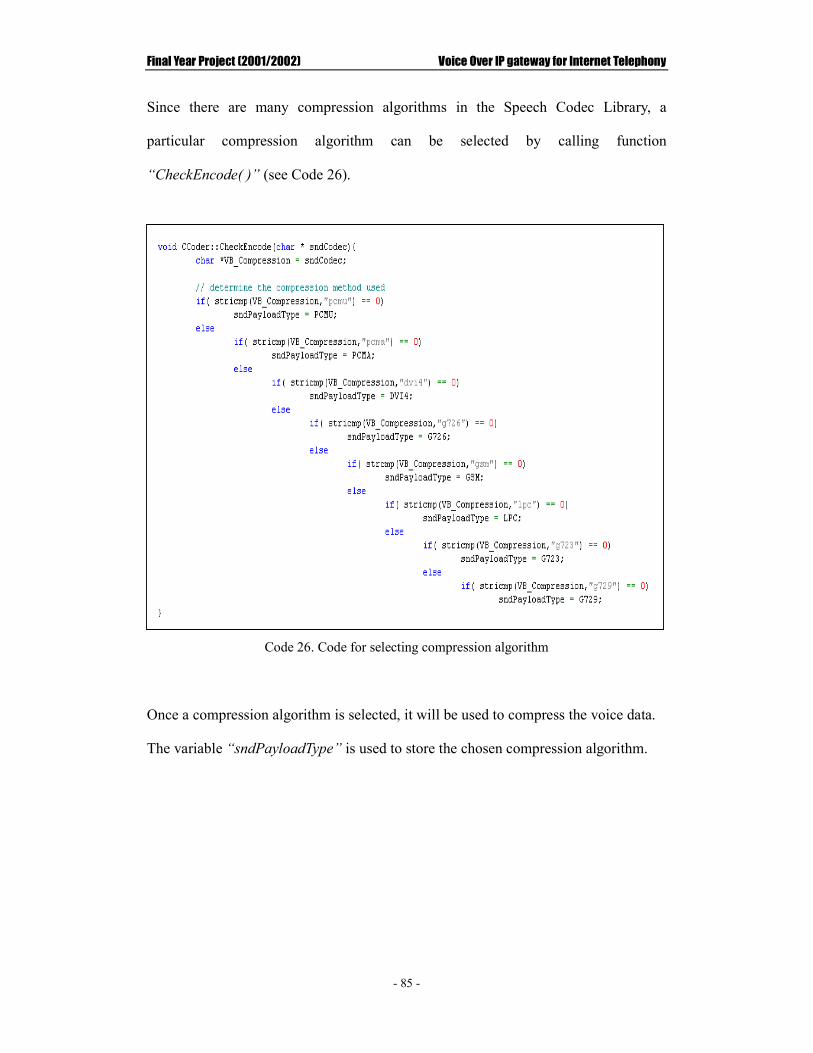
Final Year Project (2001/2002) Voice Over IP gateway for Internet Telephony
- 85 -
Since there are many compression algorithms in the Speech Codec Library, a
particular compression algorithm can be selected by calling function
“CheckEncode( )” (see Code 26).
Code 26. Code for selecting compression algorithm
Once a compression algorithm is selected, it will be used to compress the voice data.
The variable “sndPayloadType” is used to store the chosen compression algorithm.

Final Year Project (2001/2002) Voice Over IP gateway for Internet Telephony
- 86 -
The Dialogic card restricts voice data to 8-bits linear PCM audio format. However,
all codes can handle only 16 bits linear PCM audio. The 8-bits recorded data should
be converted into 16-bits PCM audio format before encoding the data. The function
“linear8PCMtoLinear16PCM( )” is used for this purpose (see Code 27).
Code 27. Code for compressing record data
Since function “linear8PCMtolinear16PCM( )” will allocate new memory to the
buffer “out16buffer”, it is necessary to free the allocated memory back to operating
system when the buffer is not used. Otherwise, memory leakage occurs. WIN32
function “free” is used to free the memory. After the recorded data have been
converted into 16 bits linear PCM audio format, the compression can be started. The
compression is implemented by calling the “Audio_Codec” class function
“encoder( )”, which called the specified encoder (determined by variable
“sndPayloadType”) to undergo compression. The compressed data was stored and
pointed by “sendbuffer”. Unlike the buffer “out16buffer”, the memory used by
“sendbuffer” will not be liberated immediately because the data contained in
“sendbuffer” will be sent out later. Therefore, the allocated memory will be
liberated until there is a new memory assigned to “sendbuffer” again.

Final Year Project (2001/2002) Voice Over IP gateway for Internet Telephony
- 87 -
Similar to compression, decompress can be done by calling the “Audio_Codec” class
function “decoder( )”. After decompression is finished, the function
“linear16PCMtolinear8PCM” is called to convert the data back to 8 bits linear PCM
audio format and then do the playback (see Code 28).
Code 28. Code for decompressing received data
By calling the functions “CompressSndBuf( )” and “DecompressSndBuf( )” in the
class “Coder”, the compression and decompression could be achieved in the system.
The decompression method used depends on the variable “rcvPayloadType”, which is
equal to the compression method of the sending side used. The used compression
method is known during the voice data received. Code 29 shows how to specify the
decompression method after data are received.
Code 29. Code for assigning decompression algorithm

Final Year Project (2001/2002) Voice Over IP gateway for Internet Telephony
- 88 -
5.2.4 Window Socket
This Window Socket library was developed last year. However, there are some
problems in the library including problem of efficiency. As a result, this Window
Socket library is modified in order to integrate it into the whole system. Before
discussing the detail of implementation, it is better to have an overview of how to
establish an UTP connection. Sockets should be created so that the application can
use them to send and receive the data. The figure below illustrates the flow using
UTP to make connection and also the Winsock function involved.
Figure 25. WinSock Function Flow using UDP
Caller socket( )
Create the Socket
bind( ) Give the Socket a Name
sendto( )/recvfrom( ) Send and receive data
closesocket( ) Close the connection
Callee socket( )
Create the Socket
bind( ) Give the Socket a Name
sendto( )/recvfrom( ) Send and receive data
closesocket( ) Close the connection

Final Year Project (2001/2002) Voice Over IP gateway for Internet Telephony
- 89 -
Initializing WinSock2
In order to use those WinSock functions, it is required to initialize WS2_32.dll. The
initialization is done by using the WinSock function “WSAStartup( )”. The
“WSAStartup( )” function must be the first Windows Sockets function called by an
application or DLL. It allows an application or DLL to specify the version of
Windows Sockets required and to retrieve details of the specific Windows Sockets
implementation. In Code 30, the statement “MAKEWORD(2,0)” sets the version of
Windows Socket to 2.0.
Code 30. Code for initiating use of WS2_32.dll
Creating Socket
In sending side:
After initiating the WinSock API, socket can be created. To create a socket, either
receiver’s IP address (for sending data) or local IP address (for receiving data) should
be specified. The local IP address can be retrieved by using the WinSock function,
“gethostname( )” and “gethostbyname( )”. As the IP address is required to be in a
specific data type, in_addr, an Internet address structure for 32-bit Internet Protocol
address in network byte order. A WinSock function, “inet_addr( )”, can be used to
convert the string to this data structure.

Final Year Project (2001/2002) Voice Over IP gateway for Internet Telephony
- 90 -
For data delivery, sending socket can be created by the function
“createSendSocket( )”. Unlike last year project, the function will take three
parameters instead of two. The port number is also passed into the function. Last
year, the same port was used to receive both voice data and signaling messages.
This makes the system complex. Therefore, the new system uses two different ports
to receive different kinds of data to reduce complexity of the system. Code 31
shows the code for creating send socket.
Code 31. Code for creating send socket
In fact, socket is created by the WinSock function “socket( )”. The second
parameter of this function specifies the type of the socket. In this example,
“SOCK_DRAM” is passed to the system, meaning that UDP is used.

Final Year Project (2001/2002) Voice Over IP gateway for Internet Telephony
- 91 -
In receiving side:
Similar to the sending side, the receive socket can be created by calling the function
“createRecvSocket( )”. This function also takes one more parameter – Port number.
However, after the receiving socket has created, it needs to be binded into the system
for use. When a socket is created with a call to the WinSock function “socket( )”, it
exists in a name space (address family), but it does not have any name assigned to it.
Therefore, the WinSock function “bind( )” should be invoked to establish the local
association of the socket by assigning a local name to an unnamed socket. The
following code is the function for creating a receive socket.
Code 32. Code for creating receive socket
Sending and receiving data:
After sockets have been prepared, the system can start to send and receive data. For
sending data, the WinSock function “sendto( )” is used. This function takes six
parameters, including socket used for sending, buffer required for sending, the size of

Final Year Project (2001/2002) Voice Over IP gateway for Internet Telephony
- 92 -
the buffer being sent, indicator specifying the way in which the call is made, the
destination IP address and size of that IP address. On success, “sendto( )” returns
the number of bytes sent. On failure, SOCKET_ERROR is returned. Code 33
shows the code for sending out voice data.
Code 33. Code for sending out voice data

Final Year Project (2001/2002) Voice Over IP gateway for Internet Telephony
- 93 -
Before sending out the data, the data will be packed into the following form:
Figure 26. Format of sending packet
Compression method should be included in the packet so that the receiver can use the
corresponding decompression algorithm to decompress the data. Last year, the
signaling data are also sent out in the above format. However, this is not an efficient
way because it introduces more overheads. The bits for indicating compression
method and size of payload are totally useless for signaling data. Thereby, the
signaling data will be sent out directly. Code for sending signaling data is shown
below:
Code 34. Code for sending signaling data
Compression method
Size of payload Payload (Compressed voice data)

Final Year Project (2001/2002) Voice Over IP gateway for Internet Telephony
- 94 -
For receiving data, the WinSock function “recvfrom( )” should be used. The
function “recvfrom( )” returns the number of bytes received if succeeds. There are
also two functions to receive different kinds of data (see Code 35).
Code 35. Code for receiving data

Final Year Project (2001/2002) Voice Over IP gateway for Internet Telephony
- 95 -
Closing connection
When the sending and receiving processes are finished, the sending socket and
receiving socket should be closed. Otherwise, the resource would be used up. This
step can be done by calling the WinSock function “closesocket( )”, which was used to
close the existing socket. The “WSACleanup( )” function must also be called, which
causs the local machine deregistering itself from a Windows Sockets implementation
and allowing the implementation to free any resources allocated on behalf of the
application or DLL (see Code 36).
Code 36. Code for ending window socket

Final Year Project (2001/2002) Voice Over IP gateway for Internet Telephony
- 96 -
5.2.5 Integration of various technologies
This section gives an example of how the previous technologies can be used together
to perform real-time streaming and data delivery. First of all, before recording is
started, the system needs to initialize WinSock and Coder. This can be done via the
function “initObject( )” provided by the class “CIPhone”.
Code 37. Code for initializing winsock and coder
After initialization, the system can record and deliver the voice data. This can be
done by using the function “OnStartRecord( )” in the class “CIPhone”. This
function uses multithreading techniques to create the thread “WaveInThreadProc” for
recording (see code 38).

Final Year Project (2001/2002) Voice Over IP gateway for Internet Telephony
- 97 -
Code 38. Code of function “OnStartRecord( )”
In the thread “WaveInThreadProc”, the first thing needs to be done is to initialize
parameters for opening the wave input device. This can be done by calling the
function “SetParameter( )” in class “CWaveAudio”. This function takes six
parameters: size of buffers for storing recorded data, number of buffer used, number
of channel to record, sampling rate and bits per sample. After that, the function
“OpenWaveInAudio( )” in class “CWaveAudio” is called to open the wave input
device. This function either takes three or two parameter. If the opening device is
the Dialogic Card, the system passes three parameters. The first one is the device ID,
the second one is the callback function which will be executed when the buffer is full
and the last one is the user defined object to be passed to the callback function
whenever it is called. If the wave input device is opened successfully, the system
needs to prepare a wave-in-header for those buffers that use to store recorded data.
The function “PrepareWaveInHeader( )” in class “CWaveAudio” is used for this
purpose. At this moment, it is necessary to create a socket using the function
“CreateSendSocket( )” to deliver the recorded data. And also the thread
“SocketSend” should be created for data delivery. Finally, the system can start to

Final Year Project (2001/2002) Voice Over IP gateway for Internet Telephony
- 98 -
record. To record, the function “StartRecording( )” in class “CWaveAudio( )” is
called. The code below shows all activities in the thread “WaveInThreadProc”.
Code 39. Code for thread “WaveInThreadProc”

Final Year Project (2001/2002) Voice Over IP gateway for Internet Telephony
- 99 -
When the buffer is full, the wave audio device notices the system via the callback
function specified. In this example, the function “waveInProc” is the callback
function. There are two important steps to perform. First, when the recorded data
arrive, the system compresses the recorded data through the function
“CompressSndBuf( )”. Second, after the data is compressed, the system signals the
thread “SocketSend” to send out the data.
Code 40. Code of callback function waveInProc

Final Year Project (2001/2002) Voice Over IP gateway for Internet Telephony
- 100 -
After the thread “SocketSend” has received an acknowledgment, it can then send out
the compressed data using the function “sendData( )”. After compression, the
compressed data are stored in the variable “sendbuffer” and the length of buffer is
stored in the variable “sendbuflen”. The code below gives code of the thread
“SocketSend”.
Code 41. Code of thread SocketSend

Final Year Project (2001/2002) Voice Over IP gateway for Internet Telephony
- 101 -
5.3 Dynamic Link Library
Dynamic Link Library(DLL) is one of the most important components for Client side
application and also for VoIP Gateway. There are four DLL files in the whole
Internet Phone System: Coder.dll, IPhoneDLL.dll, WaveAudio.dll and
WindowSocket.dll. Table 8 describes the use of each DLL file.
DLL file Description
Coder.dll Use for compression and decompression
IPhoneDLL.dll Provide an interface for ActiveX to invoke the DLL’s functions
WaveAudio.dll Control wave audio device
WindowSocket.dll Implement winsock for data delivery
Table 8. Function of DLL files
In order to invoke the functions in the DLLs, all of the DLL’s functions should be
exported. There are two methods to export DLL’s functions: by
__declspec(dllexport) keyword or by module-definition(.DEF) file. Coder.dll,
WaveAudio.dll and WindowSocket.dll are exported by __declspec(dllexport)
keyword. On the hand, IPhoneDLL.dll is exported by .DEF file. The reason for
doing this is that exporting functions in a .DEF file gives programmer control over
what the export ordinals are. When additional exported functions are added to the
DLL, they can be assigned higher ordinal values (higher than any other exported
function). Therefore, applications using implicit linking do not have to relink with
the new import library that contains the new functions. In other words, there is no
need to rebuild the application if the DLL is modified. This is very important
because the DLL can continue to be enhanced by adding additional functionality
while at the same time ensuring that existing applications will continue to work

Final Year Project (2001/2002) Voice Over IP gateway for Internet Telephony
- 102 -
properly with the new DLL. Since new functionalities are frequently added to the
Internet Phone System, it is better to export the DLL by .DEF file. However,
because Coder.dll, WaveAudio.dll and WindowSocket.dll are used by IPhoneDLL.dll,
there is no need to worry about maintaining a .DEF file and obtaining the decorated
names of the exported functions. Therefore, a more convenient method, by
__declspec(dllexport) keyword, is used.
Export from a DLL Using __declspec(dllexport)
Data, functions, classes, or class member functions can also be exported from a DLL
by using the __declspec(dllexport) keyword. If __declspec(dllexport) is used,
a .DEF file for exports will not be required.
When building a DLL, a header file typically that contains the function prototypes
and/or classes being exported is created, and the __declspec(dllexport) is added to
the declarations in the header file. To make the code more readable, we define a
macro for __declspec(dllexport) and then use the macro with each symbol is being
exported. To export all the public data members and member functions in a class,
the keyword must be putted to the left of the class name as follows:
Code 42. Code for Export from a DLL Using __declspec(dllexport)
Export from a DLL Using .DEF Files
Another way to export functions in DLLs is to use a module-definition file, which is a

Final Year Project (2001/2002) Voice Over IP gateway for Internet Telephony
- 103 -
text file containing one or more module statements that describe various attributes of a
DLL. A minimal .DEF file must contain the following module-definition
statements:
�� The first statement in the file must be the LIBRARY statement. This
statement identifies the .DEF file as belonging to a DLL. The LIBRARY
statement is followed by the name of the DLL. The linker places this name
in the DLL's import library.
�� The EXPORTS statement lists the names and, optionally, the ordinal values of
the functions exported by the DLL. The ordinal values are assigned by
following the function’s name with an at sign (@) and a number. They must
be in the range 1 through N, where N is the number of functions exported by
the DLL.
�� Although not required, typically a .DEF file also contains a DESCRIPTION
statement that describes the purpose of the DLL.
For example, a DLL that contains the code to implement the Internet Phone System
might look like the following:
Figure 27. Example of a module-definition file for IPhoneDLL.dll

Final Year Project (2001/2002) Voice Over IP gateway for Internet Telephony
- 104 -
Since the exported DLL’s functions are consumed by Visual Basis, the function being
exported must be defined as a _stdcall type of function. This keyword is required
for mixed-language programming. The _stdcall keyword takes into account
differences in calling conventions and naming conventions among different
languages.
Code 43. Syntax for exporting C++ function to other languages
Importing DLL’s functions in Visual Basic
In Visual Basis program (ActiveX Control), the DLL’s functions must be declared
before they can be used. These imported functions were declared in the modules
(.bas) in Visual Basic Project. The following code is an example of declaring an
exported DLL’s function “SendReq( )”.
Code 44. Code for declaring exported DLL’s function in VB
From the example, the function, “SendReq( )”, is imported from DLL. The function
is declared as public function, such that it can be called in anywhere within the project.
A keyword Function is used to indicate that the procedure returns a value. Data type
of value returned is specified at the end of the declaration statement. In this example,
a Long value will be returned. If the procedure doesn’t return a value, a keyword
Sub should be used instead of using the keyword Function. The String following
Keyword Lib indicates name of the DLL Name of the DLL or code resource that
contains the declared procedure. Here, the function is imported from PhoneDLL.dll.

Final Year Project (2001/2002) Voice Over IP gateway for Internet Telephony
- 105 -
CChhaapptteerr SSiixx:: CCoonncclluussiioonnss // FFuuttuurree eennhhaanncceemmeenntt
6.1 Achievement summary
�� PC-to-Phone, Phone-to-PC, PC-to-PC calls
The web-based Internet Phone system is capable of providing three kinds of
operations: PC-to-Phone, Phone-to-PC and PC-to-PC. Therefore, users can
make communication between two different computers or between a telephone
and a computer.
�� Good quality of voice
The system is expected to be executed in corporate intranet with a high
bandwidth reserved. Therefore, the testing environment is Fast Ethernet
Network running at 100Mbps. Running at this bit rate, the voice quality is very
good.
�� Availability of choosing Compression algorithms
Three compression algorithms, PCMA, GSM and LPC, are provided for
selection. Users can choose whatever algorithms they want. The default
selection is PCMA because this provides the best sound quality. However, the
network will become busy as more bits will need to be transmitted.
�� Accept and Reject the call
Before communication is established, the caller needs to send a request to the
callee and then waits for acknowledgment. This mechanism provides the callee
with the capability of accepting or rejecting a call. On the other hand, the caller

Final Year Project (2001/2002) Voice Over IP gateway for Internet Telephony
- 106 -
can also have a right to drop the call while waiting for the reply.
�� Instruction provided
An instruction is played to the telephone users to teach them how to key in the
callee’s IP address. Also the format of input IP address will be verified before a
call request is sent out.

Final Year Project (2001/2002) Voice Over IP gateway for Internet Telephony
- 107 -
6.2 Problem encountered during development
6.2.1 Lose voice data problem
In the beginning of development, the buffer size used is 1024 bytes in order to reduce
the delay. However, some data are lost. At the beginning of development,
playback is done on local machine. This means that the lost data is not caused by the
network. Therefore, the playback data are dumped to a file. This file is analyzed
using software called “Cool Edit”, which is used to analyze the wave curve.
Through “Cool Edit”, we discovered that a particular pattern is repeated within a
period. The repeated pattern can be clearly observed when the buffer size increases
to 2048 bytes. A pattern is repeated four times within about one second as shown in
the Figure 28. Therefore, a reasonable step is to increase the buffer size by four
times. When the buffer size it set to 8192 bytes, the lost data problem does not occur.
By checking the information on the Dialogic web site, the default size of the driver
buffer is 8192 bytes. This explains why the lost data problem can be solved when
the size of application buffers are set to 8192 bytes.

Final Year Project (2001/2002) Voice Over IP gateway for Internet Telephony
- 108 -
Figure 28. Outlook of wave shape during playback when the buffer size is 2048 bytes
Reason of lost data problem
For recording, the application needs to prepare some buffers for the wave audio
device to fill in the data. Then the wave audio device randomly chooses one of the
buffers to fill in the data. When the buffer is full, the wave audio device notices the
application via a callback function to indicate which buffer is being used. However,
the dialogic card transfers the recorded data into the application buffers only when the
driver buffer is full. This means that the recorded data are coming in a group of
8192 bytes no matter how large the application buffers are. This data transferring
mechanism makes the time difference between each invocation of callback function
within 8192 bytes to be very small so that the system loses the location of the
previous filled data. This is because the location of recorded data is updated every
time when callback function is executed. The following diagram illustrates the
above argument:
Repeating period is about 1.024s

Final Year Project (2001/2002) Voice Over IP gateway for Internet Telephony
- 109 -
Figure 29. Example of event happened between two 8192 bytes data block arrived
Method to reduce size of driver buffer
In fact, the driver buffer size can be set by using Dialogic API. The
“dx_setchxfercnt( )” function can change the size of the buffer used to transfer voice
data between a user application and the Dialogic hardware. The minimum buffer
size is 1.5KB. And the largest available buffer size is 8K, which is the default.
Time
At this instance, the first 2048 bytes buffer is full. Callback function is executed to update the latest location of recorded data.
At this instance, the second 2048 bytes buffer is full. Callback function is executed to update the latest location of recorded data.
At this instance, the third 2048 bytes buffer is full. Callback function is executed to update the latest location of recorded data.
At this instance, the fourth 2048 bytes buffer is full. Callback function is executed to update the latest location of recorded data.
At this instance, the system copies the latest recorded data for playback. However, the latest used buffer has already been updated to the fourth buffer. The first three buffers’ data are missed for playback. Therefore, the fourth buffer is repeated four times before the next 8192 bytes data arrived.
Next 8192 bytes of data is recorded and copied into the application buffer

Final Year Project (2001/2002) Voice Over IP gateway for Internet Telephony
- 110 -
6.2.2 Discontinuity of sound during playback to telephone user
When a user makes PC-to-Phone call, the callee can listen what the caller says via the
telephone device. However, discontinuity of sound happens during playback to the
telephone user. The possible reason for this is that there is large playback latency for
a dialogic card. Since the sample rate is 8000 samples per second and bits per
sample is 8 bits, time needed to play a 8192 bytes buffer is 1.024 (8192/8000) seconds.
However, the dialogic card takes around 1.100 seconds to play. This means that for
about 70 milliseconds, the system does not playback anything. As a result, it causes
discontinuity between buffers. In fact, this latency also occurs in other sound cards.
However, the latency time of most sound card is about 20 milliseconds, which is not
noticeable to human. In conclusion, the low-level wave API will introduce
playback latency but the playback latency for dialogic card is even larger. The larger
latency time for dialogic card may be due to its two-layer buffering scheme (refer to
chapter 3, overview of a Dialogic card for detail) and bus standard. The D/21H
board must be operated in an ISA slot which is very slow. Typically, the D/21H
board is not used for real-time streaming applications. The D/21H board is better for
applications such as Payment-by-Phone service (PPS).
Suggestions to solving the problem
However, this problem may be solved by using a technology called Microsoft®
DirectSound®. According the MSDN, Microsoft® DirectSound® is the 32-bit
audio application programming interface (API) for Microsoft Windows® 95 and
Windows NT® that replaces the low-level 16-bit wave API introduced in Windows
3.1. It provides device-independent access to audio accelerator hardware, giving an
access to features like real-time mixing of audio streams and control over volume, and
frequency shifting during playback. DirectSound also provides low-latency

Final Year Project (2001/2002) Voice Over IP gateway for Internet Telephony
- 111 -
playback (on the order of 20 milliseconds) so that an application can better
synchronize sounds with other events. DirectSound is available in both the
DirectX™ 2 and the DirectX 3 SDKs.
Different from the low-level wave API, DirectSound only uses single buffer to do
streaming. This buffer is owned by DirectSound, and the application must query the
buffer to determine how much of the wave data has been played and how much space
in the buffer is available to be filled with additional data. Conceptually, this
mechanism is identical to a traditional circular buffer with head and tail pointers.
The following diagrams illustrate the streaming mechanism used with DirectSound
and16 bits wave API:
Figure 30. Single-buffer streaming with DirectSound
Figure 31. Double-buffer Streaming with 16 bits wave API

Final Year Project (2001/2002) Voice Over IP gateway for Internet Telephony
- 112 -
An alternative approach is to use the Dialogic DM3 IPLink board. The DM3 IPLink
platform allows a "voice over IP" call to be connected to the SCbus. By adding
additional SCbus boards, one can build a variety of applications, such as an IP-PSTN
gateway. The DM3 IPLink platform has already integrated with voice compression
technique. Also, networking issue such as H.323 is also included in the IPLink
platform. The following website can provide more information about the IPLink
platform: http://support.dialogic.com/documentation/learnabout/IPLink_tasks.htm

Final Year Project (2001/2002) Voice Over IP gateway for Internet Telephony
- 113 -
6.3 Possible future work
�� Phone-to-Phone operation
Since there is only one gateway in the Internet Phone system, the system cannot
support Phone-to-Phone operation. Thus, one possible future work is to
implement one more gateway to put Phone-to-Phone operation in practice.
�� Voice conferencing
Conferencing is one of the most popular services provided in the traditional
telephony system. In order to replace the traditional telephony system and
compete with the existing Internet Phone products, this VoIP gateway must
provide voice conferencing function.
�� Using Database Management system
The database used in this Internet Phone system is just text file. This may cause
multi-access problems when two users access the database at the same time.
Security problem is another concern. Therefore, database systems such as
MySQL, which is free of charge, can be used to solve the multi-access and
security problems.
�� Personal phone book and contact list
Another advantage of using a database system is that it can handle a large
amount of data and provide personal services such as phone book and contact list
easily.

Final Year Project (2001/2002) Voice Over IP gateway for Internet Telephony
- 114 -
�� Data recovery
Since UDP is used for data delivery, it is possible that some transmitted packets
are lost or arrives out of order. This affects the voice quality. The system will
perform better if there is a data recovery mechanism so that the system can still
have data for playback even though some data are lost or arrived too late.

Final Year Project (2001/2002) Voice Over IP gateway for Internet Telephony
- 115 -
CChhaapptteerr SSeevveenn.. RReeffeerreenncceess
[1] A Vugrinec & S Tomazic, IP telephony from a user perspective, Electrotechnical
Conference, 2000. MELECON 2000. 10th Mediterranean , Volume: 1 , 1998
Page(s): 344 -347 vol.1.
[2] Chris Sells Windows telephony programming: a developer’s guide to TAPI,
Addison Wesley, 1998.
[3] H.M. Deitel & P.J. Deitel, C++ How to program second edition, Prentice Hall,
1998.
[4] Quinn & Bob, WindowsTM Sockets Network Programming, Addison Wesley,
1996.
[5] P. Hui, An IP Gateway for Internet Telephony, The Hong Kong Polytechnic
University, Final Year Report 2000.
[6] Peter Vogel, Visual Basic Object And Component Handbook, Prentice Hall PTR,
2000.
[7] Shashi Prasad, Multithreading Programming Techniques, McGraw-Hill, 1997.
[8] Uyless, B., Voice Over IP, Prentice Hall PTR, 2000, Page(s): 1-30, 138-190.
[9] IP Telephony with TAPI 3.0, Microsoft® corporation
[10] http://support.dialogic.com/releases/winnt/Sr50/PDFFILES/Pgmgd3.pdf, Voice
programming guide of Dialogic API
[11] www.ietf.org, Homepage of the Internet Engineering Task Force
[12] www.intel.com, Homepage of Intel® Corporation
[13] www.itu.ch, Homepage of International Telecommunications Union
[14] www.msdn.microsoft.com, MSDN library
[15] www.vocaltec.com, Homepage of VocalTec Internet Phone

Final Year Project (2001/2002) Voice Over IP gateway for Internet Telephony
- 116 -
CChhaapptteerr EEiigghhtt.. AAppppeennddiixx
Appendix A - Database Structure
This appendix gives the details of database system in this project. In this database,
there are four text files; “database.txt” is about the personal data of the users and the
other three are used to indicate the online statues of the users. (“phonelist.txt” for
Internet Phone, “ftplist” for File Transfer System and “chatlist” for Chat Room).
Database.txt
This database file is used to store the personal data for the users. The table below
shows the structure and usage of the stored data.
Field Description Data Type Last Name User’s Last Name String (Not Null) First Name User’s First Name String (Not Null) Nickname User’s Nickname String (Not Null) Password User’s Specified Password String (Not Null) Phone Number User’s telephone number Integer Email Address User’s Email Address String (Not Null) Address User’s Address String Speech Compression
Compress method used to compress the sending data
String (Not Null)
IP address The IP address used in Internet Phone for establishing connection
String (Not Null)
File transfer port Port number used in File Transfer System
Integer (Not Null)
Chat port Port number used in Online Chat System
Integer (Not Null)
Table 9. Structure of Database.txt

Final Year Project (2001/2002) Voice Over IP gateway for Internet Telephony
- 117 -
Phonelist.txt, Ftplist.txt and Chatlist.txt
In these three database files, there are only two fields in each file; one is “nickname”
and other one is the IP address of using machine.
Field Description Data Type Nickname User’s Nickname String First Name The IP address used in Internet Phone
system String
Table 10. Structure of Phonelist.txt, Ftplist.txt, Chatlist.txt
The main function of these three files is keeping track the status of users. When a
user is using one of the functions provided in the system, the corresponding database
file keeps the nickname of the user and also IP address of PC, which was in use. On
the other hand, when the user leaves the system, the record of the user will be deleted.

Final Year Project (2001/2002) Voice Over IP gateway for Internet Telephony
- 118 -
Appendix B - Resource Requirement
Software and Programming Languages
�� Visual Basis 6.0 – develop client side ActiveX control
�� Visual C++ 6.0 – develop the VoIP gateway and DLL
�� JSDK 2.1 – compile Java Servlet Program
�� Tomcat Server – run Java Servlet Program
�� Dialogic Configuration Manager – activate dialogic card
Hardware
�� At least two computers with full-duplex PCI sound card
�� One dialogic card either connected to PBX or PSTN directly
�� Telephone device
�� Microphone and Speaker
Operation System
�� Windows 2000, NT or 9X provided that WS2_32.DLL ,TAPI32.DLL and
Dialogic TSP must be installed.
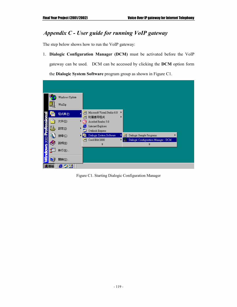
Final Year Project (2001/2002) Voice Over IP gateway for Internet Telephony
- 119 -
Appendix C - User guide for running VoIP gateway
The step below shows how to run the VoIP gateway:
1. Dialogic Configuration Manager (DCM) must be activated before the VoIP
gateway can be used. DCM can be accessed by clicking the DCM option form
the Dialogic System Software program group as shown in Figure C1.
Figure C1. Starting Dialogic Configuration Manager

Final Year Project (2001/2002) Voice Over IP gateway for Internet Telephony
- 120 -
Figure C2. Running of DCM
2. After DCM is run, “start service” button must be clicked to activate the
dialogic board.
Figure C3. Main window of DCM

Final Year Project (2001/2002) Voice Over IP gateway for Internet Telephony
- 121 -
3. After the dialogic board is activated, the VoIP can be compiled and run through Microsoft Visual C++ 6.0.
Figure 35. User Interface of VoIP gateway

Final Year Project (2001/2002) Voice Over IP gateway for Internet Telephony
- 122 -
Appendix D - User manual of Internet Phone System
1. Login to the system
In the login page, you need to enter your user name and password. After finished
entering the user name and password, you can click the keyword [OK] to enter the
Service Page. If you are not a member of the system, you can then click the
keyword Sign it NOW!! to register.
Figure D1. Login page of the Internet PhoneSystem

Final Year Project (2001/2002) Voice Over IP gateway for Internet Telephony
- 123 -
2. Choose Service
After successful login, a Service Page is displayed. You can select one of the
following services; Internet Phone, File Transfer and online Chat room. You can
also modify your information by click the keyword Profit Edit.
Figure D2. Service Page of Internet Phone system

Final Year Project (2001/2002) Voice Over IP gateway for Internet Telephony
- 124 -
3. Internet Phone service
When you choose Internet Phone service, the Internet Phone application is
automatically downloaded and run.
Figure D3. User Interface of Internet Phone application
PC-to-Phone callsPC-to-PC calls

Final Year Project (2001/2002) Voice Over IP gateway for Internet Telephony
- 125 -
Phone-To-PC or PC-to-PC operation
Once the application is executed, it is automatically in waiting states. That means
the system is waiting a call to come. When there is a call request, you can either
accept the call by click button or reject the call by click button. If the
call is accepted, communication starts. Otherwise, the system waits another call
request.
Figure D4. Interface when there is a call request

Final Year Project (2001/2002) Voice Over IP gateway for Internet Telephony
- 126 -
PC-To-Phone operation
When you want to make a PC-to-Phone call, you need to click button on the
main window. After this button is pressed, a keypad is displayed on the right-hand
of the screen. You can then enter the callee’s phone number. If a wrong key is
pressed, you can use button to clear one inputted number. Press button
to dial when finished. You can click button to cancel making the call.
Figure D5. Interface when making a PC-to-Phone call
During waiting the callee to pick up the call, you can drop the call by clicking
button.

Final Year Project (2001/2002) Voice Over IP gateway for Internet Telephony
- 127 -
PC-To-PC operation
When you want to make a PC-to-PC call, you need to choose the receiver in the
contact list first. The contact list indicates who are using the Internet Phone service.
You can update the contact list by clicking button. When you see the callee
appearing in the contact list, you can double-click the callee’s name. And then you
can click button to send out the request.
Figure D6. Interface when making PC-to-PC call
4. Drop call
After communication starts, you can drop the call by clicking button. After
the call is dropped, the system will wait another call request.