Embed Size (px)
Citation preview

The generation of bone-like forms using analytic
functions of a complex variable
Miss EAO Nsugbe and Dr. CJK Williams,
School of Architecture & Civil Engineering, University of Bath, UK.
Abstract
This paper describes the use of analytic functions of a complex variable to generate two dimensional
mappings which can then be used to generate bone-like three dimensional wall forms and arch forms.
1 Introduction
It is open to debate whether one should imitate natural forms in the design of man-made objects for
purely aesthetic reasons. However, if one is so to do, radiolaria (figure 1) and bones (figure 2) have a
particular appeal. Pettigrew(1908), Cook(1903 and 1979) and others have remarked on the persistence of
curvilinear and spiralling formations in plants and animals, insisting that it is proof of design in nature.
Architects and engineers have for centuries been inspired to use natural forms as a source for creativity in
design.
This leads to the question as to how one might design bone-like shapes and produce information for
fabrication using the advanatges of present day computer technology. There are a number of possibilities
which include:
• Sculpture.
• Real physical models using surface tension, threads etc.

• Numerical or analytical models based upon some physical model or law. The physical model may
have the properties of a real-life situation or might be imaginary.
• Purely analytical methods where mathematical functions are chosen to produce the sort of shapes
that are desired.
This paper describes the use of a purely analytic method based upon the use of functions of a complex
variable.
2 Theory
The theory of complex numbers is described in numerous general and specialised mathematics books
(Needham(1997), Spiegel(1964) and Whittaker & Watson(1935)) as well as books in other fields,
particularly fluid mechanics (Lamb(1932)) and heat flow. Here we will describe the particular application
of the theory to the problem in hand.
Consider two complex variables, z = x + iy and w = f + iy where i= -1 and x, y, f and y are real.
The relationship
w = log
za
where a is real means that
z = aew = aef +iy = aef cosy + i siny( )
so that x = aef cosy and y = aef siny .

Figure 3 shows a plots of lines of constant f and constant y obtained from these last two relations. The
origin of x and y co-ordinates is at the centre of the figure. The lines of constant f are circles and the
lines of constant y are radial straight lines.
In terms of heat flow the diagram corresponds to heat flowing away from a source. The heat follows the
direction of the radial lines and the circles are lines of constant temperature, with the temperature
dropping as one moves away from the source.
From this simple beginning more complicated patterns can be generated.
The function
w = log
z + iaa
+ logz - ia
a= log
z2 + a2
a2
corresponds to the flow away from two sources situated at z = ±ia . Figure 4 was produced by
rearranging this equation to give
z = a ew - 1 = a ef cosy + isiny( ) - 1
which enables the lines of constant f and constant y to be drawn.
However, the function
w = log
z + iaa
- logz - ia
a= log
z + iaz - ia
produced figure 5 after rearranging to give
z = ia
ew + 1
ew - 1.
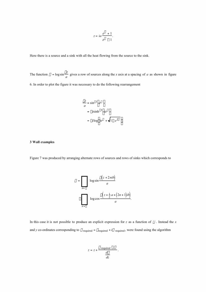
Here there is a source and a sink with all the heat flowing from the source to the sink.
The function w = logsin
pza
gives a row of sources along the x axis at a spacing of a as shown in figure
6. In order to plot the figure it was necessary to do the following rearrangement
pza
= sin-1 ewÊ Ë
ˆ ¯
= -isinh-1 iewÊ Ë
ˆ ¯
= -ilog iew + 1- e2wÊ Ë Á
ˆ ¯ ˜ .
3 Wall examples
Figure 7 was produced by arranging alternate rows of sources and rows of sinks which corresponds to
w = logsinp z + 2nib( )
an= -•
•
Â- logcos
p z + 12
a + 2n + 1( )ib( )a
n=-•
•
 .
In this case it is not possible to produce an explicit expression for z as a function of w . Instead the x
and y co-ordinates corresponding to w required = frequired + iy required , were found using the algorithm
z = z +w required - w
dwdz
.

In order to convert the two dimensional wall-like objects in figure 7 into three dimensions, it is simply
necessary to choose an appropriate function of f for the third co-ordinate.
Figure 8 shows a wall derived from figure 7. In this case the surface is modelled since it is proposed that
the wall is clad with tiles.
Figure 9 was also produced from figure 7. First it was rotated through 90˚, then it was given a third
dimension and then the whole form was distorted. The entire object was thus effectively produced from
three functions of f and y, one for each of the Cartesian co-ordinates.
This means that there is a certain uniformity to the shape and, in theory, every small part of the object
contains enough information on curvature, rate of change of curvature etc. to grow the entire object.
4 Arch examples
Figure 10 was produced by two sources and two sinks and figure 11 was produced by a row of sources
superimposed upon a uniform flow. The lower half of figure 10 was used to generate the cross-sections
and figure 11 was used to generate the long sections of the arch bridge shown in figures 12 and 13. Note
again that every small part of the object contains enough information to grow the entire object.
Figure 14 was produced by the same method, except this time the upper and lower parts do not branch.
However, the incipient branching produces a ‘waist’ in the cross-section. A longitudinal modulation was
also introduced to model individual elements such as castings or bones.
5 A sculpture
The starting point for the sculpture shown in figure 16 was again the pattern of alternating rows of
sources and sinks shown in figure 7. This was mapped into the pattern shown in figure 15 using the
complex function
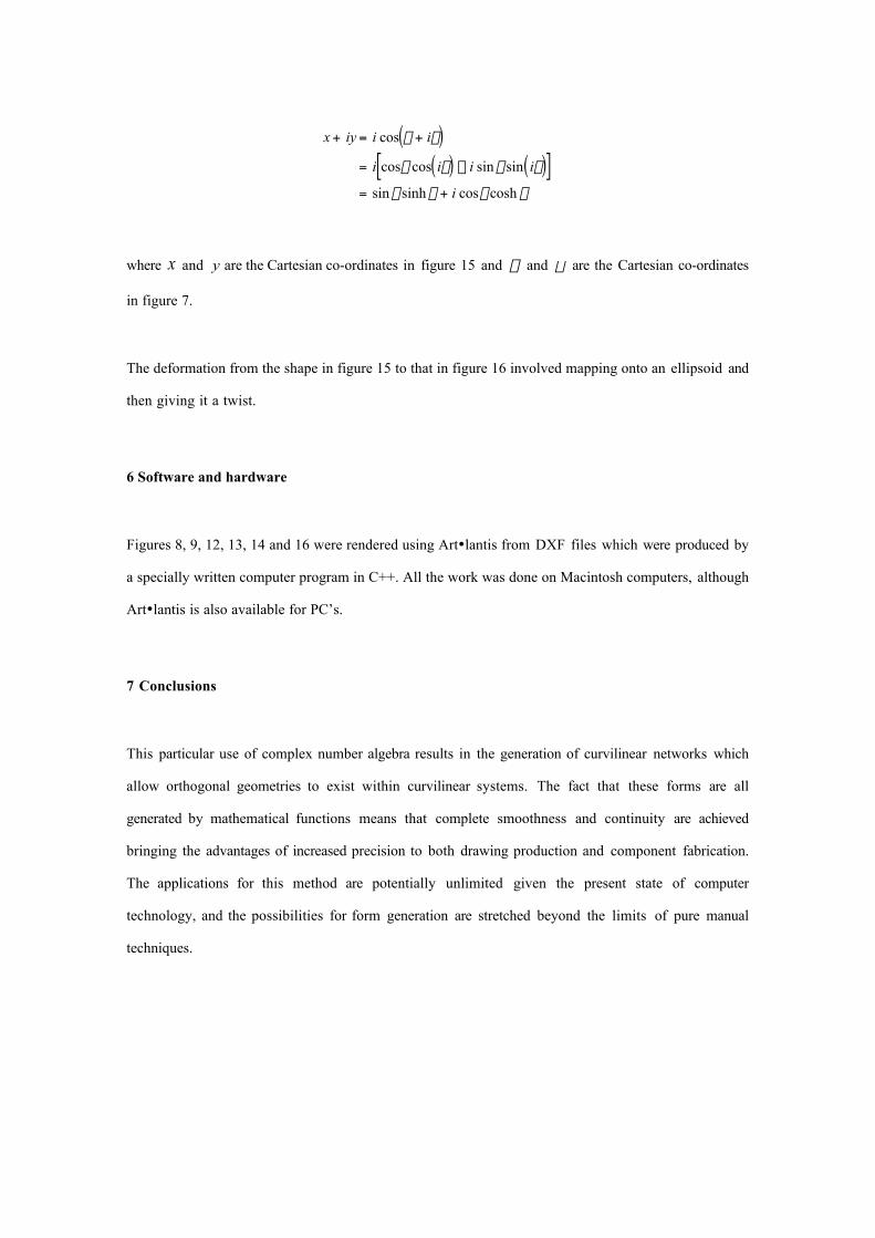
x + iy = i cos x + iV( )= i cosx cos iV( ) - i sin x sin iV( )[ ]= sin x sinh V + i cosx cosh V
where x and y are the Cartesian co-ordinates in figure 15 and x and V are the Cartesian co-ordinates
in figure 7.
The deformation from the shape in figure 15 to that in figure 16 involved mapping onto an ellipsoid and
then giving it a twist.
6 Software and hardware
Figures 8, 9, 12, 13, 14 and 16 were rendered using Art•lantis from DXF files which were produced by
a specially written computer program in C++. All the work was done on Macintosh computers, although
Art•lantis is also available for PC’s.
7 Conclusions
This particular use of complex number algebra results in the generation of curvilinear networks which
allow orthogonal geometries to exist within curvilinear systems. The fact that these forms are all
generated by mathematical functions means that complete smoothness and continuity are achieved
bringing the advantages of increased precision to both drawing production and component fabrication.
The applications for this method are potentially unlimited given the present state of computer
technology, and the possibilities for form generation are stretched beyond the limits of pure manual
techniques.

8 References
Cook, Theodore Andrea, ‘The Curves of Life’, Spirals in Nature and Art based on the Manuscripts
of Leonardo da Vinci, Constable & Co., London 1914 and Dover, New York, 1979.
Cook, Theodore Andrea, ‘Spirals in Nature and Art: a study of spiral formations based on the
Manuscripts of Leonardo da Vinci, John Murray, London 1903.
D’Arcy Thompson, ‘On Growth and Form’, an abridged edition, Bonner, John Tyler (ed.), CUP,
1961.
‘IL3 Biology and Building Part I’, Institute for Lightweight Structures, University of Stuttgart,
1971.
Lamb, H., ‘Hydrodynamics’, sixth edition, Cambridge University Press, 1932.
Needham, T., ‘Visual Complex Analysis’, Clarendon Press, Oxford, 1997.
Spiegel, M. R., ‘Complex Variables with an introduction to Conformal Mapping and its
applications’, Schaum Publishing Co., New York, 1964.
Pettigrew, James Bell, ‘Design in Nature’ Volume I, Longmans, Green & Co. Lon, 1908.
Whittaker, E.T., and Watson, G.N., ‘A Course of Modern Analysis’, Cambridge University
Press, 1935.

Figure 1 Radiolaria Photos: Research Group for Micromorphology, Berlin from IL3(1971)
Figure 2 Bones From Pettigrew, Design in Nature, vol. 1, Longmans, 1908

Figure 3 Single source
Figure 4 Two sources

Figure 5 Source and sink
Figure 6 Row of sources
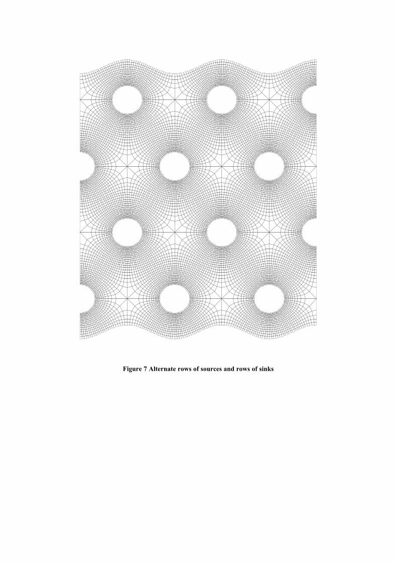
Figure 7 Alternate rows of sources and rows of sinks

Figure 8 Tiled wall
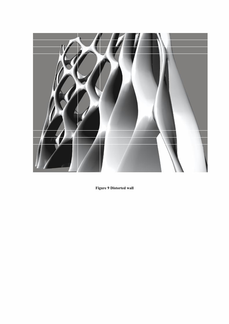
Figure 9 Distorted wall

Figure 10 Two sources and two sinks

Figure 11 A row of sources superimposed upon a uniform flow

Figure 12 Arch bridge
Figure 13 Arch bridge

Figure 14 Bone arch
Figure 15 Sculpture before twisting


Figure 16 Sculpture


![PEP Web - The Analytic Third: Working with Intersubjective ... … · analytic third'. This third subjectivity, the intersubjective analytic third Green's [1975] 'analytic object'),](https://img.dokumen.tips/doc/110x75/6099619e2d4b51336024f694/pep-web-the-analytic-third-working-with-intersubjective-analytic-third.jpg)