Embed Size (px)
Citation preview

INTRODUCTION TO RADIO ASTRONOMY
R. M. j ellming
Radio astronomers measure, analyze, and interpret the radio radiation from
sources outside the atmosphere of the Earth. Most of the radio sources of interest
are outside our solar system.
It is important to emphasize that an astronomer can do no real experimentation.
He is entirely limited to measuring the intensity (and possibly polarization) of
distant radiation sources as a function of frequency, position, and time.
THE RADIO WINDOW
Radio astronomy takes advantage of the "radio window" in our atmosphere.
RFLATIVETRANSPARENCY
X ray- --. 4 Vi ibe
- traviolet ' - ----
: tial ------ Rado •ave- - -- --- ;
Perfectiy wro tirea Mo o h .atutside o rSolp a r syolem.clr Mlul .ono.phri
ah rt l ihl-orptioun Radnio .cin .do n refleaionrOpau
.- . .
. ..•0.0001 0.001 0.01 0.1 10 100 1000: 1 10 1 0 100 1000
Micron Inun Centimeters Meters
WA.%ELENGTH
Fig. 1-I. Elctrormagrnutic .spectrurn showing relative transparency of the earth'strosphere and ionosphere.
The figure shows the relative transparency of the Earth's atmosphere to
radiation of different wavelengths. Until recently we have dealt exclusively with
either the optical window or the radio window. In the last few years infra-red
.astronomy (O.p to 10p) and mm-wave astronomy has grown tremendously. For example,
only a few weeks ago molecular lines of CO and CN were found with the NRAO mm-wave
antenna at Tucson. However, most of radio astronomy still deals with the wavelength
range from two cm to about 20 m.
COORDIOATESBefore going on to more interesting topics, let us pause and give a moments
attention to the problem of specifying the position of a radio source in the sky.
This means choosing a convenient coordinate system.

South Pole
The most important coordinate system is the "equatorial" which is based on
che properties of the Earth's rotation. The above figure defines all the details.
Basically, the equator of the Earth defines a plane and all coordinates are measured
with respect to this plane and the Earth's axis, which is perpendicular to this plane.
The essential definition of these coordinates is based on the definition whereby
every object in the sky is said to return to a particular position every 24 hours.
For this reason, the celestial equator, which is the imaginary projection of the
Earth's equator upon the sky, is divided into 24 hours, with O corresponding to a
particular point in the sky. This Oh point could be chosen arbitrarily, but is
chosen on the basis of the point (one of the two) in the sky where the celestial
equator intersects the plane in which the solar system moves.
Consider any point in the sky. The line to this point will project onto
the equatorial plane. Counting eastward from the Oh point, the amount of the 24
hour scale needed to reach the projection is called the right ascension of the point
in the sky. Since the point will usually not be on the celestial equator, one then
measures, in degrees, the NS angle the point makes with respect to the celestial
equator; this angle is the declination of the point in the sky. In the above figure
object which has a right ascension of 4h and a declination of +300 is indicated.
-rOAv.

-3-
Of course, while the coordinate system -is fixed in the sky, the Earth
:rotates with respect to this coordinate system. .For a particular position on the
Earth at a particular time, the meridian has a right ascension which is called the
sidereal time. In the above figure the observer is at 2 h sidereal time.
At any particular time,, any object in the sky will have a.particular hour
angle, which is the difference between the right ascension of the object and the
sidereal time (right ascension .of the meridian).
As you know, sidereal time is different from the time we normally use,
which is based upon the movements of the Sun. The sidereal day differs from the
solar day by about four minutes. At the autumnal equinox, in the fall, the two
times agree, but thereafter they shift with respect to each other by about 4.
minutes ...a day.
POWER ABSORBED BY A RADIO TELESCOPE..
Let us describe the radiation that comes to us from the sky in terms of an
intensity, I . We define
I.dv dA d dtV
to be the amount of energy in the frequency interval v to v+dv which passes through
an area dA into a solid angle dQ oriented about a particular direction, during the
time interval dt. The units of I are wattsm 2 sterad-Iz-1
4- \ \
We adopt a coordinate system with the z - axis perpendicular to the surface of a radio
-elescope. In this system every point in the sky has coordinates (0,o4).

-4-
Consider an area dA' which is a distance r from the telescope.
is defined by
The solid angle
IS2
dA'rh
A source in the sky occupying a
S , where
S = Sv~s
solid angle s is then said to have a flux density,s
I (0,4)dQ watts m- 2 Hz " .
v (1)
Let us consider radiation in the frequency range v to v+dv incident upon an element
of surface area, dA, of a telescope of area A. The power, incident upon dA from a-
solid angle dS' is given by
dPine = I(0,) cos OdA dQ dv watts.
The total power incident on the telescope is then
Pinc I (0,) cos0 dA dQ dv. (2)
antenna 4ir v

-5-
If I is uniform over the observing band-width, Av,
Pinc =. Iv A I (0,4) cos Od2.
4
(3)
In the special case where I is uniform over.a small source and can be
considered as zero elsewhere, we can use equation (1) to obtain
P Av A cosO Sinc v (4)
For all real antennas, not all of the incident power is absorbed
One can then write
P = 1/2 ilva Ae (0,) I (.,4) d.0
4ir
where the factor 1/2 indicates that typically. only one-polarization is absorbed
and Ae (O,.) describes the absorption properties of the antenna in terms of
an effective area.
Let us define,
A = A (0=0 ,4=0) = effective aperture,e e
thenAe (6,4)
f(0,) = antenna pattern.Ae
In these terms,
Pa = 1/2 Av Ae
4w
(6)
(5)
IIto >f to, ) an

-6-
-Main lobe
For a typical antenna, a cross-section
of the antenna pattern is shown at Ital-poerbeam width (IIPBT
the right.,Ream widthbetw,.n firtnulls (IWIN)
Minor
The following quantities describe various properties of the antenna:
f(0,4)dG = beam solid angle
4wr
MAINLOBE
A... A e
a A
f(O, ) dQ = main beam solid angle
- aperture efficiency
= beam efficiency
4:a A
Ae(0,4 )da =
e f
4-rr 4'tdirectivity.
Sf(e,4 )dQ CA
A further relation which may be derived is
A = X2e A
where A is the observing wavelength. Using this we can re-write equation (6)
as
P = 1/2 Av v(0,4) f (0,4) d.A
4As
(7)

ABSORPTION AND E~ISSION .BY AN ANTENNA
What happens to the power absorbed by an antenna? We will discuss
almost all of the relevant physics in terms of a very simple problem:
the radiation emitted and absorbed by a current element of length Az
carrying a sinusoidal current
I = I eio
where w. 2.v. We will first discuss the case where we supply the current and
the current element emits the radiation. Er
For such a current element one can solve Maxwell's equations for the E and H vectors:
E = (Er,E6,E ), H = (Hr,H ,H )
obtaining
I Az cos .E =
r 2'c c o
+2r
cr
rIr1 eim(t ( - )
IAz sin 1S 4w E 2 + 2- 3
o cr cr r
I Az sin-
4.~ rcrr
eiw(t )e c

E H= H = 0.Sr 0
-1 -2 -3Examining these solutions, we see terms depending. upon "r , r , and r
.-1Obviously,: as r becomes" large, terms involving r -will dominate the solutions.
These terms are called components of the "far field":
i I Az sin ®o
E = " 2 •4w e cr
it -I "Az sin 0H =4 A .cr
iw.(t -e
e.
i (t- )c
e
and all other components are part of the "near field".
astronomical objects at large distances will be in the
Note thatI
E cO 0 0S_
1 . !.
0
z
For obvious reasons, all
far field.
377 ohm
which is: a general result for the far field.
Now let
-2 -1time average energy flux (watts m Hz -)
1 12 Re (E H* E H*)= 2- EoH*
2 09
(I Az sin '0)-- 0
S 2 3 232.s - c r
o
The power passing through an area dA is
.g.

-9-
dP = SdAI Az sin 0) 2 dA
32n c. ro
2 2(I Az sin o) w dS
dP 332 r c"OC
dP 15 3S- -=X
(I Az sin )2O0
f (O, ) =
hence
4'rD
dP/d2
(dP/d )a xmax
2= sin 0
83s
3
32
sin20 i at 0 = 4502
hence HPBW = 900.
The total power emitted by the current element, Pe, is
Now
A = f f > > asp

-10-
dP 1=r')=(Io Az)2 sin.d
15w 22 (Io A.z) dA
40r 2
e 2 o z)
Now all of this has been very simple. We are basically saying that
electrons in an alternating current (with frequency v) element radiate
into space at this frequency with a radiation pattern for which we have
caIcrlated the properties.
The reciprocal statement is also true. Radiation from space with a frequency
v will induce in a current element an alternating current with frequency v.
The receiving antenna pattern (f(O,y)) and its parameters are the same as for
a radiating current element.
This is what happens to the power absorbed by an antenna; if P is the power put
into the electron currents induced in the system
P = P'a e
All useful radio telescopes utilize the same principles. They generally
consist of a dipole current element which is placed at the focal point of a
reflecting surface. A dipole is simply a current element which is optimized for
maximum absorption properties at a particular wavelength.

We can discuss many of the important properties of radio telescope
systems in terms of an electrical circuit in: which the powet
observed by the antenna appears 'as a source of emf.
Antenna
AJJAAAA Receiver
The antenna has an impedance Z= R + iX , and is matched with a receiver witha a a
impedance Z. (including all transmission lines). The receiver has a function
which will be clear in a moment, though we will not discuss many of the details.
In the above circuit the current I is given by
eZ.+z
i a"
and
S= Ra = e R aa a a IZi+Za a
In a properly matched system, the impedances are chosen so that IZ.+ZaI 2 is a1 a
minimum, so the absorbed power is maximized; this occurs when
R. = R.1 a
X = -Xi a
---2e
a 4Ra
Clearly knowing R and measuring e will give a measure of Pa a
We now invoke Nyquist's law:
hence
-11-

.- 12-
In any resistor, the r.m.s. voltage is related to
the temperature of the resistor by
e = 4kTAvR
where Av is the band-width of frequencies propogating
in the resistor.
Hence
P =kT Av (8)a a
where T is called the antenna temperature. This is the basic reason fora
the preoccupation of astronomers with measuring everything in terms of
temperatures.
Let
P = internal noise power when telescope. is not absorbing radiation.
and
T c.orrespornding intern.al temperature.i kAv
When observing
P=P +P. , T=T + T.,a i a 1
but usually
P < < P. and T < < Tia 1 a i
Hence internal noise dominates the power in the system. This means that one
must be very careful when separating a signal from the noise fluctuations of
the system.
Now fluctuations of radio noise in the system are random events.
According to the statistics of random events, n measurements of a randonly fluctuating- 1/2
quantity will typically deviate from the mean by a fraction of the order of n

-13-
The use of a pass-band Av corresponds to taking Av separate measurements
per second. Thus, in a time T, AvT independent measurements are taken and averaged
together. Thus the deviation from the mean (AP, AT) will be given by
P AT -1/2
The time r is the integration time of the receiver.
Without the telescope absorbing power
P.
With the telescope absorbing power,"the signal mixes with the noise.
Clearly, unless
P.a1P>1V
the noise fluctuations will dominate over any signal. It is usual to say
that for reliable detection of a signal one must have
5 P.
P 1
a
or
5 T.T -
In principle, one would like to make Av and t as large as possible, but of course,
there are limitations which we will not go into.

-14-
RELATION BETWEEN OBSERVATIONS AND THE OBSERVED
The starting point for the analysis of any observations is equation (7):
a 2 ,A I())f(O,4)d(7)
where I (.0,) represents all the accessible information about the observable
universe and P is the directly measured quantity. However, before proceeding
any further, let us transform to the temperature domain used in radio astronomy.
.Since (from equation 8)
P = kT Av, (8)a a
we can take T as the primary observable, thena
1 1.
If we then formally transform the intensity to a temperature by defining
Tb = brightness temperature = It,
then
1 •Tb Tb (o, )f(O, )da . (10)
4q
Because the convention is so well established, one must be accustomed to thinking
of intensity in terms of a temperature in the sky.
In principle the observational problem is to obtain maps of T in the sky bya
measuring all points in the sky with the radio telescope. Then one solves for Tb(o,)
using equation (10). In practice things can be very complicated, mainly because (1)
all radiation over angles smaller than the HPBW is smeared together and (2) radiation
from the whole sky reaches the antenna.
-15-
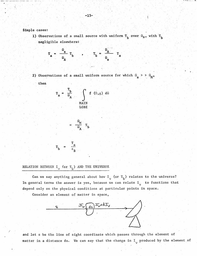
Simple cases:
1) Observations of a small sour
negligible elsewhere:
T = Ta b
A
ice with uniform Tb over Ss, with T b
A TT =. T
b a
2) Observations of a small uniform source for which s > > M,
then
TT = b f (O,) do2a A ..
A
MAINLOBE
%b- S T b
A
TT a
b EB
RELATION BETWEEN. I (or T,) AND THE UNIVERSEV o
Can we say anything general about how Iv (or Tb) relates to the universe?
In general terms the answer is yes, because we can relate I to functions that
depend only on the physical conditions at particular points in space.
Consider an element of matter in space,
and let s be the line of sight coordinate which passes through the element of
matter in a distance ds. We can say that the change in I produced by the element ofv
_ I __ ___

- 16 -
.matter is
dl =emission - absorption.v
Now the emission and absorption properties of matter are well known and can be
V V V
described by. a mass emission coefficient, Jr,and a mass absorption coefficient,. .i,
then, if p. is the 'density in the .element of matter,
dl- = j pds I- K p ds..v •v - v
hence
dl
ds = jvp - K plV V V
If we define
d = pds,v v
where T is the so-called optical depth, thenV
dl'V
dI
JvK ..
K V.v
Now
I dlv V
e dv
t j
+ e - ---V K
V.
T
e
TV v T(e I ) = - e ,.
V KV
ddt

-17-
hence fintegrating from T = .(1)where = I (1) to.V ~ v V S t(2) where I = I (2)
we: get
(1) (2) v1 ) (2) )e e (2
- (2)• - - - I
" (2)
I(2) I (1) ev v
(2)
(1)1 evT 1 .
+
(1)Tv
(2)-[T - T ]
3v
KV
where
S'S
0
K pdsV
If we let
2kTbI:2v 2
and
Jviv
KV
2kTS
and
= 0, thenV (1)v
ivK
V
TVe
dTv
(11)
, zm:NCar., .,. , .dk's

(2)
b Tb ..
: 0
If the source is uniform
(2)
T(2) T (1)b b
(2)and if (2)< < 1
v
while if T (2) >> 1
(2-Tv
+ T 1 -.e
Tb (2)= Tb + T T (2)b b s v
T (2) -Tb s
All that we want to know .about the nature of the universe is tied up in
either
(1) K5 ,j, p or (2) t , Ts.
In general
K'j = f (temperature, density, radiation fields,
collision processes, position, time, etc.)
and it is this list of parameters that affect K and j that we would
like to determine.
Taking equation (11) in a form where S = 0 refers to the "far side
of the Universe" it can be combined with equation (10) to give
(2)'[T
T es
r w
at(12)
(13)

-19-
1a FA
EARTH
jp exp KvPds ds f (0,4) d2 .
4r 0
(14)
This is the basic equation which relates all that we can measure to what we
would like to determine.

ii K .MAR 1971 r