Embed Size (px)
Citation preview

THE FEASIBILITY, RELIABLE COMMUNICATION AND NETWORKINGASPECTS OF PASSIVE WIRELESS SENSOR NETWORKS
A THESIS SUBMITTED TOTHE GRADUATE SCHOOL OF NATURAL AND APPLIED SCIENCES
OFMIDDLE EAST TECHNICAL UNIVERSITY
BY
MEHMET YAGLI
IN PARTIAL FULFILLMENT OF THE REQUIREMENTSFOR
THE DEGREE OF MASTER OF SCIENCEIN
ELECTRICAL AND ELECTRONICS ENGINEERING
SEPTEMBER 2006

Approval of the Graduate School of Natural and Applied Sciences.
Prof. Dr. Canan OzgenDirector
I certify that this thesis satisfies all the requirements as a thesis for the degree ofMaster of Science.
Prof. Dr. Ismet ErkmenHead of Department
This is to certify that we have read this thesis and that in our opinion it is fullyadequate, in scope and quality, as a thesis for the degree of Master of Science.
Asst. Prof. Dr. Ozgur B. AkanCo-Supervisor
Prof. Dr. Buyurman BaykalSupervisor
Examining Committee Members
Prof. Dr. Hasan Guran (METU, EE)
Prof. Dr. Buyurman Baykal (METU, EE)
Asst. Prof. Dr. Cuneyt Bazlamaccı (METU, EE)
Asst. Prof. Dr. Ozgur B. Akan (METU, EE)
Dr. Atilla Ozgit (METU, CENG)

I hereby declare that all information in this document has been obtained andpresented in accordance with academic rules and ethical conduct. I also declarethat, as required by these rules and conduct, I have fully cited and referenced allmaterial and results that are not original to this work.
Name, Last name : Mehmet Yaglı
Signature :
iii

ABSTRACT
THE FEASIBILITY, RELIABLECOMMUNICATION AND NETWORKING
ASPECTS OF PASSIVE WIRELESS SENSORNETWORKS
Yaglı, Mehmet
M.Sc., Department of Electrical and Electronics Engineering
Supervisor: Prof. Dr. Buyurman Baykal
Co-Supervisor: Asst. Prof. Dr. Ozgur B. Akan
September 2006, 46 pages
The primary challenge in wireless sensor network (WSN) deployment is the limited
network lifetime due to the finite-capacity batteries. In accordance with this
challenge, the vast majority of research efforts thus far have focused on the
development of energy-efficient communication and computing mechanisms for
WSNs. In this thesis, a fundamentally different approach and hence completely new
WSN paradigm, i.e., the Passive Wireless Sensor Network (PWSN), is introduced.
The objective of PWSN is to eliminate the limitation on the system lifetime of the
WSNs. In PWSN, power is externally supplied to the sensor network node via
an external RF source. Hence, the lifetime of the system is no longer determined
by the lifetime of the batteries. An alternative communication scheme, modulated
backscattering, is also discussed to be utilized in PWSN. The feasibility of the
proposed system is investigated along with the open research challenges for reliable
iv

communication and networking in PWSN. Additionally, a new medium access
schemee for PWSN, Ultra-Wideband PWSN Medium Access Control (UWB PWSN
MAC), is presented.
Keywords: Wireless Sensor Networks, Modulated Backscattering, Medium Access
Control, Battery-Free Sensor Networks, UWB PWSN MAC
v

OZ
PASIF KABLOSUZ ALGILAYICI AGLARINGERCEKLENEBILIRLIK, GUVENILIR ILETISIM
VE AG KONULARI
Yaglı, Mehmet
Yuksek Lisans, Elektrik ve Elektronik Muhendisligi Bolumu
Tez Yoneticisi: Prof. Dr. Buyurman Baykal
Ortak Tez Yoneticisi: Asst. Prof. Dr. Ozgur B. Akan
Eylul 2006, 46 sayfa
Kablosuz algılayıcı agları (KAA) gelisimde en buyuk zorluk kısıtlı kapasiteye sahip
pillerden kaynaklanan sınırlı ag omrudur. Bu zorlukla beraber, bu zamana kadar
yapılan arastırmaların buyuk cogunlugu KAA icin enerji-etkin haberlesme ve islem
mekanizmaları gelistirmeye odaklanmıstır. Bu tezde, tamamen farklı ve yeni bir
KAA yaklasımı, Pasif Kablosuz Algılayıcı Aglar (PKAA) sunulmaktadır. PKAA’nın
amacı KAA omrundeki sınırlanmayı asmaktır. PKAA’da guc dugumlere dısarıdan
bir RF kaynagı aracılıgıyla iletilmektedir. Dolayısıyla, sistem omru pillerin omru ile
sınırlanmamıstır. Alternatif bir iletisim yontemi, module edilmis yansıtma, PKAA’da
kullanılması amacıyla tartısılmıstır. Onerilen sistemin gerceklestirilebilirligi ile
PKAA icin guvenilir iletisim ve ag yapıları konusundaki arastırma konuları
incelenmistir. Ek olarak, PKAA icin Ultra Genis Band PKAA Ortam Erisim Kontrolu
(UGB PKAA OEK) adlı yeni bir ortam erisim yontemi sunulmustur.
vi

Anahtar Kelimeler: Kablosuz Algılayıcı Aglar, Module Edilmis Geri Yansıtma,
Ortam Erisim Kontrolu, Pilsiz Algılayıcı Aglar, UGB PKAA OEK
vii

ACKNOWLEDGMENTS
The author wishes to express his gratitude to his supervisor Prof. Dr. Buyurman
Baykal and co-supervisor Asst. Prof. Dr. Ozgur B. Akan for their guidance, advice,
criticism, encouragements and insight throughout the research.
This work was supported by The Scientific and Technical Research Council of Turkey
(TUBITAK) under the Grant ]KARIY ER−104E043.
viii

TABLE OF CONTENTS
PLAGIARISM . . . . . . . . . . . . . . . . . . . . . . . . . . . . . . . . . . iii
ABSTRACT . . . . . . . . . . . . . . . . . . . . . . . . . . . . . . . . . . . . iv
OZ . . . . . . . . . . . . . . . . . . . . . . . . . . . . . . . . . . . . . . . . . vi
ACKNOWLEDGMENTS . . . . . . . . . . . . . . . . . . . . . . . . . . . . . viii
TABLE OF CONTENTS . . . . . . . . . . . . . . . . . . . . . . . . . . . . . ix
LIST OF FIGURES . . . . . . . . . . . . . . . . . . . . . . . . . . . . . . . . xi
CHAPTER
1 INTRODUCTION . . . . . . . . . . . . . . . . . . . . . . . . . . . . 1
2 PWSN MODEL AND COMMUNICATION ARCHITECTURE . . . . 4
3 THEORETICAL ANALYSIS OF PWSN . . . . . . . . . . . . . . . . 8
3.1 Power Interception Characteristics of the PWSN Node . . . . . . 11
3.2 Modulated Backscattering for PWSN . . . . . . . . . . . . . . . 14
4 COMMUNICATION IN PWSN . . . . . . . . . . . . . . . . . . . . . 17
4.1 Active Transmission using RF Power . . . . . . . . . . . . . . . 17
4.1.1 Continuous Operation . . . . . . . . . . . . . . . . . . . 17
4.1.2 Discontinuous Operation . . . . . . . . . . . . . . . . . . 18
4.2 Modulated Backscattering as the Communication Technique forPWSN . . . . . . . . . . . . . . . . . . . . . . . . . . . . . . . 18
4.3 Hybrid Methods . . . . . . . . . . . . . . . . . . . . . . . . . . 19
5 PWSN COMMUNICATION PROTOCOL SUITE . . . . . . . . . . . . 20
5.1 Physical Layer . . . . . . . . . . . . . . . . . . . . . . . . . . . 20
5.2 Data Link Layer . . . . . . . . . . . . . . . . . . . . . . . . . . 22
5.2.1 Reservation-Based Protocols . . . . . . . . . . . . . . . . 22
5.2.2 Contention-Based Protocols . . . . . . . . . . . . . . . . 23
ix

5.3 Network Layer . . . . . . . . . . . . . . . . . . . . . . . . . . . 24
5.3.1 Data-centric and Flat-architecture Protocols . . . . . . . . 24
5.3.2 Hierarchical Protocols . . . . . . . . . . . . . . . . . . . 25
5.3.3 Location-based Protocols . . . . . . . . . . . . . . . . . . 25
5.3.4 QoS-based Protocols . . . . . . . . . . . . . . . . . . . . 26
5.4 Transport Layer . . . . . . . . . . . . . . . . . . . . . . . . . . . 27
6 UWB PWSN MAC . . . . . . . . . . . . . . . . . . . . . . . . . . . . 29
6.1 The PWSN MAC Problem . . . . . . . . . . . . . . . . . . . . . 29
6.2 UWB Communication in PWSN . . . . . . . . . . . . . . . . . . 30
6.3 The Joint Physical - MAC Solution Overview . . . . . . . . . . . 31
6.4 The UWB PWSN MAC Protocol . . . . . . . . . . . . . . . . . 34
6.4.1 Pulse Repetition Period Formation . . . . . . . . . . . . . 34
6.4.2 Collision Avoidance . . . . . . . . . . . . . . . . . . . . 35
6.5 The Feasibility and Performance Evaluation of the UWB PWSNMAC . . . . . . . . . . . . . . . . . . . . . . . . . . . . . . . . 36
6.6 Discussions . . . . . . . . . . . . . . . . . . . . . . . . . . . . . 42
7 CONCLUSIONS . . . . . . . . . . . . . . . . . . . . . . . . . . . . . 44
REFERENCES . . . . . . . . . . . . . . . . . . . . . . . . . . . . . . . . . . 44
x

LIST OF FIGURES
2.1 A typical proposed PWSN architecture with passive sensor nodes fed byan RF source. . . . . . . . . . . . . . . . . . . . . . . . . . . . . . . . . 4
2.2 Building blocks of a typical PWSN node. . . . . . . . . . . . . . . . . . 5
2.3 Basic modulated backscattering circuitry. . . . . . . . . . . . . . . . . . 7
3.1 Induced voltage on the antenna for 3 different frequencies with a 4WEIRP source antenna. . . . . . . . . . . . . . . . . . . . . . . . . . . . 10
3.2 Induced voltage on the antenna for 3 different frequencies with a 0.5Wsource and 30dBi antenna. . . . . . . . . . . . . . . . . . . . . . . . . . 11
3.3 Maximum distance for 10mW intercepted power vs. frequency for thenode fed by omnidirectional and directional antennas. . . . . . . . . . . 13
3.4 Maximum communication range by modulated backscattering for thehalf-wave dipole. . . . . . . . . . . . . . . . . . . . . . . . . . . . . . . 15
6.1 An UWB PWSN communication scenario, in which both node A and Bcommunicates with the receiving node. . . . . . . . . . . . . . . . . . . 31
6.2 An example UWB pulse emitted from the RF source. . . . . . . . . . . . 32
6.3 The received pulses at the receiving node. . . . . . . . . . . . . . . . . . 33
6.4 A summary of the proposed protocol. . . . . . . . . . . . . . . . . . . . 37
6.5 An example PWSN topology. . . . . . . . . . . . . . . . . . . . . . . . 38
6.6 Collision simulation results. . . . . . . . . . . . . . . . . . . . . . . . . 39
6.7 Maximum PRP lengths of the link rate simulation. . . . . . . . . . . . . 41
6.8 Maximum PRP lengths of the link rate simulation with attenuation takeninto account. . . . . . . . . . . . . . . . . . . . . . . . . . . . . . . . . 41
xi

CHAPTER 1
INTRODUCTION
Conventional sensor network communication model assumes the deployment of
low-cost, low-power multifunctional sensor nodes [2]. Among all the design
considerations, the power availability is the primary concern which alters WSN design
from conventional wireless network design. Conventional wireless network nodes
either have infinite power or rechargeable batteries, however WSN nodes run on
limited power capacity of their batteries, which cannot be recharged due to dense and
random WSN deployment. The research efforts thus far have sought new methods
to prolong the limited lifetime of the WSN; either by improvements in the physical
layer or by efficient computing and communication techniques [2]. However, the
finite capacity batteries eventually deplete, and the WSN runs out of energy.
Clearly, the reason for limited life span is the batteries with limited capacity.
Following the depletion of its battery, a sensor node is no longer in service.
With the depletion of the batteries of the majority of nodes, the network becomes
nonfunctional. After the batteries of the majority of the nodes are depleted, the
deployed nodes are inoperable, thus redundant in the environment. In conclusion,
a battery powered WSN is a disposable system, the use of which is strictly limited by
the life span of the batteries.
An alternative source of power, particularly a source without limited capacity, should
be considered for WSN. Such a network, i.e., a WSN with unlimited power, is no more
a disposable system, hence, more functional and feasible. External radio frequency
(RF) power, in this regard, stands as a promising source for WSN. The problem to be
investigated here is whether it is practical to remotely feed the sensor nodes with this
new power source.
1

Considering remote feeding with RF power, RFID emerges as a progressing
technology, which is about to be utilized in a number of applications [21]. In passive
RFID tags, the whole system is run on the power from an external RF source. The
RF power incident on the tag is converted to DC power, which in turn, operates the
internal circuitry of the tag. The tag transmits back the information to the source
by modulated backscattering, which is basically modulating the incident RF signal
by passively switching the reflection characteristics of the tag. The switching is also
accomplished by the DC power converted from the incident RF signal. Since no active
transmission is involved, the power consumption for communication is very low on
passive RFID tags. However, the range of these systems are very short (e.g. usually
not exceeding 10m) [11, 21].
The passive RFID tags generally transmit the stored identification information. In
case of a sensor network, on the other hand, the data obtained by the sensors should
de transmitted. The development of wireless, remotely powered telemetry systems
[12, 17], in this regard, is an encouraging progress. In [12], RF power can be stored
on the node, and then can be consumed to run a temperature sensor with a transmitter.
While there are some preliminary studies which aim to integrate RFID with sensor
networks in order to improve the sensing capabilities [3, 11, 18, 20], to the best of our
knowledge, there has been no effort which intends to address the energy limitation
problem of WSN from a fundamentally different approach.
Rather than enhancing the lifetime of the network within the conventional WSN
approach, a completely new sensor networking paradigm, i.e., Passive Wireless
Sensor Networks (PWSN), which is free of battery lifetime constraint, is introduced
in this thesis. The objective of this work is to investigate the potential of eliminating
the lifetime constraint of wireless sensor networks with PWSN and point out the
challenges for efficient and reliable communication in PWSN and related open
research issues to the research community. A WSN without lifetime limitation is
no more a disposable system, hence more functional, cost efficient and feasible. The
system runs as long as power is delivered in, and remains idle but ready to operate
2

when no power is incident on the network.
The rest of the thesis is organized as follows. In Chapter 2, the overview of the PWSN
system model and the communication architecture are introduced. In Chapter 3, the
theoretical background of the analysis on PWSN, related derivations and calculations
are presented. The discussions on alternative communication schemes are presented
in Chapter 4. In Chapter 5, the communication protocol suite for PWSN along with
the open research challenges are discussed. In Chapter 6, a new medium access
scheme for PWSN, Ultra-Wideband PWSN Medium Access Control (UWB PWSN
MAC), is presented. Finally, the thesis is concluded in Section 7.
3

CHAPTER 2
PWSN MODEL AND COMMUNICATIONARCHITECTURE
Unlike conventional WSNs, the sensor network proposed in this study is fed by an
external power source, and is operable as long as power is delivered to the system. In
PWSN, the source of energy, as alternative to the batteries of conventional WSNs, is
an RF power source. A typical deployment scenario of PWSN is shown in Fig. 2.1.
RF Source
Sensor Field
RF Power
Figure 2.1: A typical proposed PWSN architecture with passive sensor nodes fed byan RF source.
4
An RF source, which is assumed to have unlimited power, feeds the PWSN nodes
with RF power. Accordingly, voltage is induced on the receivers of the sensor nodes,
which is converted to DC. The DC power is either used to wake up and operate the
sensor node, or kept in a charge capacitor to be used later. Like conventional WSNs,
the sensor nodes in the system proposed are assumed to be randomly deployed. The
RF source transmits1 RF power to run the sensor network nodes, simultaneously it
transmits and receives information from the PWSN nodes. The RF source antenna
of PWSN should either be omnidirectional or directional. Omnidirectional antennas
assure equal power radiation in all horizontal directions, so that they may feed
PWSN homogenously. Directional antennas, on the other hand, have concentrated
power radiation in certain directions and are appropriate to feed PWSN from distant
locations.
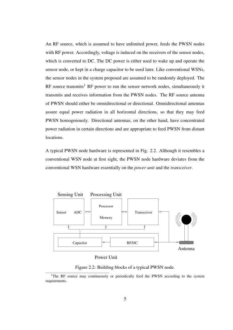
A typical PWSN node hardware is represented in Fig. 2.2. Although it resembles a
conventional WSN node at first sight, the PWSN node hardware deviates from the
conventional WSN hardware essentially on the power unit and the transceiver.
Antenna
Sensor ADC
Capacitor RF/DC
Transceiver
Processor
Memory
Power Unit
Sensing Unit Processing Unit
Figure 2.2: Building blocks of a typical PWSN node.
1The RF source may continuously or periodically feed the PWSN according to the systemrequirements.
5

In a conventional WSN node, the power unit is a battery. An additional unit called
the power generator is sometimes offered as a support device to the power unit. It is
usually a power scavenging device, such as a solar cell, and is not employed as the
sole source of power for the sensor node. In the PWSN node, however, the power
generator, which is an RF-to-DC converter, is an inherent part of the power unit and
is a fundamental device. It is the unique power source of the sensor node. The power
unit delivers the power received from the RF-to-DC converter to the rest of the units
of the sensor node and stores extra power, whenever available.
The transceiver of a conventional WSN node, on the other hand, is typically a
short range RF transceiver. Compared to the other units of the node, the power
consumption of the transceiver is considerably high. For this reason, here, we
consider modulated backscattering [14], a passive and less power consuming method,
as the communication architecture for PWSN. In this architecture, the incident signal
from the RF source is reflected back by the PWSN node. The node modulates this
reflected signal by changing the impedance of its antenna, thereby transmits the data,
that is gathered from its sensing unit and processed by its processing unit, back to the
RF source2 passively.
The transceiver for modulated backscattering is much less power consuming and
less complex, compared to conventional RF transceivers. Although the receiver for
both architectures are quite similar, the transmitter of the modulated backscattering
architecture is basically a switching circuitry for the antenna impedance, as seen
in Fig. 2.3. Furthermore, the maximum communication range of modulated
backscattering is determined by the intensity of the incident signal, and the sensitivity
of the corresponding receiver. Thus, long range communication with the PWSN node
is theoretically achievable without increasing the power consumption of the node,
given a sensitive receiver and a powerful RF source is present.
2The RF source may also operate as the sink in PWSN.
6

Controller
Modulator Switch
AntennaSupply Capacitor
Figure 2.3: Basic modulated backscattering circuitry.
Alternatively, conventional RF transceivers may also be employed in the PWSN
nodes [13], in case sufficient power is available on the node. Hybrid architectures, i.e.,
modulated backscattering hardware and RF transceiver operating cooperatively on the
PWSN node may also be considered. Discussions on the conceivable communication
techniques in PWSN are provided in Section 4.
In our analysis, PWSN nodes are assumed to be equipped with omnidirectional
antennas. The omnidirectional antenna has a nondirectional radiation pattern in the
horizontal plane but a directional radiation pattern in the vertical plane, which makes
it advantageous for the random deployment assumption of PWSN. To be appropriate
for PWSN, the antenna is preferred to be low cost. With these constraints in mind, a
basic omnidirectional and cheap half-wave dipole antenna is considered together with
a high gain omnidirectional antenna.
Within the PWSN model, we perform analysis to investigate the feasibility of PWSN.
The theoretical background, as well as the details and results of the analysis are given
next.
7

CHAPTER 3
THEORETICAL ANALYSIS OF PWSN
In PWSN, the RF signal directed on the node supplies all the required power. Thus,
it is necessary to see whether significant amount of power can be transmitted to the
nodes over reasonable distances. To estimate the power incident on the nodes, the
Friis transmission equation [4] is given by
Pr
Pt= (
λ4πR
)2G0tG0r (3.1)
where Pr is the received signal power, Pt is the power transmitted from the source, G0t
is the gain of the transmitting antenna, G0r is the gain of the receiving antenna, λ is
the wavelength of the signal, and R is the distance between the antennas.
Considering communication by modulated backscattering, we perform analysis to
obtain the maximum ranges, over which a source transmits signals and can extract
the information carried by the reflected signal it receives. The characteristics of
modulated backscattering is observed by the radar equation [4]
Pr =PtGσAe
(4π)2R4 (3.2)
where Pr is the received reflected signal power, Pt is the power transmitted from the
source, G is the gain of the antenna, σ is the radar cross section of the reflector, Ae is
the effective aperture of the receiving antenna and R is the distance from the source to
the reflector. The radar cross section (σ) is a parameter, which is used to characterize
the backscattering properties of an object, when it is target to RF signals. The effective
aperture (Ae) of an antenna is the area, which gives the power delivered to the antenna,
when multiplied by the incident power density on the antenna itself [4].
8

In our analysis of modulated backscattering, we assume the gain of the directional RF
source antenna as 30dBi, and the receiver sensitivity of the RF source as −100dBm .
30dBi is a high gain for a conventional antenna, but it is within reach at an affordable
cost. −100dBm is a typical value of receiver sensitivity. Being commonly used, the
characteristics of the half-wave dipole, are well known [4]. For the λ/2 dipole, the
radiation resistance is 73Ω, maximum directivity is 1.643, and the radar crossection is
approximately 0.86. In this respect, the known radar crossection value makes the half-
wave dipole an appropriate choice for the PWSN nodes in the analysis of modulated
backscattering. As a result, the half-wave dipole antenna is considered as the PWSN
node antenna in modulated backscattering analysis.
In PWSN, RF signals induce voltage on the node’s antenna, and the induced voltage
should be rectified to DC in order to be utilized in the PWSN node. Hence, conversion
of the intercepted power to DC is a significant issue to be investigated. To inspect this
problem, the recently developed efficient RF-DC converters may be employed [12].
In [12], the receiver can convert the RF power to DC as long as 100mV of voltage is
induced on the receiving antenna. Hence, the treshold induced voltage level of 100mV
should be exceeded on the nodes’s antenna, in order that the node may intercept
power. In this regard, the induced voltage on the PWSN antenna is calculated by [4]
Aem =|Vt |
2
8Wi[
1Rr +RL
] (3.3)
where Aem is the effective aperture of the antenna, Vt is the voltage induced, Wi is the
incident power density, Rr is the radiation resistance and RL is the load resistance.
Using (3.3), the relation between the induced voltage and frequency is expressed by
Gλ2
4π=
|Vt |2
8Wi[
1Rr +RL
] (3.4)
As seen from (3.4), the gain of the receiver antenna is a crucial parameter on power
interception characteristics of the PWSN node. The higher antenna gain provides
better power interception capability. As previously discussed, on the other hand,
using omnidirectional antennas on the nodes is preferred. Within these constraints,
a 8.5dBi gain omnidirectional antenna is assumed to be used on PWSN nodes. The
9

the radiation resistance of this antenna is 50Ω. Antennas with these specifications
are available on the market, but the length of these products (i.e around 50cm.) form
drawback for the randomly scattered tiny PWSN nodes. However, these commercial
products are designed for various purposes (i.e marine antennas or outdoor WLAN
antennas) antenna design specifically for PWSN can overcome this disadvantage.
10 20 30 40 50 60 70 80 90 1000
0.1
0.2
0.3
0.4
0.5
0.6
0.7
Distance (m)
Vol
tage
(V)
Induced Voltage on the Antenna vs. Node Distance for 4W EIRP Source
500MHz1GHz2GHz100mV line
Figure 3.1: Induced voltage on the antenna for 3 different frequencies with a 4WEIRP source antenna.
The emitted power from the source is another effective parameter on the observations.
The first constraint is of course the regulations on the Effective Isotropic Irradiated
Power (EIRP). In accordance with this constraint, and directional source antenna
assumption, the 4W maximum EIRP rule of FCC on WLAN for directional antennas
is obeyed. At this point, the applicability of PWSN on military purposes should
be recalled. Monitoring borders or tactically sensitive areas on an irregular basis
can be provided by PWSN. For such purposes, increasing the EIRP level above the
regulations may guarantee the safety of the monitoring troops. In such scenarios, the
10

FCC regulations are most likely to be ignored, and the EIRP level is increased to
keep the soldiers secure. Regarding such situations, the PWSN feasibility analysis is
repeated for 0.5W output power with the 30dBi directional source antenna.
100 200 300 400 500 6000
0.1
0.2
0.3
0.4
0.5
0.6
0.7
Distance (m)
Vol
tage
(V)
Induced Voltage on the Antenna vs. Node Distance for 0.5W Source
500MHz1GHz2GHz100mV line
Figure 3.2: Induced voltage on the antenna for 3 different frequencies with a 0.5Wsource and 30dBi antenna.
The rest of the analysis is performed in two parts: The details of the investigations on
the power interception characteristics are presented in Section 3.1. Then, we discuss
modulated backscattering in PWSN in Section 3.2.
3.1 Power Interception Characteristics of the PWSN Node
In the first analysis, we inspect the conversion of intercepted RF signals to DC. To
see the ranges up to which power may be extracted from the incident signal, i.e. the
100mV treshold may be exceeded on the node’s antenna, the induced voltage on the
antenna versus distance is calculated by (3.3). The initial calculation is made for the
4W EIRP source case and plotted for three different frequencies, which is shown in
11

Fig. 3.1.
The maximum distance to induce 100mV on the node for 4W EIRP at 2GHz is 13m,
this distance increases to 26m at 1GHz and 51m at 500MHz. Decreasing range by
increasing frequency is expected from (3.4). The conclusion of this plot is that it
is possible to transmit operational energy to the PWSN nodes and to meet the RF
emission regulations simultaneously. However, the maximum distance of 26m at
1GHz claims that the source must come close to the PWSN in order to transmit power,
requiring 4W EIRP source to be mobile.
On the other hand, the same inspection of the ranges up to which power may be
extracted from the incident signal is repeated with the high output power, for military
application scenarios. Here, 0.5W output power with the 30dBi directional source
antenna is employed, the corresponding EIRP is 500W . The results are presented in
Fig. 3.2.
It is clear in Fig. 3.2 that 100mV can be induced on the antenna from 142m at 2GHz,
142m at 1GHz and 569m at 500MHz which is a promising result, stating the feasibility
of PWSN at high power military applications, i.e. the troops may feed the PWSN from
distant secure locations, given high RF power is emitted.
Next, we calculate the maximum distance at which a node can intercept 10mW
power. Here, it should be noted that 10mW is an approximate power value to run the
processor and the sensor hardware on a typical sensor network node [9]. We initially
perform analysis using the formula (3.1) for the 4W EIRP source case. The resulting
distance to transmit 10mW power to the PWSN node at 1GHz is 1.27m. This result
is anticipated, since the permitted RF power emission levels are expected to limit the
power transmission range. The results in Fig. 3.1 should here be remembered, and it
should be noted that lower but operational power can be transmitted to the nodes even
at these low power levels. The solution to operate the PWSN node is either to store
the transmitted power or to reduce the power consumption of the PWSN node. These
options will be discussed in the following sections.
12

For the high output power cases, two different RF source antenna assumptions, i.e.,
first an omnidirectional one, which can feed the surrounding nodes simultaneously,
and afterwards a directional antenna are considered. The tradeoff between using an
omnidirectional antenna and a directional antenna will be discussed on the results of
these calculations, which are shown in Fig. 3.3.
0.4 0.6 0.8 1 1.2 1.4 1.6 1.8 2 2.2 2.4
20
40
60
80
100
120
140
160
Frequency (GHz)
Dis
tanc
e (m
)
Maximum Distance for 10mW Intercepted Power
PWSN Node Fed by an Omnidirectional AntennaPWSN Node Fed by a Directional Antenna
Figure 3.3: Maximum distance for 10mW intercepted power vs. frequency for thenode fed by omnidirectional and directional antennas.
The omnidirectional source used in Fig. 3.3 has a gain of 12dBi, which is a
commercially available choice. For the output power level, here, 10W is used,
considering the high emission requirement of power transmission and the safety
requirement of the troops which feed the PWSN. In the figure, we observe that at
1GHz, remote feeding is attainable up to only 8m for an omnidirectional source
antenna, but for the directional source antenna the range rises to 63.5m. The
improvement of range by use of a directive antenna is significant. However, the
directional antenna transmits power only to a small portion of PWSN, where it is
13

aligned to. A solution to this problem might be a mobile or rotating RF source with a
directional antenna. Conversely, a stationary omnidirectional antenna feeds the whole
network topology continuously, although with considerably less power. To get equal
power levels in the sensor field, either an omnidirectional antenna fed by excessive
power or a directional antenna fed at reasonable power levels but having extra power
consumption to provide rotation or mobility should be used. Here, it should be noted
that the detectability of PWSN is significantly higher, if the omnidirectional antenna
is used, due to the constant high power level on the sensor field. Therefore, a moving
or rotating directional antenna appears to be a better solution for PWSN. In any case,
from Fig. 3.3, we may conclude that the power incident on the PWSN nodes are
sufficient for reasonable distances.
The converted DC power in the node may or may not be consumed instantly. If it is
not to be consumed, the storage of power on the node is of interest. If power storage
can be achieved, the PWSN nodes become able to operate, even when the RF source
does not feed them. In this regard, the performance of the ultracapacitors are very
promising [5]. A 3V, 10F ultracapacitor with a time constant of 1.0s weighs only 6.6g.
For an operation range of 1V (between 1.5V and 2.5V ) like in [12], and an average
power consumption of 10mW , a PWSN node with a fully charged ultracapacitor runs
about 30 minutes, although no RF power signal is present. These results claim that
a fully charged PWSN node can operate similar to a conventional WSN node for
reasonable durations. This option will be discussed in detail in Section 4.
Hence, we conclude that, transmission of power through RF signals to the node is
theoretically possible. The distances required to transmit and store power (142m
and 63.5m respectively, at 1GHz) are also promising. This conclusion encouragingly
implies that a sensor node may be fed by an external RF source, can store RF power,
and operate on the RF power rather than batteries.
3.2 Modulated Backscattering for PWSN
The transmitted power from the RF source in PWSN may directly be used by the
nodes to communicate, namely by modulated backscattering [14]. By this method,
14

the power consumption of the nodes may drop drastically. Thus, the required power
level at the nodes decreases and the ranges calculated in Section 3.1 may be improved,
increasing the coverage of PWSN without increasing the total power consumption.
In this regard, the ranges at which modulated backscattering is possible are calculated.
In this case, the source antenna is omnidirectional with 12dBi gain, and the PWSN
node is equipped with a half-wave dipole, as discussed in 2. The results are shown in
Fig. 3.4.
0.4 0.6 0.8 1 1.2 1.4 1.6 1.8 2 2.2 2.4
300
350
400
450
500
550
600
650
700
Frequency (GHz)
Dis
tanc
e (m
)
Maximum Reflection Distance vs. Frequency Graph
Halfwave Dipole
Figure 3.4: Maximum communication range by modulated backscattering for thehalf-wave dipole.
The maximum distance of communication at 1GHZ is around 470m, which makes
the modulated backscattering a practical option for PWSN. Consequently, it is clear
that nodes fed by an external RF source can form an effective PWSN with sufficient
coverage.
The results obtained above prove that passive communication is an advantageous
15

method to be considered for PWSN. A detailed discussion on the possible approaches
for communication in PWSN are presented next.
16

CHAPTER 4
COMMUNICATION IN PWSN
From the results of Section 3, it is evident that PWSN is feasible and achievable. The
communication techniques to be used in PWSN, however, remain to be examined. In
this section, we will first investigate, whether conventional communication schemes,
which employ active transmission, can be adapted to PWSN. Then, modulated
backscattering, as well as hybrid architectures are considered for PWSN.
4.1 Active Transmission using RF Power
As long as sufficient power to operate all the units (processing, sensing and
communication) of the node can be transmitted, the proposed PWSN nodes may
employ conventional active transmitters. Depending on the power intercepted and
stored by the nodes, the nodes may be operated continuously or not. Following are
the considerations on continuous and discontinuous operation.
4.1.1 Continuous Operation
In this scheme, PWSN is analogous to the existing sensor networks, apart from being
powered by RF signals, rather than batteries. However, the whole topology should
be fed continuously, i.e., by an omnidirectional antenna. As observed in Fig. 3.3,
only the nodes closer than 4m to the source may be fed continuously. Hence, such a
system may not offer a sufficient coverage. To achieve a larger coverage, very high
power levels are required and it may not be practical to supply the required levels of
power in the sensor field. For civilian applications, the RF emission regulations limit
the emitted power level, hence PWSN operation. On the other hand, supplying such
high levels of power is a disadvantage for tactical purposes, when the detectability of
17

the sensor network is concerned. The high RF power levels will make the network
easily noticeable.
4.1.2 Discontinuous Operation
Another scheme of active transmission is discontinuous operation, in other words,
“store-and-transmit”. In this scheme, PWSN nodes, which do not receive adequate
power to operate continuously, store the RF power in a capacitor. This scheme may
offer increased coverage, but may fail in time critical applications. The emergence
of the ultracapacitors, on the other hand, makes this option feasible. Since the
ultracapacitors enable the nodes to operate for considerable durations, even though
no RF source exists, the discontinuous operation is of interest.
4.2 Modulated Backscattering as the Communication Techniquefor PWSN
In Section 3, it is observed that communication by modulated backscattering is
conceivable for PWSN. However, using modulated backscattering results in a number
of problems. Since the RF signal source is unique, the information transmitted from
each node will be of the same frequency. Each node’s information should have a
signature, and the information transmitted should not be suppressed by the signal
from the RF source.
On the other hand, the advantages offered by modulated backscattering are very
attractive. Since the total power consumption will decrease due to lower transmission
power budget, the power requirement will drop for the nodes. This reduction of power
requirement will result in longer sensor operation time on its capacitor, and lower RF
power levels at the sensor field, which means a harder-to-detect sensor network.
Modulated backscattering offers another interesting opportunity to the PWSN
designers. As observed in Fig. 3.4, the maximum communication range between
a halfwave dipole and an isotropic source at 1GHZ is around 470m. The power
consumption of the node is merely due to the resistance switching. Clearly,
communication with the PWSN nodes at mid and long distances is attainable by
18

modulated backscattering, and the related power consumption at the PWSN node is
considerably low, compared to active transmission. Utilising this opportunity, mid
and long range communication links within the PWSN nodes may be employed
together with short range hop by hop communication, at a constant transmission
power cost per node (namely, the cost of load resistance switching). However, this
original approach requires a thorough investigation and development of a dedicated
PWSN communication protocol stack.
Similarly, all the nodes in PWSN can form a long-distance communication link with
a distant user. Hence, any node in the PSWN can possibly act as a sink, providing
the data flow from PWSN to the user. Accordingly, the sink node assignment may be
shifted between the nodes, which adds more flexibility and security to the sink-to-user
link.
Feeding the nodes by a moving source is also an option to be considered. In this
scenario, a moving source with a directive antenna feeds the nodes in its range and
collects information from the event area. The use of a directive antenna increases the
maximum source-to-node distance, which is observed in Fig. 3.3. Furthermore, the
detectability of the network drops considerably, since there is no high power level
existing continuously on the sensor field.
4.3 Hybrid Methods
There are numerous advantages of modulated backscattering as previously observed.
The emergence of the ultracapacitors, however, enables nodes to operate without RF
sources in the vicinity. A combination of both methods, i.e., hybrid architecture,
which utilizes the advantages of both architectures, might be very useful for PWSN.
In this scheme, sensor nodes continue to sense and compute even though no RF power
signal is incident. Contrary to the modulated backscattering-only approach, the nodes
may be capable of sending messages to the RF source even when it is not incident on
them. By this way, they may inform the source about an urgent event and request RF
power for continuous operation in the event area.
19

CHAPTER 5
PWSN COMMUNICATION PROTOCOL SUITE
The communication technique assumed for PWSN is a determining parameter for
the protocol suite analysis. If active transmission using RF power is chosen as the
communication approach, and continuous operation is expected, the operation of
PWSN is similar to conventional WSNs, except its power source. Thus, existing
WSN protocols might be applicable to PWSN employing active transmission with
their nodes operating continuously. Consequently, here, we mainly focus on PWSN
using active transmission with discontinuous operation, modulated backscattering and
hybrid communication schemes. The applicability of existing protocols to PWSN and
the distinct requirements of PWSN protocol stack are investigated. The anticipated
challanges for networking and reliable communication in PWSN are discussed along
with the open research areas.
5.1 Physical Layer
Due to its unique communication and power circuitry, the physical layer requirements
of PWSN differ significantly from the conventional WSN requirements. Hence, the
solutions for the communication and power circuitries of WSN are inapplicable to the
PWSN domain. Clearly, the physical layer of PWSN should be treated as a completely
new design problem. In this respect, the power and communication problems of
PWSN should be discussed separately.
At the physical layer, the advancement of RF power scavenging and storing systems
are crucial for the development of PWSN. The antennae design, signal waveform
and bandwidth should be optimized for maximum power transmission efficiency. On
the other hand, the utilization of the transmitted power at the node is a determining
20

factor on the efficiency and the lifetime of PWSN. The RF-to-DC conversion of the
intercepted power, in this respect, arises as another important issue to be considered.
Power transmission at lower signal levels should be enabled and the efficiency of the
converters should be improved. The increased storage capacity and efficiency of the
capacitors would also improve the performance and lifetime of PWSN.
Theoretically, modulated backscattering is an effective communication method for
PWSN. The transmitter circuitry is extremely simple, but the receiver to receive
the backscattered signals should be highly sensitive. The power consumption, size
and the complexity of this receiver should be reduced considerably in order to meet
the requirements of PWSN. In this respect, a detailed inspection of the modulation
techniques is also necessary, in order to to simplify the receiver and increase the
system performance.
The nodes in the vicinity of a PSWN node reflect high power RF signals. The
effect of these reflected signals on the node’s power unit and receiver should also
be investigated. In addition to that, the cumulative behavior of the reflected signals
remains to be examined. The performance of the receivers in the presence of these
reflected signals should also be investigated.
Some of the open research issues regarding the physical layer design in PWSN are
outlined as follows:
• Increasing the efficiency of the RF-to-DC converters.
• Improving the performance of the capacitors.
• The optimization of antennae, signal waveform and bandwidth for both power
transmission and modulated backscattering.
• Simple and cost-efficient receiver design for PWSN.
• Investigation of the cumulative behavior of reflected signals, also their effect on
the PWSN node’s transceiver and power unit.
21

5.2 Data Link Layer
The data link layer problems of PWSN deviate from the conventional WSN problems.
First, the PWSN error control mechanism requires a thorough investigation. Altering
the output power of the transmitter, hence the signal-to-noise ratio is one method
of error control. Here, it should be noted that these Power Control schemes are
inapplicable to PWSN employing modulated backscattering, since the PWSN node
is incapable of varying the intensity of the incident signal. However, Power Control
schemes should be considered for the PWSN nodes having active transmission
capability (as in Setcion 4.1 and Section 4.3). The alternative error control
mechanisms, i.e., Automatic Repeat reQuest (ARQ) and Forward Error Correction
(FEC) should also be investigated for PWSN. To be more specific; the retransmission
of data, which is the main method of ARQ based schemes, may not be practical at the
presence of a mobile RF source. The power consumption due to FEC based schemes
should be compared to the communication power cost in a real PWSN environment,
and may turn out to be infeasible. Consequently, the PWSN error control mechanism
design requirements will be clear after a detailed PWSN physical layer investigation.
Medium access control in PWSN is also a challenging issue. The existing MAC layer
solutions for sensor networks may be grouped as reservation-based and contention-
based protocols [2]. These two types of protocols can be analyzed separately for
PWSN.
5.2.1 Reservation-Based Protocols
Reservation-based protocols generally employ time division multiple access
(TDMA), and require a cluster-based architecture, in order to have the time slot
assignment to be made by a local cluster-head. Using a reservation-based protocol
for PWSN may bring several advantages. First of all, all nodes of PWSN share
the same medium and the same signal to communicate. Thus, the frequency and
modulation of the signal they reflect is the same. Hence, a TDMA approach may
be very advantageous for PWSN. Additionally, communication with the RF source
should be carried out by a limited number of nodes, in order to avoid contention at
22

the source, and these nodes should collect information from the surrounding nodes.
Hence, a cluster hierarchy is inherent in PWSN using modulated backscattering, if
the RF source is to communicate with multiple nodes. The resulting hierarchy makes
it convenient to implement a reservation-based protocol in PWSN.
On the other hand, a number of disadvantages are foreseen in using a reservation-
based protocol. The delay by TDMA may cause problems, especially in time critical
applications and if an RF beam from a mobile source is tracked by PWSN. Moreover,
a contention or set-up phase is necessary for the cluster-heads to assign the time
slots to the surrounding nodes. If an RF beam is tracked by PWSN, such a phase
may lead to an intolerable delay (e.g., loss of the beam during the setup phase) and
interrupt the operation of PWSN. Furthermore, synchronization is needed to achieve
TDMA. For the PWSN nodes, which wake up and run out of power occasionally, time
synchronization may be hard to attain.
5.2.2 Contention-Based Protocols
The major alternative of reservation-based protocols are contention-based protocols,
in which the nodes listen to the channel and try to access accordingly. The lower delay
of contention-based protocols makes them preferable for time critical applications.
In addition, no cluster hierarchy is required for these protocols. If the RF source
communicates with a single node (i.e., PWSN has a single sink), the utilization of
contention-based protocols is appropriate, with the elimination of cluster hierarchy.
The higher collision probability with increasing node density is an inherent property
of contention-based protocols. The collision problem of nodes, which modulate and
reflect the same signal, is to be investigated. On top of that, the presence of a high
power RF signal which is likely to interfere with the reflected signals makes the
collision problem more complicated. In this regard, a detiled analysis on the physical
layer characteristics of PWSN is needed to attack the collision problem in a typical
PWSN environment.
Mid and long range communication within PWSN is theoretically attainable and
23

offers an original approach to the WSN paradigm as introduced in Section 4.2.
However, significant modifications in the MAC layer are needed to take advantage
of mid and long range communications, and most probably, the development of a
dedicated MAC method to utilise this property will be required.
The envisioned open research issues at the PWSN data link layer design are listed as:
• Specification of PWSN error control mechanism requirements after a thorough
investigation of PWSN physical layer characteristics.
• Development of fast set-up methods for reservation-based protocols.
• Design of synchronization mechanisms for PWSN.
• Investigation of collision in the presence of reflected signals from the
surrounding nodes and the RF source.
• Design of hybrid protocols, which utilize the stated advantages and suppress the
disadvantages of reservation-based and contention-based protocols for PWSN.
• Design of a MAC protocol to take advantage of mid and long range
communications in PWSN.
5.3 Network Layer
A number of routing protocols have been proposed to meet the specific network layer
requirements of WSN [1], [2]. The proposed protocols are grouped as data-centric
and flat-architecture, hierarchical, location-based and QoS-based protocols [2]. The
applicability of these protocols to PWSN are investigated in the following and the
special requirements of PWSN routing problem are discussed.
5.3.1 Data-centric and Flat-architecture Protocols
Data centric and flat-architecture protocols offer a simple solution to the routing
problem in PWSN. The power level at the nodes in any part of the network is a
varying parameter, resulting in a very dynamic environment. The simple solution
24

offered by data centric and flat-architecture protocols, mostly assuming a static or
slowly changing network environment, do not seem to match with the unique dynamic
nature of PWSN.
5.3.2 Hierarchical Protocols
As mentioned in Section 5.2.1, the cluster hierarchy is inherent in PWSN at the
MAC level, if the RF source is to communicate with multiple nodes. If cross-layer
coordination is implemented and the hierarchy at the MAC level is used in the network
layer, employing hierarchical protocols would be an appropriate choice. The power
consumption and the delay introduced by the setup phase of the routing protocol
are eliminated. Additionally, the possible failure of the cluster-head decreases the
robustness of the conventional WSN. However, PWSN may replace the failed cluster-
head by any node in the vicinity, due to the long range communication capability by
modulated backscattering.
If the network is fed by a mobile or rotating RF source, on the other hand, the
maintenance of the cluster hierarchy will be difficult. Due to the varying incident
power levels on the nodes, nodes will have to change state between on and off
frequently. The resulting dynamic network will require significant computing and
communication overhead, in order to adapt its cluster hierarchy rapidly. Hence,
employing hierarchical protocols does not seem practical for a PWSN which is fed
by a mobile or rotating RF source.
5.3.3 Location-based Protocols
Location-based protocols require the location information of the nodes. The hardware
to obtain the location information (e.g. GPS receiver), is both too expensive and too
complicated to be feasibly installed on every node and significant power should be
consumed for location finding. In a PWSN which is fed by a directive antenna, on
the other hand, there exists the information of the node’s alignment with respect to a
reference point. In the event that the source is mobile, and broadcasts its location
information with the alignment of its directive antenna, assuming the source has
25
location finding capability, the PWSN nodes may get their relative angle to different
reference points. Collaborative processing of these data from all the nodes may
result in a feasible method of location finding for the PWSN nodes. It should
also be kept in mind that the broadcast of location information and the antenna
alignment are risky operations, if the detectability of PWSN is concerned. If the above
mentioned method can be effectively implemented, the location based protocols might
be suitably applicable to PWSN.
5.3.4 QoS-based Protocols
QoS-based protocols generally attempt to minimize the energy consumption of the
network by using the remaining energy of the sensor nodes as a metric of optimization
[2]. This approach has been modified in [10], regarding the power flow into the WSN,
which fits into the PWSN network layer design problem.
For PWSN using modulated backscattering, however, the existence of the beam is
not just a parameter of power availability, but also an indication of communication
capability. Hence, existing approaches should be altered to take the communication
capability into account for this case. For active communication and hybrid
architecture cases, on the other hand, existing protocols can be modified so that
PWSN nodes demand for power, in case an event is detected. Such an operation
requires a completely new routing protocol design.
Using QoS-based protocols, the existence and location of the RF beam can be
observed within the network. By relevant modifications, tracking the RF beam in
the PWSN network layer may be achieved by a QoS-based protocol. By this way, the
data collected may be concatenated and processed in a route following the RF beam,
and be sent immediately to the source whenever requested.
Regardless of the above mentioned protocols, an original approach to PWSN exists
as introduced in Section 4.2. In this approach, mid and long range communication
links within the network are employed together with short range hop by hop links.
However, existing network protocols all assume hop by hop communication. To make
26

use of the mid and long range communication capability, a completely new routing
protocol for this purpose need to be designed.
The open research issues regarding the network layer design in PWSN are listed as
follows:
• Cross-layer coordination of hierarchical routing protocols and reservation-
based MAC protocols .
• Design of a feasible location finding algorithm for the mobile RF source case.
• Development and investigation of QoS-based protocols to enable demanding
RF power.
• Modification of existing QoS-based protocols to implement tracking the RF
beam.
• Development of a new routing protocol to employ the mid and long range
communication capability.
• Investigation of effective interaction with other layers.
5.4 Transport Layer
The main objectives of the transport layer are to provide reliable data delivery and to
control the congestion in the network. The proposed transport protocols for WSN are
all based on active transmission, hence they are not completely applicable to PWSN
employing modulated backscattering and hybrid methods. In a PWSN environment,
the transmission of the nodes is highly correlated with the RF beam and the available
power at the nodes. The characteristics of congestion in such a PWSN environment
differs largely from that of a conventional congestion problem. After a complete
investigation of the physical, data link and network layer characteristics of PWSN,
congestion in PWSN needs to be clearly defined. Then, a dedicated mechanism to
control the newly defined congestion should be developed.
27

Similarly, the reliable data delivery in PWSN depends on parameters such as the
location of the RF beam and the available power at the nodes. Due to these unique
parameters affecting the reliability, a new reliability notion in the PWSN environment
is also necessary. Hence, a method to provide the newly defined reliability should be
designed for the PWSN.
The open research issues regarding the transport layer design of PWSN are outlined
as follows:
• Definition of congestion in the PWSN domain and development of a dedicated
mechanism to control the newly defined congestion.
• Definition of reliability in the PWSN domain and development of a dedicated
method to provide the newly defined reliability.
• Development of a new and complete PWSN transport layer solution.
• Investigation of effective interaction with other layers.
28

CHAPTER 6
UWB PWSN MAC
As discussed in the previous chapters, the source of energy for PWSN, as alternative
to the batteries of conventional WSNs, is an RF power source. Unlike conventional
wireless sensor networks (WSN), PWSN has no lifetime limitation, it is not a
disposable system, hence more functional, cost efficient and feasible. However,
the practical realization of PWSN requires solutions for a number of open research
issues. Among these issues, the medium access of PWSN nodes, which share
the same medium and the same signal to communicate, arise as a major problem
chapter:protocolsuite.
In general the randomly deployed low power WSN nodes require a dedicated solution
for medium access, in order to meet WSN’s unique specifications [2, 7]. However,
the proposed solutions so far [7] assume actively transmitting WSN nodes. The
medium access problem of PWSN differs from the conventional WSN medium access
problem. First of all, PWSN nodes share the same medium and the same signal
to communicate. On the other hand, the PWSN nodes should communicate in the
presence of the high power RF signal from the source, and reflected signals from the
surrounding nodes.
In order to address this problem of PWSN medium access, an original joint physical
layer - medium access layer protocol is presented in this chapter.
6.1 The PWSN MAC Problem
In PWSN, the incident signal from the RF source is reflected by the PWSN
nodes. The nodes modulate this reflected signal by changing the impedance of their
29
antennae, thereby communicate their data passively. This scheme, i.e., modulated
backscattering, is a simple and energy efficient method of communication. However,
using modulated backscattering results in a number of problems.
Since the RF signal source is unique, all PWSN nodes reflect the same signal to
communicate. The probability of collision is significant, if a contention-based method
is employed. A TDMA approach may be a solution, however synchronization is
imperative to achieve TDMA. For the PWSN nodes, which operate as long as power is
delivered from the RF source and remain idle when there is no incident RF beam, time
synchronization is likely to be hard to attain. On the other hand, for a TDMA scheme,
a cluster hierarchy and a contention or set-up phase is necessary for the assignment
of time slots to the PWSN nodes, which brings extra processing and delay.
Moreover, the presence of a high power RF signal, which is likely to interfere
with the reflected signals, makes the PWSN MAC problem more complicated. In
addition, the information transmitted should not be suppressed by the signal from
the RF source. Extracting the low-amplitude reflected signal from the source RF
signal necessitates advanced filtering techniques, which, in turn, require an excessive
amount of processing power and energy.
6.2 UWB Communication in PWSN
Using an Ultra-Wideband (UWB) signal on the RF source, alternatively, proposes a
number of interesting solutions to the above stated problem, given the unique PWSN
characteristics. Before stating these solutions, it should be recalled that UWB systems
employ noise like, wideband, short duration pulses to communicate [8, 22]. They
usually have receivers of low complexity, low cost and resistant to severe multipath.
A key opportunity offered by the short duration UWB signals is that they provide
a very high time domain resolution, enabling accurate distance estimation [6].
Accordingly, UWB systems are employed at a number of location estimation and
ranging applications. These ranging techniques are usually based on the estimate
of the distance between transmitter and receiver from the Time of Arrival (ToA). In
30

RF Source
Node A
Node B
Receiving Node
Figure 6.1: An UWB PWSN communication scenario, in which both node A and Bcommunicates with the receiving node.
other words, for any given receiver, the ToA information contains information about
the relative location of a transmitter.
6.3 The Joint Physical - MAC Solution Overview
In PWSN, the ranging capability of UWB systems is employed with a completely
new approach. In our new approach, RF source emits a short duration UWB pulse
periodically. The PWSN nodes utilize this pulse for both extracting power and
communication.
For internode communication, each node reflects the UWB pulse to a destination
node. Here, the random deployment of PWSN assures that the paths (from the source
to any reflecting node + from the reflecting node to the receiving node) are most likely
of different lengths. Since all the nodes reflect the same signal, i.e., the traveling of the
signal is initiated by the RF source at a specific instant, the reflected signals from any
node most likely arrive at a given receiving node at different phases, due to different
lengths of paths they travel. In Fig. 6.1, the diverse paths that the reflected signals
travel can be observed for a UWB PWSN communication scenario.
31

As seen in Fig. 6.1, the length of a path from the RF source to the receiving node via
node A is much shorter than the length of a path from the RF source to the receiving
node via node B. If we assume that a pulse in Fig. 6.2 is emitted from the RF source,
the received pulses at the receiving node can be represented as in Fig. 6.3. In Fig.
6.3, the leftmost signal is the pulse from the source. Since it travels the shortest path,
it is received first. The pulse coming through node A comes later and finally the pulse
coming through node B arrives, traveling the longest path. The pulse from the source
is also of highest amplitude, because it is not reflected, hence does not suffer from any
attenuation at the reflecting node’s antenna and again because it travels the shortest
path.
Figure 6.2: An example UWB pulse emitted from the RF source.
By this method, for a given node, the pulses from the surrounding nodes arrive at
different instances. What we here achieve is actually a basic TDMA scheme. The
major differences of this scheme from traditional TDMA systems may be listed as
32

follows:
• Need for synchronization: Synchronization, which is hard to attain for PWSN
nodes, is needed to achieve TDMA, as discussed above. For the UWB PWSN
MAC case, the source signal forms a reference timing signal for the nodes,
and the reflected signals arrive after a characteristic delay, depending on the
reflecting nodes’ locations. As a result, pulses from different nodes arrive at
diverse time slots. Therefore, no extra time synchronization is required for
the proposed scheme, which is a major advantage over conventional TDMA
systems.
• Need for hierarchy: Since no time slot assignment is necessary, a cluster
hierarchy is not a requirement for the UWB PWSN MAC. The random topology
of the PWSN provides the slot assignment task.
• Need for a contention or setup phase: As previously mentioned, in a
traditional TDMA approach, a contention or set-up phase is necessary for
Figure 6.3: The received pulses at the receiving node.
33

the cluster-heads to assign the time slots to the surrounding nodes in PWSN,
which brings extra processing and delay. However, the time slot assignment
is automatically achieved by the utilization of spatial diversity of the PWSN
nodes. Hence, the setup phase needed at the proposed scheme should only
handle minor problems, resulting in a much simpler and faster setup phase for
PWSN.
Considering the stated advantages and its appropriateness for the unique requirements
of the PWSN domain, we attempt to develop this MAC approach for PWSN. From
this point on, we call our approach UWB PWSN MAC. Here it should be noted that
reversing the popular UWB ranging approach of extracting spatial information from
the temporal diversity of the received signals, by the UWB PWSN MAC approach, we
attempt to obtain a temporal distribution from the spatial distribution.
Next, the details of a formal UWB PWSN MAC Protocol are presented.
6.4 The UWB PWSN MAC Protocol
Although time slot assignment period is not required in the proposed scheme, since
the time slot assignment is automatically achieved by the utilization of spatial
diversity of the PWSN nodes, there are a couple of issues to be handled by a medium
access protocol. These issues can be listed as the the pulse repetition period formation
and collision avoidance, and will be presented in the following subsections.
6.4.1 Pulse Repetition Period Formation
The repetition period of the source pulse is of utmost importance. Since the
nodes reflect the source pulse to communicate, the bit rate of each transmission is
determined by the rate of the source pulse repetition. Hence pulse repetition period
determines the bitrate of the links, thus the throughput of the whole network and
bandwidth utilization.
To achieve the maximum rate, a simple mechanism is offered within the UWB PWSN
MAC, in a phase called the PRP Decision Phase. In this mechanism, the source
34

signal initially operates with a predetermined long pulse repetition period (PRP).
This initial period of the PRP Decision Phase is called the Minimum PRP Discovery
Period. In Minimum PRP Discovery Period, first, the long PRP continues to operate,
and every PWSN node reflects the source pulse, by keeping the their reflectors on
during this phase. Simultaneously, each PWSN node discovers and records at what
instance it receives a reflected pulse, which is of detectable amplitude. The instance
is determined with respect to the reference source pulse. After a number of cycles,
each node discovers when the latest detectable pulse arrives. The duration between
the arrival of the reference pulse and the latest received signal is the minimum PRP
for the given node.
After the Minimum PRP Discovery Period, the Minimum PRP Broadcast Period
begins. At the Minimum PRP Broadcast Period, every PWSN node accesses the
channel one by one. Here, we assume that each node has a global ID, and the nodes
follow the order of their global ID’s to guarantee the channel access on a queue. When
a node accesses the channel, (i.e., modulates the reflected signal while the others keep
their reflectors off), it broadcasts its ID and its minimum PRP. During the Minimum
PRP Broadcast Period, the source collects the data from every node, and at the end of
the Minimum PRP Broadcast Period, picks the maximum of the listed minimum PRPs
and sets it as its current PRP. The PRP Discovery Phase terminates by the broadcast
of the resulting PRP.
This method both guarantees that no node in the network suffers inter symbol
interference and the maximum achievable rate is obtained.
6.4.2 Collision Avoidance
Even though the probability of collision of pulses from two different nodes at another
is intuitively low, the collision is an issue to be handled by the MAC protocol at the
Collision Avoidance Phase.
In the Minimum PRP Broadcast Period, each node broadcasts its ID and its minimum
PRP, while the other nodes are silent. Since each node broadcasts its global ID with
35

its PRP, the listening nodes detect at which instant a pulse arrives from a unique
neighbor node. Hence, the Minimum PRP Broadcast Period of the PRP Decision
Phase is simultaneously the Collision Discovery Period of the Collision Avoidance
Phase.
At the end of the Collision Discovery Period, every node has a list of the time slots,
at which they receive pulses from known neighbor nodes. Finally, a basic check
of overlapping pulse arrival times is made on each node. Following the order of
their global ID’s, every node broadcasts whether it suffers from collision, and if it
does, the ID’s of the colliding reflector nodes. This period is called the Collision
Broadcast Period. The source receives this information, picks one of the colliding
nodes randomly, and orders the transmitter of the selected node to be turned down.
These decisions are broadcasted through the whole PWSN by the source, finalizing
the Collision Avoidance Phase.
In this respect, we assume that the collision of pulses from two nodes, which are
closely deployed (i.e. distance less than the tolerable resolution) is most likely. Since
the data from these closely located nodes are highly correlated, the access of both
nodes is not crucial to improve the performance of the system. Hence, the source picks
one of the colliding nodes randomly and and orders the transmitter of the selected
node to be turned down. However, the node, which turns its transmitter down, remains
on, and listens to the ongoing communications. If necessary, the turned down node
may become active and join the PWSN as a backup. A small modification to the
UWB PWSN MAC providing this property can introduce a significant resilience to
the PWSN.
Consequently, a simple MAC protocol is designed to handle collision and pulse
repetition period determination. The proposed simple protocol is summarized in Fig.
6.4.
6.5 The Feasibility and Performance Evaluation of the UWB
36

PWSN MAC
Here, the analysis of the feasibility and the efficiency of the proposed UWB PWSN
MAC is performed. In the first part, the probability of collision of the pulses is
inspected, in order to see whether effective slot assignment is practical with UWB
PWSN MAC for a typical PWSN deployment. Next, the maximum achievable link
rate of UWB PWSN MAC is investigated to evaluate the performance of the proposed
protocol.
The spatial resolution vs. temporal resolution characteristics is of primary concern
in the analysis of the proposed system. In this respect,the probability of collision of
pulses from two different nodes at another is as follows.
Pcollision = P(
|(dSA +dAR)− (dSB +dBR)|
c≤ τ
)
Pcollision = P(|(dSA +dAR)− (dSB +dBR)| ≤ τc) (6.1)
PRP Discovery Phase
Minimum PRP Discovery Period
Minimum PRP Broadcast Period
PRP Discovery Phase
Collision Discovery Period
Collision Broadcast Period
Simultaneously
Figure 6.4: A summary of the proposed protocol.
37
where dSA is the distance from the source to node A, dAR is the distance from node
A to the receiving node, dSB is the distance from the source to node B, dBR is the
distance from node B to the receiving node. These nodes can be seen in Fig. 6.1. c is
the speed of light and τ is the pulse duration.
A practical pulse width τ assumption of 0.2ns [15] results in a τc multiplication of
6cm. In other words, as long as the length of the paths that two different signals are
separated by more than 6cm, it is guaranteed that the reflected signals do not collide
at the receiver.
After the probability analysis, we perform a simulation to see the practical collision
problem at UWB PWSN MAC. The simulation presents the results of a typical
Collision Discovery Period. In the simulation, a random distribution of 50 PWSN
nodes are deployed in a 200m by 300m field, as shown in Fig. 6.5. The RF source is
located on the lower boundary of the topology and τ is assumed to be 0.2ns.
−150 −100 −50 0 50 100 150−100
−80
−60
−40
−20
0
20
40
60
80
100A Random PWSN Deployment Scenario
Horizontal Distance from the Center (m)
Ver
tical
Dis
tanc
e fro
m th
e C
ente
r (m
)
PWSN NodesSource Node
Figure 6.5: An example PWSN topology.
First, for a given node, the path lengths from the source through every other node
in the network are calculated. Then, the traveling times of pulses on these paths are
38

evaluated. The resulting list provides, for a given node, the traveling times of pulses
from all the other members of the PWSN. In this list, any two pulses with traveling
times, which are closer to each other than τ, are going to collide. What we here obtain
is actually a Collision Discovery Period cycle for a single node. When we repeat
the experiment for the remaining nodes of the PWSN, we get a complete Collision
Discovery Period. The number of colliding links for each node are summed up in the
end, providing the total collision metric for a PWSN deployment. The simulation is
repeated 1000 times for newly generated random topologies, and the resulting number
of collisions are presented in Fig. 6.6.
0 200 400 600 800 100030
40
50
60
70
80
90
100
110
120Number of Collisions
Experiment Number
Num
ber o
f Col
lisio
ns
Figure 6.6: Collision simulation results.
The average number of colliding nodes is 69.9 for a single simulation. When the total
number of links in a 50 node topology is concerned, i.e., 2450, the average number of
colliding links is low. The average percent of colliding nodes is 2.85, which proves
the feasibility of the UWB PWSN MAC. Here, it should be recalled that the collision
of these nodes is efficiently handled at the Collision Avoidance Phase.
Next, the maximum achievable link rate of UWB PWSN MAC is investigated to
39

evaluate the performance of UWB PWSN MAC. Given spatial distribution and source
signal properties, the maximum achievable link rate is a crucial metric. To analyze
the rate, the following simulation is performed.
In the simulation, again a random distribution of 50 PWSN nodes are deployed in a
200m by 300m field, as shown in Fig. 6.5. The RF source is assumed to be on the
lower boundary of the topology, and is assumed to be transmitting 0.5W , 0.2ns pulses
from an 8.5dBi omnidirectional antenna. For the given topology, the Minimum PRP
Discovery Period is simulated for every PWSN node. Here, for a given node, every
path length from the source through every other node in the network is calculated,
as in the Collision Discovery Period simulation. Then the pulse arrival times from
every other node in the network are evaluated. The maximum pulse arrival time for
the given node is the Minimum PRP of that node. When this process is repeated for
the remaining nodes of the PWSN, we obtain a complete Minimum PRP Discovery
Period. Simply by taking the maximum of the Minimum PRP’s of PWSN nodes, we
get the PRP of the given PWSN deployment. This simulation is repeated 1000 times
and the maximum PRP lengths are observed in Fig. 6.7 for each simulation.
In Fig. 6.7, the maximum PRP is 2.24µs, thus the minimum observed pulse repetition
frequency is 446KHz, which leads to a rate of 446Kbps, when no coding is involved.
The mean of the PRPs of the simulation is 1.58µs, resulting in an uncoded rate of
633Kbps. These rates are very promising, when the commercially available, actively
transmitting WSN nodes’ rates on the order of 10′s of Kbps.
The above simulation provides only a sense of rate with respect to propagation
times of the reflected signals. However, a significant attenuation is anticipated at
communication by modulated backscattering. Next, we attempt to take the attenuation
into account, and make a more realistic analysis.
Now, we assume that the PWSN nodes are equipped with 8.5dBi omnidirectional
antennas and −100dBm receivers. The first simulation is repeated, however now the
reflected signals which are attenuated below the detectable level are discarded. The
results of this simulation is presented along with the results of the first simulation in
40

Fig. 6.8, so that the effect of attenuation can easily be observed.
0 100 200 300 400 500 1
1.2
1.4
1.6
1.8
2
2.2
2.4Maximum PRPs
Experiment Number
Tim
e (m
icro
sec
onds
)
Figure 6.7: Maximum PRP lengths of the link rate simulation.
0 200 400 600 800 10001
1.2
1.4
1.6
1.8
2
2.2
2.4Maximum PRPs
Experiment Number
Tim
e (m
icro
sec
onds
)
Only propagation time consideredPropagation time and attenuation considered
Figure 6.8: Maximum PRP lengths of the link rate simulation with attenuation takeninto account.
41

The maximum PRP with attenuation taken into consideration in Fig. 6.8, is 1.4µs,
thus the rate of 715Kbps, when no coding is involved. The mean of the PRPs of the
simulation is 1.16µs, resulting in an uncoded rate of 861Kbps. The improvement over
the first simulation is clear and expected, since discarding unuseful low amplitude
signals increase the maximum pulse repetition rate.
Here, it should be recalled that communication at a few 100s of meters and at 10′s
of Kbps by the commercially available, actively transmitting WSN nodes has the
energy cost of 10′s of mWs. When compared, the proposed scheme offers passive
communication by the nodes and a very high link rate.
Another inherent property of UWB PWSN MAC is the simplicity it offers for the
PWSN node receiver. As seen in Fig. 6.1, the pulses from different reflecting nodes
arrive at different instances. The detection of these short-duration pulses can easily
be achieved by a simple threshold detector. This simplicity of receiver is a major
advantage for the design of low complexity and low cost PWSN nodes.
A second reason for the simplicity of the receiver is that time synchronization is
basically obtained by the reference pulses from the RF source. When the complexity
of obtaining time synchronization for the distributed WSN nodes is considered [16], it
is clear that being able to easily achieve the synchronization from the high amplitude
periodic reference pulse is a major advantage.
6.6 Discussions
In this chapter, we introduced the UWB PWSN MAC, which is an original solution
for the PWSN MAC problem.
The unique requirements of the PWSN MAC problem are met by reversing the
popular UWB ranging approach of extracting spatial information from the temporal
diversity of the received signals. UWB PWSN MAC obtains a temporal distribution
from the spatial distribution, fitting in the random node distribution and single
reflected UWB pulse assumptions of PWSN domain.
42

A simple UWB PWSN MAC protocol, consisting of PRP determination and collision
avoidance phases is introduced. The feasibility analysis of UWB PWSN MAC is
presented, together with a performance evaluation of the proposed protocol. The
simplicity of the required receiver, the elimination of the need for synchronization
together with the high rate performance of the protocol present UWB PWSN MAC
as a competitive solution for the PWSN MAC problem.
43

CHAPTER 7
CONCLUSIONS
In this thesis, PWSN is introduced, which is theoretically free of energy constraints
and has an infinite lifetime. The feasibility of the proposed system is studied, and
it is discovered that PWSN is achievable. The PWSN nodes are powered by RF
signals from an external source and modulated backscattering is employed in PWSN
as a new communication technique. The unique requirements and characteristics of
PWSN are stated and the communication protocol suite for PWSN is discussed along
with the open research issues. Consequently, it is observed that PWSN is theoretically
attainable and capable of introducing a novel approach to the design of wireless sensor
networks. However, a number of research challenges remain to be investigated in the
development of PWSN. Apart from the open research issues presented in this thesis,
the characteristics of the PWSN physical layer and the practical aspects of PWSN
design need to be thoroughly investigated.
Additionally, a novel solution for the PWSN MAC problem, which proposes
obtaining a temporal distribution from the spatial distribution is presented. A protocol
is described, and the proposed scheme’s performance is analysed. The proposed
method offers a simple, robust and fast solution to the PWSN MAC problem.
Finally, the open research issues, which are listed in Chapter 5 are reminded as
challenging issues of the PWSN design. Although being a good match for the PWSN
requirements, it is believed that the original idea of obtaining a temporal distribution
from the spatial distribution can be extended to other distributed UWB wireless
networks, and significant research opportunities are envisioned in this prospect.
44

REFERENCES
[1] K. Akkaya and M. Younis, “A Survey of Routing Protocols in Wireless SensorNetworks”, Ad Hoc Networks Journal (Elsevier), vol. 3, no. 3, pp. 325-349, May2005.
[2] I. F. Akyildiz, W. Su, Y. Sankarasubramaniam, and E. Cayirci, “A Survey onSensor Networks”, IEEE Communications Magazine, vol. 40, no. 8, pp. 102-114, Aug. 2000.
[3] C. Alippi, G.Vanini, “An Application-Level Methodology to Guide the Designof Intelligent-Processing, Power-Aware Passive RFIDs”, IEEE ISCAS, vol. 6, pp.5509- 5512, May 2005.
[4] C. A. Balanis, “Antenna Theory: Analysis and Design”, 2nd ed., John Wiley andSons Inc., 1997.
[5] A. Burke, “Ultracapacitors: Why, How, and Where is the Technology”, Journalof Power Sources (Elsevier), vol. 91, no. 1, pp. 37-50, Nov. 2000.
[6] W. C. Chung, D. Ha, “An Accurate Ultra Wideband (UWB) Ranging forPrecision Asset Location”, IEEE Conference on Ultra Wideband Systems andTechnologies, pp. 389- 393, Nov. 2003.
[7] I. Demirkol, C. Ersoy, F. Alagoz, “MAC Protocols for Wireless Sensor Networks:A Survey”, IEEE Communications Magazine, vol. 44, no. 4, pp. 115-121, April2006.
[8] J. Foerster, E. Green, S. Somayazulu, D. Leeper “Ultra-Wideband Technology forShort- or Medium-Range Wireless Communications”, Intel Technology Journal,no. Q2, 2001.
[9] S. Hollar, “COTS Dust, M.Sc. Thesis”, UC Berkeley, Dec. 2000.
[10] A. Kansal, M.B. Srivastava, “An Environmental Energy Harvesting Frameworkfor Sensor Networks”, International Symposium on Low Power Electronics andDesign, pp. 481-486, Aug. 2003.
45

[11] H. Kitayoshi, K. Sawaya, “Long Range Passive RFID-Tag for SensorNetworks”, IEEE VTC, vol. 4, pp. 2696-2700, Fall 2005.
[12] F. Kocer, P. M. Walsh, M. P. Flynn, “Wireless, Remotely Powered Telemetry in0.25µm CMOS”, RFIC, pp. 339-342, June 2004.
[13] M. Kohvakka, M. Hannikainen, T.D. Hamalainen, “Wireless Sensor PrototypePlatform”, IECON, vol. 2, pp. 1499-1504, Nov. 2003.
[14] M. Kossel, H.R. Benedickter, R. Peter, W. Bachtold, “Microwave BackscatterModulation Systems”, 2000 IEEE MTT-S Digest, pp. 1427-1430, June 2000.
[15] J.-Y. Le Boudec, R. Merz, B. Radunovic, J. Widmer, “DCC-MAC: ADecentralized MAC Protocol for 802.15.4a-like UWB Mobile Ad-Hoc NetworksBased on Dynamic Channel Coding”, First International Conference onBroadband Networks, pp. 396-405, Oct. 2004.
[16] Q. Li, Q. Rus, “Global Clock Synchronization in Sensor Networks”, IEEETransactions on Computers, vol. 55, no. 2, pp. 214-226, Feb. 2006.
[17] S. Nambi, S. Nyalamadugu, S. M. Wentworth , B. A. Chin, “Radio FrequencyIdentification Sensors”, 7th World Multiconf. on Systemics, Cybernetics andInformatics, pp. 386-390, July 2003.
[18] M. Philipose, J.R. Smith, B. Jiang; A. Mamishev, S. Roy, K. Sundara-Rajan,“Battery-free Wireless Identification and Sensing”, IEEE Pervasive Computing,vol. 4, no. 5, pp. 37-45, Jan. 2005.
[19] K. V. S. Rao, “An Overview of Back Scattered Radio Frequency IdentificationSystem (RFID)”, IEEE Microwave Conf., pp. 746-749, 1999.
[20] D. C. Ranasinghe, K. S. Leong, M. L. Ng, D. W. Engels, P. H. Cole, “ADistributed Architecture for a Ubiquitous RFID Sensing Network”, IntelligentSensors, Sensor Networks and Info. Processing Conf., pp. 7-12, Dec. 2005.
[21] I. D. Robertson, I. Jalaly, “RF ID Tagging Explained”, CommunicationsEngineer, vol.1 , no. 1, pp. 20-23, Feb. 2003.
[22] M. Z. Win, R. A. Scholtz, “Impulse radio: How it works”, IEEECommunication Letters, vol. 2, no. 2, pp. 36-38, Feb. 1998.
46