Embed Size (px)
Citation preview

107
The European Multi-User Facilities forthe Columbus Laboratory
G. Reibaldi, P. Manieri, H. Mundorf, R. Nasca & H. KönigMicrogravity and Space Station Utilisation Department, ESA Directorate of MannedSpaceflight and Microgravity, ESTEC, Noordwijk, The Netherlands
IntroductionThe Columbus laboratory, planned for launch in2004, will accommodate the following multi-user facilities:– Biolab– Fluid Science Laboratory (FSL)– European Physiology Modules (EPM)– European Drawer Rack (EDR)– European Stowage Rack (ESR)– Materials Science Laboratory (MSL).
of activities such as fundamental physics,solidification physics (e.g. crystal growth,metallurgy), physical chemistry, fluid science,biology, biotechnology, human physiology andmedicine. These areas cover the largest groupof European users of the Space Station. Theobjective of the ESA Microgravity and LifeSciences Programme is to have materials andfluid sciences, biology and human physiologycontinuously aboard the Station in order tomaximise the return to European scientists.Until 1996, the microgravity effort was fundedonly via the European Microgravity ResearchProgrammes EMIR-1 and -2. In January 1997,the MFC Programme was initiated, comple-menting EMIR-2; it covers the development ofa set of multi-user microgravity facilities inColumbus and, via Co-operative Agreementswith NASA, in the US Laboratory (e.g. MSL).
EDR is a multi-purpose carrier able to supportexperiments in disciplines such as technology,biology and physical science. ESR is a passivemulti-user facility for modular and standardisedstowage of Columbus payload supportequipment, samples, experiment containers, etc.
Each active multi-user facility has a specificScience Team, of well-known Europeanscientists, that advises the Agency about thescientific requirements. The Team also reviewsthe facility design to ensure the science require-ments are satisfied. The highly demandingscientific and engineering requirements of thefacilities, coupled with the low mass budget(e.g. 500 kg for each ESA facility, whereasNASA’s is around 800 kg) and reduced financialresources, have necessitated the developmentof new design solutions, including newtechnologies that could find application in thecommercial market. The strong synergy withESA technology programmes such as theTechnology Research Programme (TRP) andGeneral Support Technology Programme (GSTP)has also played an important role in containingthe facilities’ development costs.
In 1995, ESA Member States confirmed their participation in theInternational Space Station (ISS) Programme. This participationconsists of infrastructure elements (e.g. Columbus, AutomatedTransfer Vehicle, European Robotic Arm) and utilisation elements (e.g.Microgravity Facilities for Columbus, European Drawer Rack,Laboratory Support Equipment).
Once in orbit, Columbus will be outfitted with several multi-userfacilities. The experiments will provide a much-needed boost to theEuropean scientific and industrial community. Equally important, theywill greatly increase the competitiveness of European Industry byfostering innovative research – a major priority for ESA and theEuropean Union. They will also facilitate the start of the commercialutilisation of the Space Station.
mfc
Biolab, FSL, EPM and MSL are beingdeveloped within the Microgravity Facilities forColumbus (MFC) Programme, while EDR andESR come within the Utilisation Programme.Columbus will be launched with all the facilitiesinstalled (Figure 1) except for MSL, the launchof which is still to be defined. There will also bean allocated stowage volume (e.g. one-quarterof ESR for each facility) to upload a minimumset of maintenance spares and the requiredexperiment hardware (containers, cartridges,etc). Once in orbit, Columbus will accom-modate 10 active racks. In the framework ofthe Space Station Agreements with the USA,ESA is allocated 51% usage of Columbus, theother five racks being allocated to NASA.
Physical and Life Sciences research undermicrogravity conditions covers a wide range

108
Figure 1. The multi-user facilities inside theColumbus laboratory. (ESA/D. Ducros)
In order to select experiments for the facilities,International Life Sciences and ESA PhysicalScience Announcements of Opportunity (AOs)were released in 1998 and in 1999. Followingthe relevant peer recommendations andendorsement from the Microgravity ProgrammeBoard, the first batch of experiments wasselected for each facility. New AOs are plannedto be issued every 1-2 years.
The development schedule for each facility isshown in Figure 2, and the principal features in Table 1. All facilities will make use of theJapanese International Standard PayloadRacks (ISPRs) and the Standard PayloadOutfitting Equipment (SPOE, including standardpayload computer, smoke sensor and remotepower distribution assembly), developedthrough the Utilisation Programme. A laptop willserve as the primary interface between theflight crew and each facility. It allows fullmonitoring and control of the facility and theexperiment modules. Crew members can viewscientific images (digital video and analogueNTSC) from the experiment processes, as wellas information on the health and operationalstatus of the facility. Table 1 indicates thetechnical features common to all facilities. Themain features are available on <http://www.estec.esa.int/spaceflight/inmfc.htm> toincrease awareness of the possibilities offeredto the scientific and industrial community.
r bulletin 102 — may 2000 bull
1996 1997 1998 1999 2000 2001 2002 2004
JEM-PM
1995
US-Lab Columbus
Start C/D PDR CDR FAR Launch
Exp. Hand-OverExp. Develop.AO’s
ISS Milestones
Columbus Development
Phase B0/B1 Biolab
Phase C/D Biolab
Phase B0/B1 FSL
Experiments development
Phase C/D FSL
Phase A EPM
Phase B/C/D EPM Launch inColumbus
ITT EM FMCDRKO PDR
KO
Phase B EDR / ESR
Phase C/D EDR / ESR
RFQ CDR FM Launch inColumbus
PDRKO EM
2003
RFQ CDR EM FM Launch inColumbus
PDRKO
SMFGB
Phase A/B MSL
Phase C/D MSL (TBC)
KO
LaunchTBD
FMCDRKO PDR
CDR EM FMPAR
FAR #1w/o Exp.
FAR #2with Exp.
KO Launch inColumbus
PDRRFQ
EM
Figure 2. Development schedule of the Columbus multi-user facilities
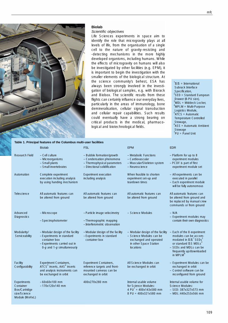
1ISIS = InternationalSubrack InterfaceSpecification,
2SED = Standard EuropeanDrawer (8-PU size),
3MDL = Middeck Locker,
4MPLM = Multi-PurposeLogistics Module,
5ATCS = AutomaticTemperature ControlledStowage,
6ASS = Automatic AmbientStowage
7PU = Panel Unit
BiolabScientific objectivesLife Sciences experiments in space aim toidentify the role that microgravity plays at alllevels of life, from the organisation of a singlecell to the nature of gravity-resisting and -detecting mechanisms in the more highlydeveloped organisms, including humans. Whilethe effects of microgravity on humans will alsobe investigated by other facilities (e.g. EPM), itis important to begin the investigation with thesmaller elements of the biological structure. Atthe science community’s behest, ESA hasalways been strongly involved in the investi-gation of biological samples, e.g. with Biorackand Biobox. The scientific results from theseflights can certainly influence our everyday lives,particularly in the areas of immunology, bonedemineralisation, cellular signal transductionand cellular repair capabilities. Such resultscould eventually have a strong bearing oncritical products in the medical, pharmaco-logical and biotechnological fields.
mfc
109
Table 1. Principal features of the Columbus multi-user facilities
Biolab FSL EPM EDR
Research Field – Cell culture – Bubble formation/growth – Metabolic Functions – Platform for up to 8– Microorganisms – Condensation phenomena – Cardiovascular experiment modules– Small plants – Thermophysical parameters – Muscular/Skeleton system – PCDF is part of first– Small invertebrates – Directional solidification – Neuroscience experiment module set
Automation Complete experiment Experiment execution When feasible to shorten – All experiments can beexecution including analysis including analysis experiment set-up and executed in parallelby using handing mechanism teardown times – Each experiment module
will be fully autonomous
Telescience All automatic features can All automatic features can All automatic features can All automatic features can be altered from ground be altered from ground be altered from ground be altered from ground and
be replaced by manual crewcommands or from ground
Advanced – Microscope – Particle image velocimetry – Science Modules – N/ADiagnostics – Experiment modules may
– Spectrophotometer – Thermographic mapping contain their own diagnostics– Interferometric observation
Modularity/ – Modular design of the facility – Modular design of the facility – Modular design of the facility – Each of the 8 experimentServiceability – Experiments in standard – Experiments in standard – Science Modules can be modules can be accom-
container box container box exchanged and operated modated in ISIS1 SEDs
2
– Experiments carried out in in other Space Station or standard ISS MDLs3
0-g and 1-g simultaneously locations – SEDs and MDLs can befrequently up/downloadedin MPLM
4
Facility Experiment Containers, Experiment Containers, All Science Modules can – Experiment Modules can beConfigurability ATCS
5inserts, AAS
6inserts reference targets and front- be exchanged in orbit exchanged in orbit
and analysis instruments can mounted cameras can be – Control software can bebe exchanged in orbit exchanged in orbit reconfigured from ground
Experiments – 60x60x100 mm 400x270x280 mm Internal usable volume Internal usable volume forContainer – 170x120x140 mm for Science Modules: Science Modules:Box/Cartridge 4 PU
7= 400x143x580 mm – SED: 387x327x573 mm
size/Science 8 PU = 400x321x580 mm – MDL: 440x253x566 mmModule (WxHxL)

110
The current Biolab concept is that of a multi-user facility for conducting biological experimentson cells, microorganisms, small plants andsmall invertebrates, as well as research inbiotechnology (Figure 3). The design respectsthe science recommendations, the outcome ofthe scientific and feasibility studies (e.g. Phase-A/B), the experience gained from facilities flown previously, and the requirements andpossibilities offered by the Space Station.
Facility description and operationBiolab is divided physically and functionally intotwo sections: the automated section in the leftside of the rack, and the manual section,including the BioGlovebox, in the right side. Inthe automated section, also known as the CoreUnit, all activities are performed automaticallyby the facility after manual sample loading bythe crew. By implementing such a high level of
r bulletin 102 — may 2000 bull
automation, the demand on crew time isdrastically reduced. The manual section, inwhich all activities are performed by the crewthemselves, is mainly used for sample storageand specific crew activities. The biologicalsamples are contained in standard ExperimentContainers (ECs), which offer standard externalinterfaces with Biolab, an approach that hasbeen well-proved with Biorack. The internalvolume available to experimenters is60x60x100 mm for the standard container, butthe larger Advanced Experiment Container(170x120x140 mm) is also available. Biolab’smain features are indicated in Table 1.
The biological samples, with their ancillaryitems, will be transported from the ground toBiolab either already in the ECs or in small vialsif they require temperatures as low as –80°C,taking advantage of the ESA-developed MELFIfreezer. Once in orbit, samples already in ECswill be manually inserted into Biolab forprocessing, while frozen samples need to be
thawed in the ExperimentPreparation Unit (EPU) installedin the facility’s Bioglovebox.
Once the manual loading iscompleted, the automatic
processing of the experimentscan start. These experiments will
be run in parallel on the two centrifuges,one at 0 g and the other at 1 g for reference.
During the experiment, the handling mechanism
Figure 3. The Biolab multi-user facility. (ESA/D. Ducros)
Figure 5. The Biolab Engineering Model under integration. (ESA/MMS-F)

111
Among the subsystems, one of the firstelements to be manufactured was a set of ECs.Great care was taken to ensure that theirconstruction materials are bio-compatible withthe widest range of biological samples. In thisrespect, the industrial consortium benefitedfrom the results of the Experiment ContainerStandardisation (ECS) study, a GSTP study thatidentified a set of standard items for use in ECs.
The Centrifuges (Figure 6) were manufacturedearly in the Biolab development plan, to ensuresmooth integration inside the complexIncubator. Each centrifuge is equipped with acentral gas slip-ring to supply its six ECs with acontrolled atmosphere. Biolab’s slip-ring had tofulfil stringent requirements in terms of reducedtorque, reduced leakage and material bio-compatibility, combined with a low-pressure
will transport the samples to Biolab’s diagnosticinstruments. With the aid of teleoperations, thescientists on the ground can participate in thispreliminary analysis process. Typical experimentdurations can be between a few days and afew months.
Industrial organisation and developmentstatusBiolab’s Phase-C/D was initiated in December1997 with Matra Marconi Space of Toulouse (F)as prime contractor. The consortium is shownin Figure 4. The manufacturing of all EngineeringModel (EM) subsystems has been completedand the EM is under integration (Figure 5).Completion of the functional and performancetest campaign is planned for the second half of2000. The Flight Model will be delivered by theend of 2001.
mfc
Biolab
Fluid Science Laboratory
European Physiology Modules
European Drawer Rack &European Stowage Rack
Biolab Prime & AIVMatra Marconi Space (F)
Training ModelOHB (D)
Science ReferenceModel
Rovsing (DK)
Co-EngineeringIncubator
Handling MechanismDASA (D)
BioGloveboxBradford Eng. (NL)
TCU & ATCSNTE (E)
Analysis InstrumentsGSE
Carlo Gavazzi Space(I)
SoftwareMMS (F)
Laptop DevelopmentLogica (B)
Cold PlatesVerhaert (B)
Cold PlatesVerhaert (B)
StructureFerrari (I)
Thermal S/SVerhaert (B)
HandlingMechanism Arm
Rosys (CH)
SyringesTreff (CH)
Hamilton (CH)
Life Support SystemCentrifuge Rotors
OHB (D)
Thermal S/SVerhaert (B)
Drive UnitThermal Housing
Ferrrari (I) FSL Prime & AIVAlenia Aerospazio (I)
Human Computer InterfaceSoftware
Scientific & Operations SupportMARS (I)
Optical Design SupportOfficine Galileo (I)
Environmental/Thermal ControlOptical Reference TargetsReference Test Container
DASA-Dornier (D)
Power Control UnitVideo Management Unit
Front Mounted Cameras & HarnessOHB System (D)
Facility Core Element with OpticalDiagnostics and CentralExp. Modules, Fluid GSE
Verhaert (B)
Rack Secondary StructuresMechanical GSE
Sener (E)
Master Control UnitLap Top Unit
Laben (I)
Electrical GSECarlo Gavazzi Space (I)
EPM Prime & AIVOHB System (D)
EPM CarrierSamples Collection Drawer
OHB (D)
EGSERPDA MODS
Carlo Gavazzi Space (I)
Training ModelEPM Drawer Mechanism
Verhaert (B)
Bone Analysis ModuleInnovision (D)
CIR (CH)
Multi ElectrodeEncephalograph Module
EREMS (F)
EDR/ESR Prime & AIVAlenia Aerospazio (I)
Video/Data ProcessingOHB (D)
Temperature AcquisitionKayser-Threde (D)
ThermalBradford Engineering (NL)
ISIS DrawersOCI (CH)
Figure 4. Industrialparticipants in thedevelopment of theColumbus multi-userfacilities

Figure 6. One of the twocentrifuges for Biolab.
(ESA/OHB)
supply gas. Since no suitable commercial slip-rings were available on the market, the criticaldevelopment was supported in Phase-B by adedicated breadboard, which proved thedesign’s acceptable performance. Biolab’sScience Team supported the IndustrialConsortium by performing dedicated bio-compatibility tests.
Owing to the nature of Biolab’s experiments,the BioGlovebox includes an ozone generatorto clean and sterilise some of Biolab’ssubsystems. The ozone is created by a high-voltage alternating electrical discharge throughthe air, breaking down molecular oxygen intoatomic oxygen. The generator will be used to:
– sterilise Biolab before starting experiments,to avoid contamination from the Stationinfecting the experiment;
– clean and sterilise a sample spillage, to avoidbiological contamination growing uncontrol-lably within Biolab.
Developed specifically for Biolab, this ozonegenerator may find a large commercial marketon the ground, where it can quickly and easilysterilise medical tools.
User-support activities and selectedexperimentsIn the frame of the user-support activities, theEPU’s Phase-B/C/D began early in 2000 withthe prime contract awarded to Verhaert (B). Thebreadboarding tests will be completed by thesecond half of 2000.
Following the 1998 International Life SciencesResearch Announcement (LSRA), twoexperiments are in the definition phase, withBiolab as one of the selected possible facilities.The first experiment will provide insight into the
repair processes in mammalian cells inmicrogravity, after these cells are damaged byknown doses of radiation. The results will beimportant in assessing the risks of spaceflight,since there is a synergistic link between spaceradiation and microgravity. One set of damagedcells will be studied in space by fluorescencemicroscopy using telescience, while thesecond set will be deep-frozen for analysis onthe ground.
The second candidate experiment will studythe effect of spaceflight on the virulence potentialof bacteria that are infectious to humans. Thiswill also be an important contribution to risk-assessment for space travellers, since thespace environment may alter the pathogenicpotential of the bacteria. This is of particularimportance because microgravity negativelyaffects the human immune system.
Fluid Science Laboratory (FSL)Scientific objectives
Fluid science experiments in spaceare designed to study dynamicphenomena in the absence ofgravitational forces. Under microgravityconditions, such forces are almosteliminated, including their effects influid media such as gravity-drivenconvection, sedimentation andstratification, and fluid static pressure.This allows the study of fluid dynamiceffects that are normally masked bygravity, such as the diffusion-controlled heat and mass transfer incrystallisation processes – theabsence of the normally dominantconvective flow processes results inreduced defect density.
The absence of gravity-drivenconvection eliminates the negativeeffects of density gradients
(inhomogeneous mass distribution) that alwaysarise on Earth in processes involving heattreatment, phase transitions, diffusive transportor chemical reactions. Convection in terrestrialprocesses is a strong perturbing factor, theeffects of which are seldom predictable withgreat accuracy and which dominate heat andmass transfer in fluids.
The ability to control such processes is stilllimited. Their full understanding requires furtherfundamental research by conducting well-defined model experiments for the testing anddevelopment of related theories under micro-gravity. This will allow the optimisation ofmanufacturing processes on Earth andimprovement in the quality of high-valueproducts such as semiconductors.
r bulletin 102 — may 2000 bull
112

113
mfc
ESA has already been involved in studying fluidscience phenomena under microgravityconditions for several years, notably with theBubble, Drop and Particle Unit (BDPU) facilitythat produced important results from severalSpacelab missions.
Facility description and operationFSL is illustrated in Figure 7. The kernel of thefacility consists of the Optical DiagnosticsModule (ODM) and the Central ExperimentModules (CEM), into which the ExperimentContainers (ECs) (Figure 8) are sequentiallyinserted and operated. Together, thesemodules represent the Facility Core Element(FCE), which is complemented by the functionalsubsystems for system and experiment control,power distribution, environmental conditioning,and data processing and management.
In order to cope with the experimentobservation requirements, a set of opticaldiagnostics is integrated in FSL,including:
– visual observation in two axes (y, z) with direct registration via electronic imaging and photographic back-up via Front Mounted Cameras (FMCs)providing high speed, high resolutionand colour recording;
– background, sheet and volumeillumination with white light andmonochromatic (laser) light sources;
– particle image velocimetry, including liquidcrystal tracers for simultaneous velocimetryand thermometry;
– thermographic (infrared) mapping of freeliquid surfaces (also via FMC);
– interferometric observation in two axes (y, z)by convertible interferometers with activealignment:- holographic interferometer;- Wollaston/shearing interferometer;- Schlieren mode combined with shearing
mode;- Electronic Speckle Pattern Interferometer
(ESPI).
In addition to the integrated system, FlightSupport Equipment (FSE) will be availableonboard: spare parts, special tools andconsumables such as cleaning agents, the
Figure 7. The Fluid Science Laboratory multi-user facility (right). (ESA/D. Ducros)
Figure 8. The Engineering Model of the FSLExperiment Container (above). (ESA/DASA)

Figure 9. The breadboard ofthe FSL Microgravity
Vibration IsolationSubsystem (MVIS) with the
Facility Core Element beingtested during a parabolic
flight. (CSA)
FMCs and the Optical Reference Targets (ORT)for calibration of the experiment and diagnosticequipment before an experiment run.
For each experiment or experiment category,an individually developed EC will be used.Stored in the ESR during non-operationalphases, each EC will be inserted by the crewinto the CEM drawer, where it will undergo anexperiment and diagnostics calibration cyclebefore any process activation. Each EC, with atypical mass of 30-40 kg and standarddimensions of 400x270x280 mm, providesample volume for accommodating the fluid cellassembly, including the process stimuli andcontrol electronics. It may also beequipped with dedicated experimentdiagnostics to complement the standarddiagnostics provided by FSL itself.
The control concept for system andexperiment operation provides foralternative modes comprising fullyautomatic experiment processing,even during certain communicationoutage phases such as regular Loss OfSignal, semi-automatic processing ofdefined experiment subroutines, andfully interactive step-by-step commandkeying. All operating modes can betriggered either by the flight crew or from the ground, thus ensuring the possibility of quasi-real-time tele-operation (telescience).
Industrial organisation anddevelopment statusFSL’s Phase-C/D contract was signedin April 1998. The industrialconsortium, shown in Figure 4, is ledby Alenia Aerospazio (I) as primecontractor. The Engineering Models for most of the subsystems have been completed. The system EMprogramme will be completed by the end of2000. The Flight Model will be completed bythe end of 2001.
There are particular technical challenges indesigning the diagnostics and the scientificdata management system. The combination offour different convertible and state-of-the-artinterferometers offers very high flexibility forexperiment observation and diagnostics but,on the other hand, inevitably increasescomplexity. It requires not only a very denseand compact layout but also a high end-to-endoptimisation effort, in view of the manifoldtechnical and scientific performances required.
Potential upgrades, partly resulting from new technology developments, are under
investigation for a decision in the near future ontheir implementation:– the active Microgravity Vibration Isolation
Subsystem (MVIS, Figure 9), using magneticlevitation. Each Principle Investigator (PI) canactivate the subsystem to isolate hisexperiment from the g-jitter perturbationinduced by Space Station dynamics. MVIS isbeing developed by the Canadian SpaceAgency;
– diagnostics, replacing the bulky and heavythermoplastic film camera with the now-mature technology of photorefractive crystalsin combination with digital holographicinterferometry.
Experiments selectedBased upon the 1998 Physical Science AO,about 15 peer-recommended experimentproposals, from various scientific and industrialresearch organisations all over Europe, requireFSL. Even in the USA, a growing interest wasfound in running experiments on FSL. Definitionstudies of experiment containers will beinitiated for the following experiments in view oftheir maturity:
– Development of Advanced Foams andHydrodynamics of Wet FoamsThese experiments will provide knowledgeto European industry on the developmentand production of advanced foams byovercoming the limits imposed by variousinstabilities experienced in normal gravity.
r bulletin 102 — may 2000 bull
114

115
mfc
Several industries including the oil industryare participating.
– Fundamental and Applied Studies ofEmulsion StabilityThese experiments will investigate thephysio-chemical aspect of surfaces insupport of emulsion science technology ofspecial interest for the food, cosmetic andpharmaceutical industries.
– Convection and Interfacial Mass ExchangeThese experiments are devoted to the studyof mass-transfer processes throughinterfaces. These phenomena are of theutmost importance for chemical engineeringprocesses. Thirteen European and two USgroups are involved. Industrial applicationsare expected for thermal-control equipmentin space industries.
– Simulation of Geophysical Flows underMicrogravityThese experiments will investigate, on asmall scale, large-scale motions in the outerlayer of the Earth and in the atmospheres ofgiant planets. The results will be used toimprove models predicting thermalconvection in those situations.
All of the other experiment proposals willundergo further definition work.
European Physiology Modules (EPM)Scientific objectivesHuman physiology experiments inmicrogravity not only increase knowledge ofhow the human body reacts to long exposureweightlessness, but also contributes to abetter understanding of Earth-relatedproblems such as ageing processes,osteoporosis, balance disorders, biomedicalresearch, cancer research and muscle wastingin limb immobilisation (casts) and bed-rest.Investigations have been conducted for manyyears and ESA has successfully flown facilities,such as Sled and Anthrorack on severalSpacelab missions.
In order to evaluate the data collected onboard,it is essential that reference (or baseline) databe collected both before the mission and afterthe crew returns to Earth. For this purpose,EPM will provide a Baseline Data Collection(BDC) system that includes functional copies ofthe onboard instruments. The BDC will beeasily transportable to ensure that theequipment is available at the crew locationshortly before launch and immediately afterlanding.
NASA’s Human Research Facility (HRF) will besimilar to EPM. The first of two ISPRs will belaunched early in the Space Station assemblysequence and the second somewhat later,although still well before Columbus. ESA andNASA plan to collocate EPM and HRF inColumbus, thereby allowing experiments usingscientific instruments from both.
Facility description and operationThe multi-user EPM (Figure 10) consists of acomplement of Science Modules (SMs) plusthe Carrier infrastructure to support theircoordinated operation. The Carrier providesdata handling, thermal control and mechanicalaccommodation for the SMs. A maximum ofnine active Science Modules can beaccommodated at any one time, allowing fordifferent Module sizes.
Figure 10. The EuropeanPhysiology Modules multi-user facility. (ESA/D. Ducros)

Figure 12. The breadboardmodel of EPM’s Bone
Analysis Module.(ESA/Innovision)
Figure 11. The EPM Multi-Electrode EEG
Measurement Module cap.(ESA/EREMS)
The SMs are accommodated in standarddrawers of sizes of 4 PU and 8 PU (1 PU = 4.45cm). They interface with the rack via astandardised guide system that simplifies theon-orbit exchange and installation of new SMs.All rack-mounted SMs are cooled via a ductedair system provided as part of the Carrier.
EPM’s modularity allows a very flexibleconfiguration of SMs. Based on inputs from theFacility Science Team, it has been decided toinclude the following instruments in the initialconfiguration:
– Multi-Electrode EEG Measurement Module(MEEMM)MEEMM will be used for different types ofnon-invasive brain function investigations.During experiments, the test subject wears acap equipped with up to 128 electrodes(Figure 11) connected to sensitive, low-noiseelectronics to measure the very small signalsat very high sampling rates. In order togenerate appropriate stimuli, different stressorscan be used that are available onboard.Examples are the Virtual EnvironmentGenerator and muscle stimulators(associated with NASA’s Human ResearchFacility). Together with EPM’s ELITE-S2module (see below), it will be possible toperform experiments that simultaneouslymeasures brain activity and body movements.MEEMM also contains an ambulatory unitthat will allow measurements to be madewhile the test subject is performing otheractivities or asleep. The data are recorded ona removable hard disk and later transferredto the EPM Data Management System to besent to ground.
– Bone Analysis Module (BAM)Bone loss is a severe problem in long-duration space flights. Understanding therelated dynamics and developing effectivecountermeasures are important require-ments for flying long missions. BAM will studythe efficacy of various countermeasures byevaluating changes in the ultrasoundtransmission properties of the heel bone(Figure 12). BAM is based on a commercialsystem, where the foot is placed in an openwater tank. This approach is unsuitable forspace, so instead water-filled latex bags areplaced on each side of the foot. A testcampaign using the prototype and otherbone densitometers on a large number ofsubjects will verify the new design.
– Sample Kit DrawerThis drawer will help the crew to take bloodand urine samples. Most samples must bestored onboard in a controlled environmentfor later download to the ground for analysis.Limited analysis can also be performedonboard.
Apart from the above hardware beingdeveloped as part of the EPM contract,National Agencies will contribute the followinginstruments:
– CardiolabCardiolab (CNES and DLR) comprisesdifferent equipment supporting cardio-vascular research, e.g. electro-cardiogramand blood pressure holter, portable Doppler,air plethysmograph, cardiopres;
– ELITE-S2The ‘Elaboratore Immagini Televisive–Space2nd generation’ ELITE-S2 (ASI and CNES) isa facility for the quantitative analysis ofhuman kinematics in weightlessness. Fourcameras mounted around the test subjectrecord the movements. Special softwaredetects sensor positions mounted on the
r bulletin 102 — may 2000 bull
116

117
Standard European Drawers (SEDs) andstandard Shuttle-type Middeck Lockers(MDLs). It is a flexible experiment carrier since itis not dedicated to a specific discipline. EDR’smain design drivers are modularity andstandardisation. The use of standard drawersand lockers assure quick turnaround andthereby increased flight opportunities for themicrogravity user community. Missionpreparation activities are estimated to take6 months. In particular, SEDs and MDLs can beexchanged in orbit.
subject and from this recreates a 3D modelthat can be used to analyse the movementpatterns in detail.
– XSMI/PPMIThe Xenon Skin Blood Flow MeasurementInstrument (XSMI) and the PhysiologicalPressure Measurement Instrument (PPMI)(Danish space agency) are two smallambulatory instruments to measure skinblood flow and physiological pressures suchas central venous and oesophageal pressures.
The EPM contribution to NASA’sHuman Research FacilityESA is developing a number ofinstruments for contribution to NASA’sHRF, thereby allowing their earlier in-orbit deployment than possible aboardColumbus. One is a collaboration withNASA to develop a Pulmonary FunctionSystem (PFS). This will consist of fourbuilding blocks, two provided by NASA(Gas Analyser System for MetabolicAnalysis Physiology; Gas Distribution System)and two by ESA (Photoacoustic AnalyserModule, PAM; Pulmonary Function Module).Together, these blocks will make up a highlyflexible and sophisticated pulmonary andcardio-vascular research tool. PAM is based ona European niche technology and it will bereduced in volume compared with the earlierversion (Figure 13). This development hashelped the commercial application of thistechnology in hospitals.
Industrial organisation and developmentstatusOHB (D) was awarded the prime contract inMay 1999 for Phase-B/C/D; the industrialconsortium is shown in Figure 4. For the EPMContribution to the HRF-2, the primecontractor is Innovision (DK). EPM’s PreliminaryDesign Review is planned by mid-2000.Breadboardings of MEEMI and BAM areunderway. Delivery of the Flight Model isexpected by mid-2002.
Experiments selectedOne experiment selected for Definition from the1998 International LSRA requests the use ofPFS. Its objective is to evaluate cardiac fluidvolume regulation. The 1999 LSRA is the first toinclude EPM’s capabilities. Of the 43 proposalsinvolving human research, there are 13 thatcould make use of the EPM and/or PFSinstrumentation.
European Drawer Rack (EDR)EDR is a multi-user facility (Figure 14) providingthe infrastructure for accommodating andservicing experiment modules housed within
mfc
Figure 13. ThePhotoacoustic AnalyserModule (PAM, left) for EPM.The earlier version is at right.(ESA/Innovision)
Figure 14. The EuropeanDrawer Rack multi-userfacility, including the FASTand PCDF experimentmodules. (ESA/D. Ducros)

Facility description and operationEDR provides small and modular experimentsin SEDs and MDLs with access to Columbusservices. Its main features are shown in Table 1.A fundamental EDR goal is to support thedevelopment of smaller sub-rack payloads(Class-II) by providing accommodation resourcesand rapid-turnaround flight opportunities.EDR’s design is oriented to maximise user-friendliness and flexibility of experimentaccommodation and operation.
EDR’s SED and MDL concept allowsexperiment module access to the EDRcentralised services, ranging from thedistribution of system resources (e.g. power,data, venting and cooling) to dynamic resourcemanagement (e.g. simultaneous access tosystem resources by more than oneexperiment module). EDR includes all thecapabilities for monitoring and controlling thefacility, its operations and resource usageenvelopes, as well as the capability foroperating the experiments. Its main subsystemfunctions are implemented in five units: Power;Thermal; Processing Control and Command;Video Management Units; Laptop. It supportssimultaneous control of up to eight differentexperiments, i.e. one for each drawer andlocker within the allowed resource budgets.EDR is reconfigurable in flight to allow theexchange of SED/MDL experiments on-orbit. Itis designed to need only minimal crewintervention.
The SEDs are compatible with the InternationalSubrack Interface Standard (ISIS). This ensuresmechanical compatibility between the NASAExpress Transport Rack (ETR) and EDR and, assuch, allows rapid EDR payload turnaround byusing ETR for EDR SED up/download. TheStandard ISS Lockers (MDLs) are mechanicallycompatible with the ISS Shuttle Middeckinterfaces and ETR. This allows rapid EDRexperiment locker turnaround by using eitherthe Shuttle or ETR for EDR MDL up/download.
Industrial organisation and developmentstatusEDR completed Phase-B in July 1999 andPhase-C/D will begin in 2000. Some bread-boarding activities were completed duringPhase-B. The industrial consortium is led byprime contractor Alenia Aerospazio (I); theindustrial consortium is shown in Figure 4.
ExperimentsA set of potential experiment modules for EDRaccommodation has been identified:– FAST (Facility for Adsorption and Surface
Tension Studies) is an ESA multi-user facilitythat has already flown on the STS-95/
Spacehab mission (October 1998). It is nowundergoing refurbishment for flight on STS-107/Spacehab in March 2001 and is acandidate for reflight in EDR for long-durationexperiments in Columbus. FAST is accom-modated in two MDLs (Figure 14).
– PCDF (Protein Crystallisation DiagnosticsFacility) is an ESA multi-user facility underdevelopment to provide in-depth knowledgeand understanding of the protein crystalgrowth process under microgravity. PCDFcrystal growth processing may use eitherbatch or dialysis crystallisation. Protein crystalgrowth takes place in four reactors with thetemperatures and temperature gradients ofthe protein solutions individually controlled.The built-in advanced diagnostics systemallows the scientists to operate theexperiments in a fully automatic mode (time-line and parameter controlled) or in a semi-automatic mode (telescience from ground).
The PCDF consists of two elements to beaccommodated in EDR (Figure 14): theProcess Unit (PU) and the Electronic Unit (EU).The PU accommodates the process chamberin which the four reactors are contained. Thereactors contain the protein and salt solutions.The PU incorporates two temperature controllayers. The EU accommodates the controlcircuitry for experiment execution and thePCDF diagnostics system, which incorporatesa monochrome digital video camera with awide field of view and microscope optics, theDynamic Light Scattering (DLS) system and aMach-Zehnder interferometer. For futureapplications, the PCDF can be expanded tosupport osmometry and pH measurement. ThePU will be accommodated in the new ISS MDL,and the EU in a SED. For harvesting the proteincrystals and reloading the protein and saltsolutions on the ground, the complete PU hasto be transported from/to Columbus within theSpace Shuttle’s middeck. This allows powerprovision to guarantee temperature controlduring transport, early access to the PU forprotein crystal retrieval and late access for thePU installation in the middeck for uploading.This is mandatory, as proteins are sensitive andfast-deteriorating macromolecules.
PCDF is being developed under ESA’sMicrogravity Programme EMIR-2. The completedbreadboarding has confirmed the design. Theprime contractor is DASA/Dornier (D) withsubcontractors Aerospatiale Matra Lanceurs(AML, F), Laben (I), Chevalier Photonics (B) andALV (D).
European Stowage Rack (ESR)ESR is a passive multi-user facility to allow
r bulletin 102 — may 2000 bull
118
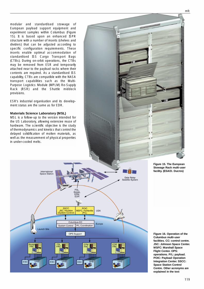
Figure 15. The EuropeanStowage Rack multi-userfacility. (ESA/D. Ducros)
Figure 16. Operation of theColumbus multi-userfacilities. CC: control centre.JSC: Johnson Space Center.MSFC: Marshall SpaceFlight Center. OPS:operations. P/L: payload.POIC: Payload OperationIntegration Center. SSCC:Space Station ControlCentre. Other acronyms areexplained in the text
modular and standardised stowage ofEuropean payload support equipment andexperiment samples within Columbus (Figure15). It is based upon an enhanced ISPRstructure with a number of inserts (shelves anddividers) that can be adjusted according tospecific configuration requirements. Theseinserts enable optimal accommodation ofstandardised ISS Cargo Transport Bags(CTBs). During on-orbit operations, the CTBsmay be removed from ESR and temporarilyattached near to the payload racks where theircontents are required. As a standardised ISScapability, CTBs are compatible with the NASAtransport capabilities such as the Multi-Purpose Logistics Module (MPLM) Re-SupplyRack (RSR) and the Shuttle middeckprovisions.
ESR’s industrial organisation and its develop-ment status are the same as for EDR.
Materials Science Laboratory (MSL)MSL is a follow-up to the version intended forthe US Laboratory, allowing extensive reuse ofhardware. The scientific objective is the studyof thermodynamics and kinetics that control thedelayed solidification of molten materials, aswell as the measurement of physical propertiesin under-cooled melts.
mfc
119

120
Experiments may be executed from the UserHome Bases (UHBs, primarily universities andresearch centres), with overall coordination bythe FRC and, when required, by the ESCs. Thisdecentralised payload processing is seen asthe most efficient approach for implementationof Columbus utilisation.
Each mission increment will last 3-6 monthsand the selection of successive experimentcomplements will follow a similar schedule. Theequipment required to conduct the experimentswill be uploaded by the MPLM aboard theSpace Shuttle.
Commercial use of the facilitiesIn view of the request by the ESA Council atMinisterial Level in 1999 to propose a schemefor commercialising the Space Station, theMFC Programme has completed a preliminarystudy with a consortium of MMS (F; Biolab),Alenia (I; FSL), DASA-RI/Dornier (D; MSL) andOHB (D; EPM) on defining a strategic plan forattracting commercial users. The goal of thestudy will be to generate income for ESA fromconventional fields (such as R&D centres) andfrom ‘unconventional’ fields such as education.Possible fields of utilisation for the facilities areindicated in Figure 17. A follow-up phase willconcentrate on some pathfinder projects toprove the effectiveness of the proposed planwith the identification of specific commercialcustomers.
AcknowledgementsThe authors wish to thank three members ofthe ESA/ESTEC Microgravity and SpaceStation Department: J.C. Ives (EPMcontribution to the HRF); V. Pletser (PCDF); andC. Schmidt-Harm (FAST). r
r bulletin 102 — may 2000 bull
erforscht kritischer Punkt
CommercialApplicationPossibilities
Commercial
Aims
Crystal growthmechanisms
solved
High-strengthmaterials
developed
MedicalConcerns
High-TechMaterial
Enzyme structurerevealed: medicine
from the drawing board
Effect mechanismsin the Immune system
researched InnovativeProcesses
biologicalattraction/signal
chains researches
Theoryconfirmed:
critical point
AppliedResearch
new theoriesto stimulatecell-growth
Diagnosis processdisproved: caloric
Nystagmus
Step toOsteoclasis
identified
Breakdown effects:Marangoni-convection
BasicResearch
Knowledge
ImprovedProducts
Research
BasicResearch
Health
weight-lessness
g = 0
theoryB =2g Rdensity
matched = 0
smallcolumns
R 0
EPM
Biolab
MSL
FSL
EPM
Biolab
MSL
FSL
An industrial definition Phase-A/B is expectedto begin in the second half of 2000. The start ofPhase-C/D will be decided at the end of thedefinition phase.
Operation of the facilitiesDuring development of the facilities, thescience teams, user representatives (e.g.Facility Responsible Centres and User OperationSupport Centres) and astronauts are helping tooptimise the designs. At the end of the FSL,Biolab, EPM and EDR development phases,their final acceptance will take place using theRack Level Test Facility (RLTF) to simulate theColumbus interfaces. Once Columbus is inorbit, this will be the only means of acceptingpayloads before uploading them to the SpaceStation.
Figure 16 shows a scenario for the scientificoperation of the multi-user facilities aboardColumbus. Each laboratory will make use of adedicated Facility Responsible Centre (FRC)that serves as the interface between all of thescientific users and the appropriate payloadcontrol centre. These FRCs will also preparethe timelining for the experiments and performthe first level of troubleshooting duringoperations. The prime contractor for eachfacility will support a second level of trouble-shooting and provide sustaining engineeringsupport.
The following FRCs have been selected: MUSC(D) for Biolab, MARS (I) for FSL, CADMOS (F)for EPM and ESTEC (NL) for EDR. For somecomplex experiments, Experiment SupportCentres (ESCs) will provide specific expertise indefined scientific fields. Some have alreadybeen identified: ETH (CH) for Biolab, DARIVA (E)for FSL and DAMEC (DK) for EPM.
Figure 17. Possible fields ofutilisation for the MFC
facilities (ESA/DASA)