Embed Size (px)
Citation preview
REFERENCIA: Ferro, L., Giugliano, P., Galbiati, P., Memoli, F., Giavani, C., & Maiolo, J. (2007). The Electric Arc Furnace of Tenaris Dalmine: from the application of the new technolo-gies of digital electrode regulation and multipoint injection to the Dynamic Control of the Process. In 16th IAS Steelmaking Conference, Rosario, Argentina (pp. 59-72).
THE ELECTRIC ARC FURNACE OF TENARIS DALMINE: FROM THE APPLICATION OF THE NEW TECHNOLOGIES OF DIGITAL
ELECTRODE REGULATION AND MULTIPOINT INJECTION TO THE DYNAMIC CONTROL OF THE PROCESS
Luis Ferro1
Paolo Giugliano1
Paolo Galbiati1
Francesco Memoli2 Cesare Giavani3 Joseph Maiolo4
ABSTRACT The EAF of Tenaris Dalmine, located in the area of Bergamo in the North of Italy, is a 20 ft furnace with a tapping ca-pacity of 105 short tons of liquid steel. Downstream of the EAF, the Meltshop is equipped with two ladle furnaces, one vacuum degasser and two continuous casting machines for round-bars – from 5” to 15” diameter – for the production of seamless pipes, the main product of the Tenaris Group. During the last five years, this EAF has been equipped with Tenova’s most innovative technologies for scrap melting and refining, specifically: Electrode Digital Regulation, multipoint oxygen and carbon injection systems, a complete and modern Level-2 automation system and recently the Goodfellow EFSOP® system. The automation system supervises the complete operation of the Meltshop, from the preparation of the scrap buckets right through to the production of the round bars. This paper describes the integration of all of these technologies, their proper use for management of the electrical and chemical set-points to maximize their synergy and Tenova’s goals for dynamic control of the EAF process. The ultimate goal of this last mentioned step in EAF process development is the use of real-time analysis of furnace operation to achieve optimum EAF performance.
1 Tenaris Dalmine Piazza Caduti 6 Luglio 1944, 1 - Dalmine, Bg. (Italy) Tel.: +39 (035) 560.111 – Fax: +39 (035) 560.3827 [email protected] 2 Tenova Metal Making Via Monte Rosa, 93 - Milano (Italy) Tel: +39 (02) 4384.7892 – Fax: +39 (02) 4384.7696 [email protected] 3 Tenova Melt Shops Via Monte Rosa, 93 - Milano (Italy) Tel: +39 (02) 4384.7950 [email protected] 4 Tenova Goodfellow Mississauga Road 7070 – Mississaauga, On (Canada) Tel.: +1 (905) 567-3030 [email protected]
1. TENARIS GROUP Tenaris is the leading global manufacturer and supplier of tubular products and services used in the drilling, completion and production of oil and gas; in process and power plants; and in specialized industrial and automotive applications. Through its integrated global network of manufacturing, R&D, and service facilities, Tenaris works to meet its clients needs for the timely supply of high performance products in increasingly complex environments. Employees (Oct. 5, 2006): 21,500 Annual manufacturing capacity: Steel pipes: 6,000,000 tons Steel Plants: Tenaris Dalmine (Italy), Tenaris Siderca (Argentina), Tenaris Tamsa (Mexi-co) Stock exchange listings: New York (USA), Buenos Aires (Arg), Milan (Ita), Mexico City (Mex) Tenaris’s environmental policy is based upon the principle of sustainable development. Following the introduction of our Health, Safety and Environment (HSE) Policy, Tenaris have been working on the implementation of an integrated HSE management system. The management system is a set of processes and practices that help Tenaris to constantly improve its environmental performance. This management system follows the guidelines of international standards such as ISO 14000 and OHSA 18000, applying eco-efficiency and integral safety concepts throughout the system, from prod-uct design and industrial investment right through to operations and logistics. The integrated system is currently being implemented in four major facilities. Tenaris adheres to worldwide sustainability principles and guidelines developed for the steel industry, such as: a) Investment in New Processes and Products – recognizing that innovation is crucial for long-term industrial projects, Tenaris has established an Investment Master Plan to revamp all its mills and improve its processes and products; b) Greenhouse Gas Emissions – Tenaris supports the �ndustry’s search for innovative solutions to reduce greenhouse gas emissions over the life-cycle of steel products; c) Material Efficiency and Energy Intensity – Tenaris continually reviews its operations to maximize the efficiency of energy resources, the re-use of by-products and the appropriate treatment and disposal of waste, emissions and effluents; e) Steel Recycling: Steel can be recycled, but more importantly its desirable properties can be renewed; f) Employee training – Tenaris has created TenarisUniversity, a corporate university that looks to continuously offer training to all employees on a global level. Education is a funda-mental tool for achieving long term sustainability. [ref.: 1]
Historical Milestones 1909 Dalmine begins manufacturing seamless steel tubes in Italy. 1924 Dalmine is listed on the Milan Stock Exchange. 1935 Agostino Rocca, the future founder of the Techint Group of Companies, becomes Managing Director at
Dalmine. 1953 Tamsa is listed on the Mexican Stock Exchange. 1954 Tamsa begins operations in Mexico and Siderca in Argentina. Both are constructed by Techint. 1958 Siderca is listed on the Buenos Aires Stock Exchange. 1967 Tamsa lists on the American Stock Exchange, becoming the first Mexican company to list on a U.S. Stock
Exchange through an American Depositary Receipts (ADR) program. 1993 Siderca acquires a controlling interest in Tamsa and forms a strategic alliance. 1996 Siderca acquires a controlling interest in Dalmine following its privatisation. With Tamsa, this strategic alli-
ance becomes DST. 1998 Tamsa establishes Tavsa with Corporación Venezolana de Guayana to take over Sidor’s seamless steel tube
mill. 2000 Siderca and NKK Corporation form NKKTubes to take over NKK’s seamless tube manufacturing business
at Keihin Works (Tokyo, Japan). Siderca leases Algoma Steel’s seamless steel tube plant and begins operat-ing AlgomaTubes.
2001 The Tenaris brand name is introduced replacing DST. Siderca lists on the NYSE market. 2002 Tenaris S.A., a company organized in Luxembourg, becomes the group holding company following an ex-
change offer for the shares of Siderca, Tamsa and Dalmine and is simultaneously listed on the New York, Milan, Buenos Aires, and Mexican stock exchanges.
2004 Tenaris acquires control of Silcotub, a Romanian manufacturer of seamless steel pipes. 2006 Tenaris establishes a strong presence in USA through the acquisition of Maverick Tube Corp. At the same
time, its presence in Canada is expanded with Prudential and establishes a presence in Colombia through TuboCaribe.
2. TENARIS DALMINE
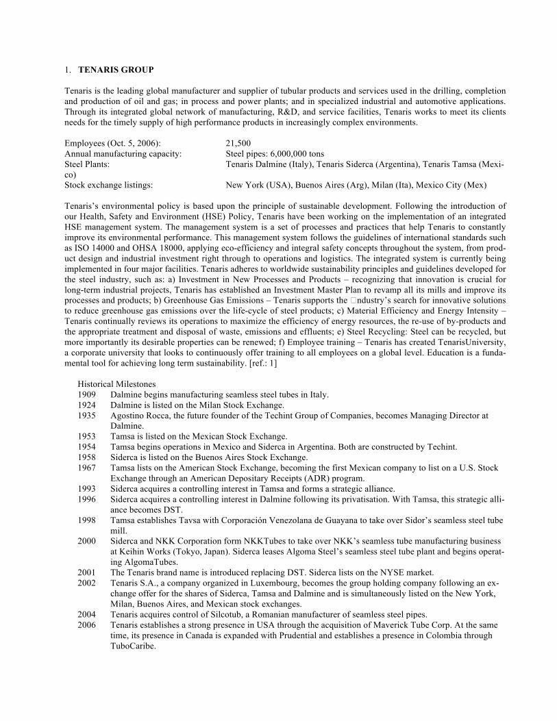
An important part of Tenaris’s manufacturing capacity is located in Italy at the state-of-the-art Dalmine Seamless Pipe Mill in Dalmine, Bergamo, and its four satellite mills: Arcore (hot finished rolled tubes), Costa Volpino (cold formed precision tubes), Piombino (welded tubes for water and gas) and Sabbio Bergamasco (gas cyl-inders). All together, our Italian manufacturing facilities include a steel shop, two mandrel mills, a rotary expander, a pilger mill, extensive finishing facilities, a cold-drawing mill and an auto components facility having an annual production capacity of 950,000 tons of seamless. Since its founding in 1906, Dalmine has played a sig-nificant role in the development of Italian industry and today manufactures seamless pipes that are used in a wide range of engineering, mechanical, structural and energy applications. TenarisDalmine has a workforce of more than 3,000 employees and covers an area of 1,523,000 square meters, 540,000 of which hold buildings and fac-
tories. Dalmine produces seamless pipes, with outside diameters from 11/16 inch (17.2 mm) to 28 inch (711 mm), in carbon and alloy steel. Dalmine’s product line also includes tapered poles, made from seamless tubes, for long-distance power lines and electric traction. Tenaris’s process for producing seamless steel pipe is based on the Electric Arc Fur-nace, Ladle Furnace, Vacuum Degassing and Continuous Casting process. The Electric Arc Furnace is charged by se-lected scrap and varying percentages of pig iron, sponge iron (DRI) and Hot briquette iron (HBI). The last two alterna-tive iron sources are used mainly in the Mexican (Tenaris Tamsa) and Argentinean (Tenaris Siderca) facilities, but not in Tenaris Dalmine. Regarding the EAF process, the following paragraphs will describe the specifics of the Tenaris process. At the continu-ous caster, liquid steel is cast into round bars with diameters ranging from 145 mm (½ ft) to 395 mm (15.5 inches). The bars are conditioned and prepared to be sent to the mills where they are cut into sections. The billets are loaded into the rotary furnace, where they are heated about 1300º C. After leaving the rotary furnace, the billet is pierced in the piercing mill producing what is known as “pierced material”. Subsequently, the pierced material passes through the continuous rolling mill to reduce and stretch its wall thickness, resulting in another pipe called continuous shell. The last rolling step takes place at the Stretch Reducing Mill, where the pipe's final diameter and wall thickness are achieved. Once the speci-fied sizes are set, the pipe is subjected to heat treatment to achieve the physical and mechanical properties required by the customer. Finally, before delivery to the customer, the pipes are inspected (through non-destructive tests) and threaded [ref.: 2].
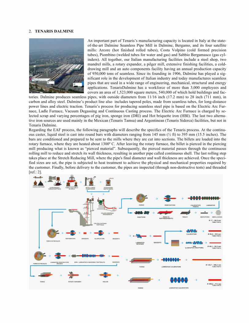
3. THE ELECTRIC ARC FURNACE OF TENARIS DALMINE AND THE EQUIPMENT INSTALLED TenarisDalmine’s Meltshop is located 50 km east of Milan (Italy). Its scrap yard has a total area of 13,300 m2 and a ca-pacity of 38,000 tons. The uncovered scrap yard is equipped with six 15-ton bridge cranes which load 2 bucket charges per heat. Each crane has its own independent weighing system. Two drying and soft pre-heating stages warm the scrap to 200°C before charging to the furnace. The EAF is equipped with three burners, three fixed-wall oxygen lances and three fixed-wall carbon injectors as well as a door lance. Productivity of more than 130 t/h is achieved with tap-to-tap times of about 40 minutes. Secondary metallurgy facilities include 2 LMFs (25 MVA each) and one vacuum degasser. Ferroalloys are added automatically. Steel is kept stirred by 2 porous plugs in the ladle bottom. Two continuous casting machines (1 vertical and 1 curved) cast round bars in the range 148-395 mm.
Dalmine EAF equipment details:
• Furnace type Tagliaferri EAF, 1991 • Furnace diameter and volume 20 ft (6,100 mm) – 3200 cf
(90 m3) • Tapping system EBT – swivelling flap • Platform type Tagliaferri conventional
half-platform • Roof swinging system rail and pivot on independ-
ent foundation • Charging system conventional – two buck-
ets • Transformer: 100 MVA (500/1000 V) • Reactor: 85 MVA (Off-load Tap
changer) • Regulation System: TDR-H with harmonics
control, 2005 • Oxygen Multipoint Lances: 3 KT Oxygen Lances, 2001 • Carbon Injectors: 3 KT Carbon Injectors, 2001 • Other chemical devices: 2 burners and 1 water cooled door lance • Automation: Level 1 & Level 2 by Tenaris Dalmine
4. CURRENT EAF PERFORMANCES Today, Dalmine’s EAF is performing at its best ever with the lowest key performance indicators (KPI), in terms of cost and the highest in terms of productivity. Tenaris Dalmine’s EAF has always been characterized by a very short tap-to-tap time and power-on time; with a refining period that has always been less than ten minutes. Given that, it is easy to understand why this EAF has been called “the melting machine” rather than arc furnace. Dalmine’s operation, updated January 2007, is as follows:
• Tap to Tap 39.7 min • Power On 31.3 min • Power Off 8.4 min
In order to achieve their desired steel grades Dalmine’s tap temperature is typically greater than 3010oF to accommodate, on average, 3 to 3.5 tons of Ferro Alloys (mainly FeSiMn, FeSi, FeMn, FeCr, Al, FeMo, etc.). Furthermore, approxi-mately 30% of the production is sent to vacuum degasser where free board volume is an important consideration. In fact, for these so-called “VD” heats, the liquid steel in the ladle cannot be greater than 90 tons while for deep vacuum heats, the liquid steel is at a maximum 85 tons. Consistent average parameters for the bulk 70% of the production are as follows:
• Metallic Charge 109.7 short ton 99.5 metric ton • Tapped Steel 102.5 short ton 93 metric ton • Yield scrap to liquid 93.4% • Liquid in ladle, with Fe-Alloys 105.3 short ton 95.5 metric ton • Tapping Temperature 3011°F 1661 °C • Average Tapping Carbon 0.05 %
The following table details Tenaris Dalmine’s monthly average consumptions on a liquid-steel basis (as of January 2007). The values are close to the industry standard for this type of production: Consumptions (based on liquid steel):
• Electrical Energy 344.7 kWh/short ton 380 kWh/metric ton • Electrode consumption 2.76 lb/short ton 1.38 kg/metric ton • Oxygen (Lancing) 717.6 scf/short ton 22.4 Nm3/metric ton • Oxygen (Burners) 426.1 scf/short ton 13.3 Nm3/metric ton • Total Oxygen 1143.7 scf/short ton 35.7 Nm3/metric ton • Natural Gas (Lancing) 121.7 scf/short ton 3.8 Nm3/metric ton • Natural Gas (Burners) 118.5 scf/short ton 3.7 Nm3/metric ton • Total Natural Gas 240.2 scf/short ton 7.5 Nm3/metric ton
• Injected Carbon 9.8 lb/short ton 4.9 kg/metric ton • Lump Anthracite 8.4 lb/short ton 4.2 kg/metric ton
Referring to the EAF performances of 2003 [ref.: 3], it is interesting to note that the total carbon addition (charged and injected anthracite) has been decreased by 4.6 lb/short ton; indicating that Dalmine has been successful in reducing their use of additional charge carbon. Further analysis of these figures also indicates the optimization of oxygen injection which is necessary so as not to jeopardize the final oxygen ppm content of the bath – a strict requirement of this process. In fact, it is necessary to keep final oxygen to 800-900 ppm before tapping. Oxygen usage above the noted value has been found to compromise this target. As detailed elsewhere the efficient utilization of the oxygen through an optimized supersonic nozzle [ref.: 4, 5] has been applied such that the injection of supersonic oxygen is limited to 426 scf/ton in the last ten minutes of the heat.

The following table details the energy sinks of the Dalmine EAF: At Dalmine, fluxes are added via a chute pipe through a fifth hole in the roof of the furnace. Both CaO and CaO/MgO are added batch-wise for each of the two bucket charges. The Bi-nary Basicity Index of the resulting EAF slag is always above 2.2, the same for the Quaternary Basicity Index and about 1.7 for the Ternary basicity Index. The goal is to work as much as possible with an MgO saturated slag. A typical slag analysis is detailed below:
• CaO 27.5 % • Al2O3 4.1 % • SiO2 12.1 % • MgO 9.2 % • FeO 35.8 %
• MnO 7.6 % • Cr2O3 2.7 % • P2O5 0.4 % • TiO2 0.3 % • Other 0.3 %
The above operating performance clearly shows that Tenaris Dalmine is among the best operating steel factories in Eu-rope and the world [ref.: 6] 5. ELECTRIC ARC FURNACE OPTIMIZATION DURING THE LAST TWO YEARS During the last two years, a process-wide optimization program has been executed in the EAF area to meet the compa-ny’s goals of cost reduction and productivity increase. This section details various activities that have been carried out with the aim of improving the operation of the EAF. Overall, the operation was performing fine but areas for improve-ment were identified. Adjustments to KT oxygen injection rates Since initial installation (2001), the typical rate of oxygen injection through the KT oxygen lances was 950 scfm (1600 Nm3/h) [ref.: 7]. This rate has been increased to 1180 scfm (2000 Nm3/h) in order to enhance the decarburization rate during the very short refining period. This increase in oxygen lance rate required a simple change of the KT lance nozzle copper tip [ref.: 8], from the old nozzle of ⅝ inch (16.05 mm) to the new larger ¾ inch (19 mm) inner diameter nozzle.
Changes to the Valve Stand Regarding the valve stand, only minor changes were needed to adapt the existing oxygen racks to the new flows. The only requirement was a change in the proportional valves’ “cv” characteristic. The final configuration of the oxygen valve stand is currently providing:
• Three main oxygen lines up to 1300 scfm for the three KT Oxygen Lances • Three secondary oxygen lines up to 600 scfm for the same three KT Oxygen Lines • Two oxygen lines up to 600 scfm for the two conventional burners • One oxygen line up to 2300 scfm for the door lance • One oxygen line up to 1300 scfm in stand-by
New KT Carbon Injection The chemical package, installed in 2001, included a Silo Plus dispenser with triple, independent, lines for carbon injec-tion. One of these three lines was directed to the door lance, which has the capability to inject carbon. The other two were directed to the two KT Carbon Injectors, installed on the EBT and behind phase III or “C” and in close proximity to the KT Oxygen lances. Recent modifications on the carbon injection system consisted of the exclusion of the carbon
ENERGY OUTPUT (metrics) Heat in liquid steel 61.55% 388.8 kWh/tls Heat in slag 8.78% 55.5 kWh/tls Heat to the off gasses 19.58% 123.7 kWh/tls Furnace water-cooling 6.41% 40.5 kWh/tls Electrical losses 1.83% 11.6 kWh/tls Radiation and convection 1.82%
11.5 kWh/tls
Total output 631.6 kWh/tls
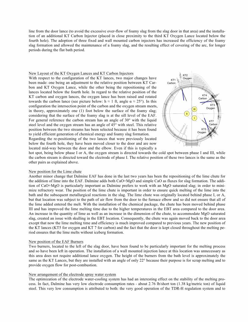
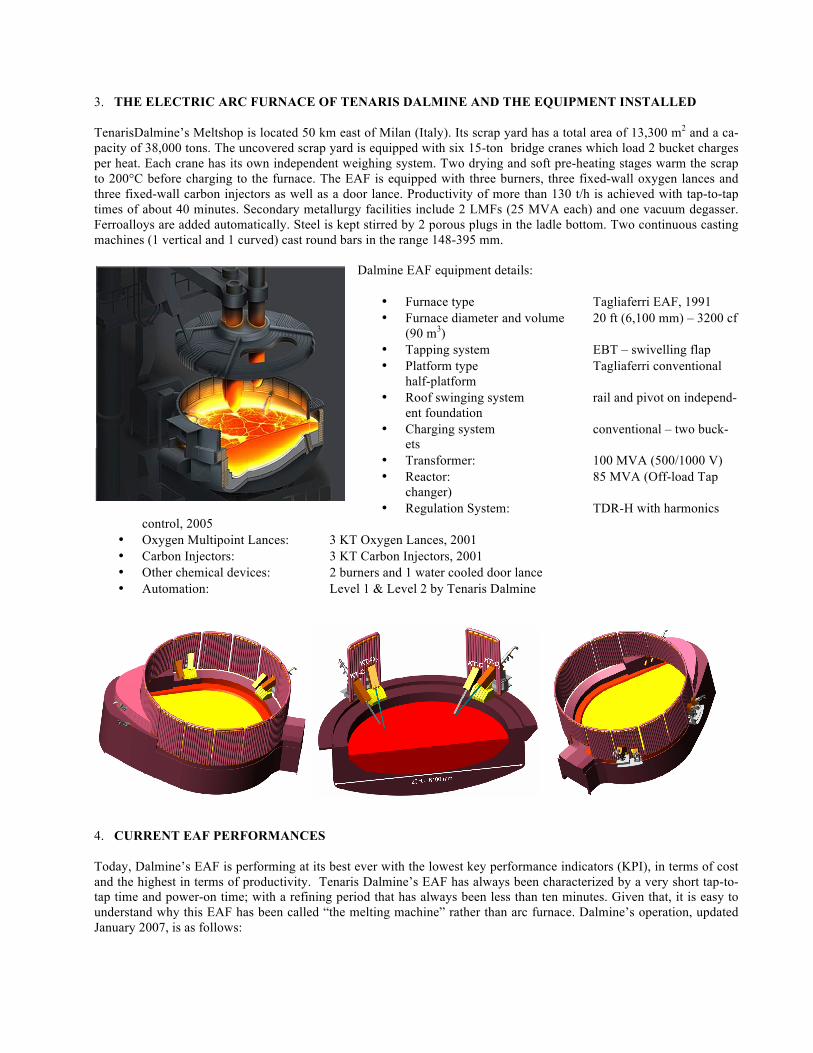
line from the door lance (to avoid the excessive over-flow of foamy slag from the slag door in that area) and the installa-tion of an additional KT Carbon Injector (placed in close proximity to the third KT Oxygen Lance located below the fourth hole). The adoption of three fixed and wall mounted carbon injectors has increased the efficiency of the foamy slag formation and allowed the maintenance of a foamy slag, and the resulting effect of covering of the arc, for longer periods during the flat bath period. New Layout of the KT Oxygen Lances and KT Carbon Injectors With respect to the configuration of the KT lances, two major changes have been made: one being an adjustment to the relative position between KT Car-bon and KT Oxygen Lance, while the other being the repositioning of the lances located below the fourth hole. In regard to the relative position of the KT carbon and oxygen lances, the oxygen lance has been raised and rotated towards the carbon lance (see picture below: h ≈ 1 ft, angle α ≈ 25°). In this configuration the intersection point of the carbon and the oxygen stream meets, in theory, approximately one (1) foot below the surface of the foamy slag; considering that the surface of the foamy slag is at the sill level of the EAF. For general reference the carbon stream has an angle of 30° with the liquid steel level and the oxygen stream has an angle of 45° with steel. This relative position between the two streams has been selected because it has been found to yield efficient generation of chemical energy and foamy slag formation. Regarding the re-positioning of the two lances that were previously located below the fourth hole, they have been moved closer to the door and are now located mid-way between the door and the elbow. Even if this is typically a hot spot, being below phase I or A, the oxygen stream is directed towards the cold spot between phase I and III, while the carbon stream is directed toward the electrode of phase I. The relative position of these two lances is the same as the other pairs as explained above. New position for the Lime chute Another minor change that Dalmine EAF has done in the last two years has been the repositioning of the lime chute for the addition of lime into the EAF. Dalmine adds both CaO+MgO and simple CaO as fluxes for slag formation. The addi-tion of CaO+MgO is particularly important as Dalmine prefers to work with an MgO saturated slag; in order to mini-mize refractory wear. The position of the lime chute is important in order to ensure quick melting of the lime into the bath and the subsequent metallurgical reactions in the slag. The lime chute was originally located behind phase I, or A, but that location was subject to the path of air flow from the door to the furnace elbow and so did not ensure that all of the lime added entered the melt. With the installation of the chemical package, the chute has been moved behind phase III and has improved the lime melting time due to the higher temperatures in the EBT area compared to the door area. An increase in the quantity of lime as well as an increase in the dimension of the chute, to accommodate MgO saturated slag, created an issue with skulling in the EBT location. Consequently, the chute was again moved back to the door area except that now the lime melting time and efficiency is much improved compared to previous years. The new position of the KT lances (KT5 for oxygen and KT 7 for carbon) and the fact that the door is kept closed throughout the melting pe-riod ensures that the lime melts without iceberg formation. New position of the EAF Burners Two burners, located to the left of the slag door, have been found to be particularly important for the melting process and so have been left in operation. The installation of a wall mounted injection lance at this location was unnecessary as this area does not require additional lance oxygen. The height of the burners from the bath level is approximately the same as the KT Lances, but they are installed with an angle of only 22° because their purpose is for scrap melting and to provide oxygen flow for post-combustion. New arrangement of the electrode spray water system The optimization of the electrode water-cooling system has had an interesting effect on the stability of the melting pro-cess. In fact, Dalmine has very low electrode consumption rates - about 2.76 lb/short ton (1.38 kg/metric ton) of liquid steel. This very low consumption is attributed to both: the very good operation of the TDR-H regulation system and to
KT1Carbon
KT2Oxygen
KT4Carbon
KT3Oxygen
KT7Carbon
KT5Oxygen
II
III
I
the electrode cooling system. Previously cooling of the electrodes was done with only water while in the last few months the water rate has been decreased and compressed air has been added; resulting in more effective cooling and greater stability of the arc. Chemical set point for a “blind post-combustion” practice At Tenaris Tamsa, post-combustion in the EAF is controlled, in real time, by Tenova Goodfellow EFSOP® system. The interchange of “know-how” and data between the two sister plants of the Tenaris Group have enabled Dalmine to im-plement post-combustion blindly (without feedback control). Learning from the Tamsa experience, the KT Injection lances are used in the melting phase as burners and as supersonic oxygen injectors only during flat bath operation. A particular period of the heat, which is in the transition phase between melting and refining, has been recognized as the more critical phase of furnace operation. During this transition period oxygen and methane rates have been set so as to maximize as much as possible the formation of CO2 in the freeboard of the EAF. The benefits of this practice led to the decision of installing the Tenova Goodfellow EFSOP® system in order to incre-ment even more post combustion and methane injection efficiency. The EFSOP® system has been recently installed at the fourth hole and the optimization phase under closed loop control just started. New practice of utilization for the door oxygen lance In the past Dalmine used its door lance in a very conventional manner; however today, it is used for a very short period during the heat. In fact, the lance is kept off for the first twenty minutes of power-on (during melting). In this way, the slag door is closed during melting so as to minimize the amount of fresh air entering the freeboard. The lance is then used for about four minutes as a burner (oxygen and methane) to clean scrap from the slag door and then for about five more minutes during refining to complete decarburization of the steel bath. New layout of the EBT horizontal panel Another minor change, from the mechanical point of view, but very important from the process point of view has been the addition of a hydraulic door for EBT panel opening. The hole on the horizontal panel was previously closed with a device that the operator had to manually open for filling with sand. The new system is a small hydraulically operated door that not only simplifies post-tapping inspection of the EBT and filling of the tap hole with sand but also helps keep the inspection window closed during power-on-time. Before imple-mentation of this simple device, operators had to be mindful of excessive foamy slag generation causing over-flow of slag from the EBT panel and subsequent delays during the power-off time. Since the implementation of the protective hydraulic door, the operator is free to generate the necessary foamy slag (as requested by feedback of harmonics tied to the digital electrode regulation). Reduction in lump anthracite usage Due to the efficiency of the KT oxygen injection system, lump carbon addition has been reduced from 2200 lb (1000 kg) to 880 lb (400 kg) per heat. Originally, 2200 lbs. of carbon were necessary so as to avoid over-oxidation of the bath. The new position of the lances and the utilization of the post-combustion practice mentioned above has permitted a reduction in the amount of lump anthracite carbon used. Utilization of Pig Iron in the Charge Mix TenarisDalmine has always been a major pig iron user, due to requirements in terms of: steel grade quality, low power on times and the relevant utilization of energy generation from the decarburization reactions. In spite of the many changes, pig iron usage has remained constant at 11-12% during the optimization campaign. New requirements for the dimensions of big pieces of scrap An important implementation that caused a dramatic effect on the melting time has been the reduction in size of large pieces of scrap and pot, ladle and tundish skull returns. For example, the tundish skulls were previously cut into three yielding pieces of maximum 6 ½ ft (2m) skulls. The TenarisDalmine EAF is very quick in power-on-time and each mi-nute delay on the net tap to tap results in losses in profit. It has been decided to cut the skulls into 5 pieces having a maximum dimension of 20 inches. The additional time required by the scrap yard for processing return skulls and for cutting down scrap to less than 20 inches is justified by a more stable melting operation and directly influences EAF de-lays for EBT cleaning New EAF electrical and chemical profiles.
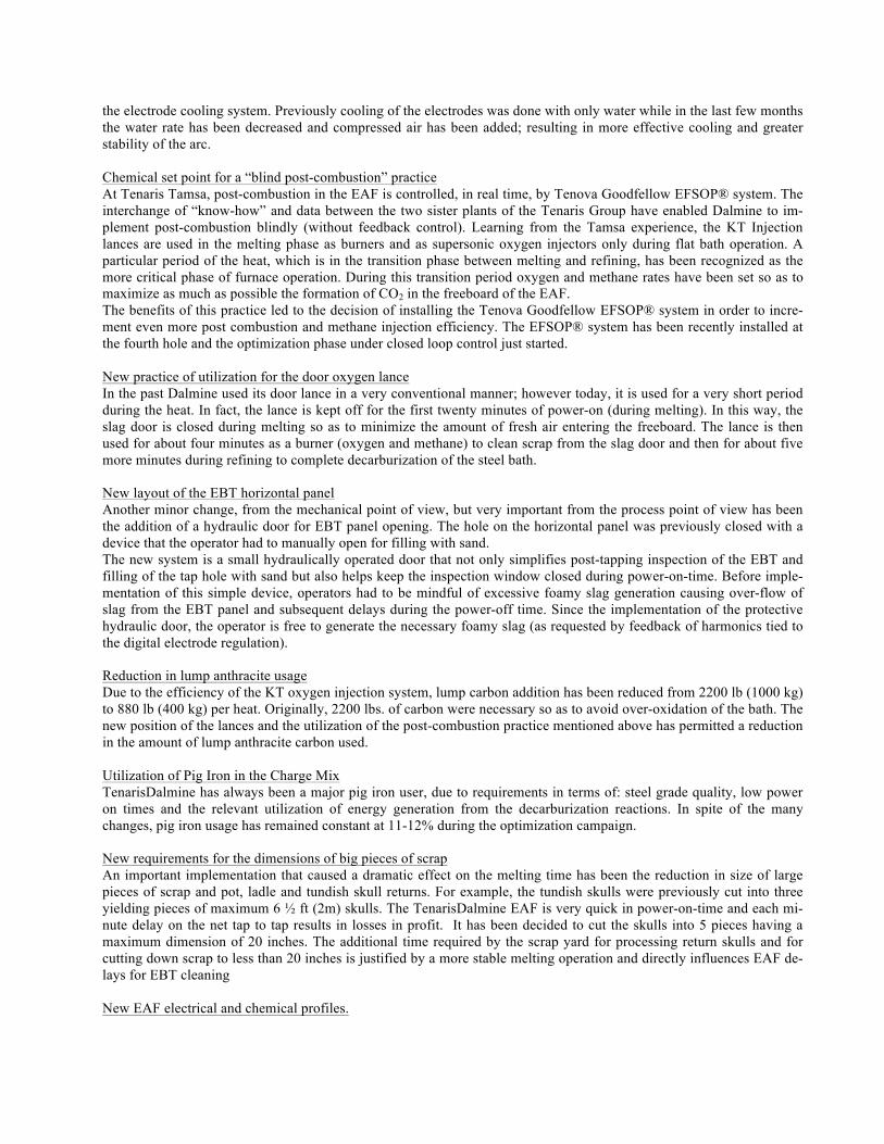
The two figures below summarize TenarisDalmine’s new electrical and chemical energy practices. The figures are plots of electrical power (on the left) and oxygen and methane (on the right), as functions of time.
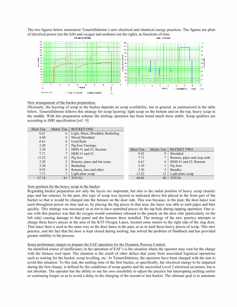
New arrangement of the bucket preparation. Obviously, the layering of scrap in the bucket depends on scrap availability, but in general, as summarized in the table below, TenarisDalmine follows this strategy for scrap layering: light scrap on the bottom and on the top, heavy scrap in the middle. With this preparation scheme the melting operation has been found much more stable. Scrap qualities are according to ISRI specification [ref.: 9]
Short Ton Metric Ton BUCKET ONE 6.61 6 Light, Sheet, Shredded, Busheling 4.40 4 Mixed Shredded 6.61 6 Used Rails 2.20 2 Pig Iron Turnings 3.30 3 HMS #1 and #2, Russian Short Ton Metric Ton BUCKET TWO 7.71 7 HMS #1 and #2 9.92 9 Shredded
13.22 12 Pig Iron 7.71 7 Returns, pipes and crop ends 2.20 2 Returns, pipes and bar crops 6.61 6 HMS #1 and #2, Russian 3.30 3 Busheling 3.30 3 Pig Iron 9.92 9 Returns, bars and other 3.30 3 Bundles 7.71 7 Light plate scrap 13.22 12 Light plate scrap
67.18 61 TOTAL 44.06 40 TOTAL New position for the heavy scrap in the bucket Regarding bucket preparation not only the layers are important, but also is the radial position of heavy scrap (mainly pipe and bar returns). In the past, this type of scrap was layered as indicated above but placed in the front part of the bucket so that is would be charged into the furnace on the door side. This was because, in the past, the door-lance was used throughout power on time and so, by placing the big pieces in that area, the lance was able to melt pipes and bars quickly. This strategy was necessary so as not to have unmelted pieces on the tap hole during tapping operation. One is-sue with this practice was that the oxygen would sometimes rebound to the panels on the door side (particularly on the left side) causing damage to that panel and the burners there installed. The strategy of the new practice attempts to charge these heavy pieces in the area of the KT5 Oxygen Lance, located some meters to the right side of the slag door. That lance then is used in the same way as the door lance in the past, so as to melt those heavy pieces of scrap. This new practice, and the fact that the door is kept closed during melting, has solved the problem of flashback and has provided greater stability to the process. Some preliminary targets to prepare the EAF operation for the Dynamic Process Control. An identified source of inefficiency in the operation of EAF’s is the situation where the operator may wait for the charge with the furnace roof open. The situation is the result of other delays that come from associated logistical operations such as waiting for the bucket, scrap levelling, etc. At TenarisDalmine, the operators have been charged with the aim to avoid this situation. To this end, the melting time of the first bucket, or specifically, the electrical energy to be imparted during the first charge, is defined by the conditions of scrap quality and the associated Level 2 electrical set points, but is not absolute. The operator has the ability to use his own sensibility to adjust the practice but interrupting melting earlier or continuing longer so as to avoid a delay in the charging of the second or last bucket. The ultimate goal is to automate
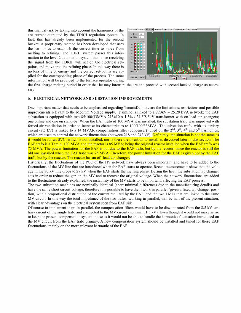
this manual task by taking into account the harmonics of the arc current outputted by the TDRH regulation system. In fact, this has already been implemented for the second bucket. A proprietary method has been developed that uses the harmonics to establish the correct time to move from melting to refining. The TDRH system passes this infor-mation to the level 2 automation system that, once receiving the signal from the TDRH, will act on the electrical set-points and move into the refining phase. In this way there is no loss of time or energy and the correct set-points are ap-plied for the corresponding phase of the process. The same information will be provided to the furnace operator during the first-charge melting period in order that he may interrupt the arc and proceed with second bucked charge as neces-sary. 6. ELECTRICAL NETWORK AND SUBSTATION IMPROVEMENTS
One important matter that needs to be emphasised regarding TenarisDalmine are the limitations, restrictions and possible improvements relevant to the Medium Voltage supply. Dalmine is linked to a 220kV – 25.28 kVA network; the EAF substation is equipped with two 85/100/33MVA 215±10 x 1.5% / 31.5/8.5kV transformer with on-load tap changers; one online and one on stand-by. When the EAF trafo of 100 MVA was installed, the substation trafo was improved with forced air ventilation in order to increase its characteristics to 100/100/33MVA. The substation trafo, with its tertiary circuit (8,5 kV) is linked to a 14 MVAR compensation filter (condenser) tuned on the 2nd, 3rd, 4th and 5th harmonics; which are used to control the network fluctuations (between 218 and 242 kV). Definitely, the situation is not the same as it would be for an SVC; which is not installed, nor is there the intention to install as discussed later in this section. The EAF trafo is a Tamini 100 MVA and the reactor is 85 MVA; being the original reactor installed when the EAF trafo was 75 MVA. The power limitation for the EAF is not due to the EAF trafo, but by the reactor; since the reactor is still the old one installed when the EAF trafo was 75 MVA. Therefore, the power limitation for the EAF is given not by the EAF trafo, but by the reactor. The reactor has an off-load tap changer. Historically, the fluctuations of the PCC of the HV network have always been important, and have to be added to the fluctuations of the MV line that are introduced when the EAF starts to operate. Recent measurements show that the volt-age in the 30 kV line drops to 27 kV when the EAF starts the melting phase. During the heat, the substation tap changer acts in order to reduce the gap on the MV and to recover the original voltage. When the network fluctuations are added to the fluctuations already explained, the instability of the MV starts to be important, affecting the EAF process. The two substation machines are nominally identical (apart minimal differences due to the manufacturing details) and have the same short circuit voltage; therefore it is possible to have them work in parallel (given a fixed tap changer posi-tion) with a proportional distribution of the current required by the EAF, and the two LMFs that are linked to the same MV circuit. In this way the total impedance of the two trafos, working in parallel, will be half of the present situation, with clear advantages on the electrical system seen from EAF side. Of course to implement them in parallel, the compensation filters would have to be disconnected from the 8.5 kV ter-tiary circuit of the single trafo and connected to the MV circuit (nominal 31.5 kV). Even though it would not make sense to keep the present compensation system in use as it would not be able to handle the harmonics fluctuation introduced on the MV circuit from the EAF trafo primary. A new compensation system should be installed and tuned for these EAF fluctuations, mainly on the more relevant harmonic of the EAF.
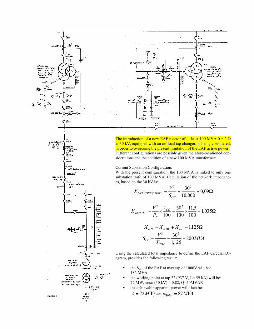
The introduction of a new EAF reactor of at least 100 MVA 0 ÷ 2 Ω at 30 kV, equipped with an on-load tap changer, is being considered, in order to overcome the present limitation of the EAF active power. Different configurations are possible given the afore-mentioned con-siderations and the addition of a new 100 MVA transformer: Current Substation Configuration: With the present configuration, the 100 MVA is linked to only one substation trafo of 100 MVA. Calculation of the network impedanc-es, based on the 30 kV is:
Ω=== 09,0000,103022
)220(CC
kVNETWORK SVX
Ω=×=×=− 035,11005,11
10030
100
22
1CC
NTRAFO
VPVX
Ω=+= 125,11TRNTWTOT XXX
MVAXVSTOT
CC 800125,13022
===
Using the calculated total impedance to define the EAF Circular Di-agram, provides the following result:
• the SCC of the EAF at max tap of 1000V will be: 182 MVA
• the working point at tap 22 (937 V, I ≈ 59 kA) will be: 72 MW, cosφ (30 kV) = 0.82, Q=50MVAR
• the achievable apparent power will then be: MVAMWA kV 87cos72 30 == ϕ
The voltage fluctuation on the 30 kV circuit due to the fluctuation of the reactive power during EAF operation will be:
%25.680050
===Δ Δ
CCQQV
Therefore, as per the above calculation, the introduction of the 100 MVA reactor will not be so beneficial for the EAF as the max apparent power will be only limited to 87 MVA. In fact 72 MW are already supplied with the 85 MVA reactor always in overload. New Configuration of the Substation with Transformers in Parallel: In this configuration, the EAF trafo is linked to the trafo parallel in the substation, as per the previous description. Tak-ing into account that one substation trafo has been considered at 100 MVA while the other with the nominal 85 MVA; the calculation of the network impedances (based on 30 kV) is:
Ω= 09,0)220( kVNETWORKX Ω=− 035,11TRAFOX Ω=− 218,12TRAFOX
Ω=+
++
=+ 56,0
218,11
035.111
111
21
21
TT
TT
XX
X
Ω=+=+= + 65,056,009,021 NETWORKTTTOT XXX MVAXVSTOT
CC 138565,03022
===
Using the calculated total impedance to define the EAF Circular Diagram, provides the following result:
• the SCC of the EAF at max tap of 1000V will be : 201,82 MVA • the working point at tap 22 (937 V, I ≈ 58 kA) will be : 78 MW, cosφ (30 kV) = 0.82, Q=54MVAR • the achievable apparent power will then be : MVAMWA kV 95cos78 30 == ϕ
The voltage fluctuation on the 30 kV circuit due to the fluctuation of the reactive power during EAF operation will be:
%89.3138554
===Δ Δ
CCQQV
The above calculation shows that in addition to the installation of a new EAF reactor, putting two substation trafos in parallel would provide the necessary power to the EAF. In fact, in a parallel configuration the EAF trafo would be used at 95% of its possible apparent power and the voltage fluctuation on the MV line would be in the range of acceptable voltages; which for Dalmine is not an HV network requirement but an MV requirement to maintain a stable 30kV line. As indicated, this would be possible only with the addition of a new reactor. The new reactor would be selected with an on-load tap changer that would provide greater flexibility in the electrical system. Just for reference, the installation of an SVC with right characteristics of power and design, not considering the parallel configuration of the substation trafos, would have a stabilizing effect on the 30 kV MV line. In order to supply the EAF trafo up to 79 MW at tap 22 with cosφ = 0.82 would require that the EAF trafo be used at an apparent power of 97 MVA. In the case of SVC installation and also the parallel trafo configuration, the working point on the EAF trafo would be 80.5 MW with a 99% utilization of the apparent power of the EAF trafo. These simple calculations show that the installation of an SVC, whose cost is certainly not negligible, could not possibly be justified by a mere 2 MW increase over the comparatively minor substation modifi-cations. 7. DYNAMIC PROCESS CONTROL IN THE TENARIS WAY The goal of developing a Dynamic Process Control, as intended by Tenaris for the EAF, started in Tamsa with the instal-lation of the Goodfellow EFSOP® (Expert Furnace System Optimization Process) System and now continues in Dalmine. At Tamsa process optimization, based on adjustments to the carbon\oxygen practice, fume system changes and
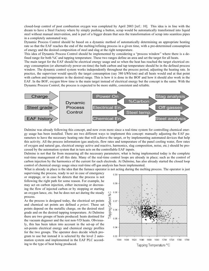
closed-loop control of post combustion oxygen was completed by April 2003 [ref.: 10]. This idea is in line with the dream to have a Steel Factory where by simply pushing a button, scrap would be automatically transformed into liquid steel without manual intervention, and is part of a bigger dream that sees the transformation of scrap into seamless pipes in a completely automated way. Dynamic Process Control should be based on a dynamic method of automatically determining an appropriate heating rate so that the EAF reaches the end of the melting/refining process in a given time, with a pre-determined consumption of energy and the desired composition of steel and slag at the right temperature. This idea of Dynamic Process Control should be implemented by considering a “process window” where there is a de-fined range for both %C and tapping temperature. These two ranges define an area and set the target for all heats. The main target for the EAF should be electrical energy usage and so when the heat has reached the target electrical en-ergy consumption (or alternatively power-on-time) the bath carbon and tap temperature should be in the defined process window. The dynamic control system works independently throughout the process period, adjusting the heating rate. In practice, the supervisor would specify the target consumption (say 380 kWh/ton) and all heats would end at that point with carbon and temperature in the desired range. This is how it is done in the BOF and how it should also work in the EAF. In the BOF, oxygen blow time is the main target instead of electrical energy but the concept is the same. With the Dynamic Process Control, the process is expected to be more stable, consistent and reliable.
DynamicProcessControl
Charge
Steel grade
EAF history
Power On
Electrical En.
Chemical En.
%Carbon
Steel temp.
Slag analysis
Off gasses
Steel analysis
Dalmine was already following this concept, and now even more since a real-time system for controlling chemical ener-gy usage has been installed. There are two different ways to implement this concept: manually adjusting the EAF pa-rameters to have the necessary heating rate that will achieve the target, or by implementing automated devices that help this activity. All the process information (gas analysis, flow rates and temperature of the panel cooling water, flow rates of oxygen and natural gas, electrical energy active and reactive, harmonics, slag composition, noise, etc.) should be pro-cessed by the automation system that in turn acts on the controllable EAF inputs. Dalmine is not that far from measuring all the necessary parameters; what is being implemented today is the complete real-time management of all this data. Many of the real-time control loops are already in place; such as the control of carbon injection by the harmonics of the current for each electrode. At Dalmine, has also already started the closed loop control of chemical energy usage since real-time off-gas analysis has been implemented. What is already in place is the idea that the furnace operator is not acting during the melting process. The operator is just supervising the process, ready to act in case of emergency or stoppage, or in case he detects that the process is not following the right path for some reason. For example, he may act on carbon injection, either increasing or decreas-ing the flow of injected carbon or by stopping or starting an oxygen lance, etc. but he does not act during the steady process. As the process is designed today, the electrical set points and chemical set points are defined a priori. These set points depend on the metallic charge, on the desired steel grade and on the desired tapping temperature. At Dalmine there are two groups of heats produced: heats destined for the vacuum degasser and the rest non-VD heats. Obvious-ly, this has been taken into account in the set-up of the set-points electrical energy and chemical energy profiles for the two groups. The operator does decide which pro-gram to use but instead it is selected by the level 2 auto-mation system and implemented in the EAF PLC accord-ing to the type of heat being produced.

It is also implemented, at Dalmine, the real-time loop that adjusts the actual heating rate according to the process param-eters being measured and the off-gas composition. For now, Dalmine works with dynamic but fixed tables of process set-points. Consequently variations in the charge or on the electrical network from the expected conditions are not taken into account yet to adjust the actual heating rate to achieve the desired heating rate. Oxygen Injection Management: with the implementation of the off-gas measurement system, closed loop on the chemi-cal energy delivery system is implemented so as to optimize post-combustion and other aspects of chemical energy. Fur-ther integration with the arc harmonics closed-loop will be used to address a list of priority items for every event out of the desired process path. Foamy slag management: Dalmine also plans to implement a lime injection system; another key tool in the advancement towards dynamic process control of the EAF. The lime injection system will provide flexibility in the control of flux ad-ditions with dedicated injectors for CaO and CaO/MgO. Foamy slag practice will then be controllable not only through carbon injection, in response to feedback from off-gas composition, electrical harmonics, panel temperatures (represent-ing arc radiation), but also through the injection of lime. It is important to note that for Dalmine foamy slag optimization affects less than one-third of the total power-on-time; the remaining two thirds representing scrap melting time is where most of the efforts will be directed. Electrical system management: a key fundamental task of the dynamic process control system will be to manage the heating rate by acting in real-time on electrical parameters in response to such things like panel cooling water tempera-tures, off-gas composition and temperature, harmonics (measured independently for each electrode) The final necessary component of the dynamic process control system is the real-time measurement of the steel bath temperature. Dalmine, Techint and Centro Sviluppo Materiali S.p.A (CSM) are currently working on the development of such a sensor. CSM, based in Rome, is part of the global R&D network of Tenaris and was established in 1963 by lead-ing mechanical and steel companies as an experimental centre in metallurgy. The research group is a model for innova-tion not only in Italy but throughout Europe. 8. UPCOMING DEVELOPMENTS The Goodfellow EFSOP® – Expert Furnace System Optimization Process – is a proprietary system that uses continuous off-gas analysis, along with process monitoring to optimize and control the use of chemical energy within the electric arc furnace (EAF). Optimization is achieved by adjustments to the electric furnace process (carbon charge practice, in-jected carbon, methane and oxygen), according to analysis of off-gas composition measurements. Further benefits are provided through dynamic control of oxygen and methane in response to real-time off-gas composition. As mentioned earlier in this paper, the EFSOP® system has been installed at TenarisTamsa. Initial EFSOP® optimiza-tion at Tamsa provided a 4.4% reduction in conversion costs (oxygen, methane, electricity and carbon) and a reduction of one minute in power-on-time. Afterwards, in late 2003, Techint installed and commissioned the KT-Chemical pack-age at Tamsa. The Goodfellow EFSOP® system was again used to re-optimize chemical energy usage within the EAF. Ultimately, a reduction in electrical energy (12.3%) and methane consumption (33%) were achieved. Economically, the-se savings outweighed the increase in total carbon usage (11 %) and oxygen consumption (14.6%) and provided an overall 2% reduction in power-on-time (1 minute), considering an increase in tapping weight by 11 % (from 142 to 158) tons liquid steel. Over-oxidation of iron was reduced as demonstrated by a decrease in slag FeO from 40% initially to 32%. Electrode consumption was reduced by 9% [ref.: 11]. At Dalmine the Goodfellow EFSOP® system has been installed and commissioned during the week of June 18, 2007. The patented probe, custom designed, is installed in the primary water-cooled duct of the EAF, on the sliding sleeve, just downstream of the combustion gap. The location and positioning of the probe are such that the off-gas is sampled from within the combustion cone; before dilution with combustion air from the gap. The probe is connected to the analyzer that is located 20 meters away, through a heated line that transports the sample gases avoiding condensation of the water vapour of the fumes. Off-gas real time composition measurements, as well as operational alarms and outputs from the analyzer are tied into the plants PLC via standard I/O. Both analog and digital outputs from the analyzer and digital in-puts to the analyzer are hardwired to the plant’s PLC network. The system consists also of a SCADA/HMI supervisory PC that is the core of the dynamic control of the process. The EFSOP® SCADA system consists of a high-speed com-puter and GE,s iFix SCADA development package. Via connection to the plant’s PLC network, the EFSOP® computer is able to log, not only off-gas composition measurements and analyzer alarms, but also many operational furnace and melt-shop parameters. The SCADA system also performs necessary calculations and sends process set-points back to the
PLCs for the dynamic control of the melting process. Data is archived on the EFSOP® HMI for further analysis and for real-time and historical trending. Operators and plant personnel have access to historical trends of data through customi-zable trending screens. The EFSOP® SCADA system is directly connected with the EAF plc, the KT plc, the fume sys-tem plc and the plant level 2 in order to receive and analyze on real time the parameters that affect the melting process. The EFSOP® system will control on real time the O2 and CH4 injection, through dynamic control of the KT burners and lances, the Carbon injection, through the control of the KT injector, the fume system draft, through the control of the fan speeds and damper positioning. This level of control is the first step that TENOVA has taken toward an advanced EAF dynamic control. The next step involves the installation of novel technology at Dalmine. Over the past while, Tenova Goodfellow has been working to extend the capabilities of the EFSOP® through the development of a dynamic mass/energy balance for the gas-phase of the EAF. In addition to off-gas composition, the model takes as its inputs the rates of oxygen, gas and carbon injected into the EAF and determines: a) rate of off-gas leaving the EAF; b) rate of air in-leakage into the EAF; c) rate of carbon monoxide generated from decarburization and combustion of carbon; d) rate of water inleakage into the freeboard; and e) energy losses from the gas-phase. Off-gas temperature will be measured using a novel sensor based on the infrared emission spectrum of carbon dioxide. Estimates of the off-gas rate of flow will be tied to measurements of static pressure at the fourth hole. Temperature and pressure sensor are planned to be installed during the summer maintenance down time. This second step is a major advance for the complete dynamic control of the EAF. REFERENCES
1. http://www.tenaris.com/en/AboutUs/Env.asp 2. http://www.tenaris.com/TenarisDalmine/en/default.aspx 3. M. Rondi, F. Memoli, “Increase of Productivity in Dalmine Steel Plant through the Application of Innovative Elec-
trical and Chemical Technologies”, La Metallurgia Italiana (Ita), Oct 2003, Vol. 95, no. 10, pp. 53-60 4. F. Memoli, C. Mapelli, P. Ravanelli, M. Corbella, “Simulation of Oxygen Penetration and Decarburisation in EAF
Using Supersonic Injection System”, ISIJ International (Jap), Vol. 44, May 2004, No. 8, pp. 1342-1349 5. F. Memoli, C. Mapelli, P. Ravanelli, M. Corbella, “Evaluation of the Energy Developed by a Multipoint Side-wall
Burner-Injection System during the Refining Period in a EAF”, ISIJ International (Jap), Vol. 44, May. 2004, No. 9, pp. 1511-1516
6. F. Memoli, P. Lückhoff, “Benchmark study of EAF plants using the KT injection system”, Iron & Steel Technolo-gy (Usa), Jul. 2004, vol. 1, no7, pp. 138-145
7. M. Rondi, P. Bosi, F. Memoli, “New electrical and chemical technologies implemented in the Dalmine steel plant”, MPT Metallurgical Plant and Technology International (Ger), Oct. 2002, Vol. 25, no. 5, pp. 44-46, 48, 50-51.
8. V. Köster, F. Memoli, “The advanced KT injection system for high-productivity EAFs”, AISE Steel Technology (Usa), Mar. 2002, Vol. 79, no. 3, pp. 28-35.
9. “Scrap Specifications Circular 2006, Guidelines for Ferrous Scrap: FS-2006”, http://www.isri.org, 2006, pp 15-17 10. J. Maiolo, E. Evenson, O. Negru, L. Ferro, P. Galbiati, P; M.J. Garcia, M. Palma, “Goodfellow EFSOPTM Success-
es at TAMSA, Veracruz”, AISTech 2004: Iron and Steel Conference Proceedings, 2004, Vol. I & II, pp. 853-859 11. J. Maiolo, L. Ferro, M. Palma, F. Memoli, “EAF process optimization based on continuous analysis of off-gases
and real-time control of chemical package parameters: the case of TAMSA”, La Metallurgia Italiana, Sept. 2005, Vol. 97, no. 9, pp. 63-68.