Embed Size (px)
Citation preview

The DØ Run 2b Level 2 Trigger Upgrade
Fermilab Director’s Review
December 3, 2001
DDJames Linnemann, Michigan State University,
for the DØ collaboration

James Linnemann 2
DD
Dec. 2001 Director’s Review
DØ Trigger Architecture Level 1
Calorimeter trigger
Fiber tracker trigger
Preshower (e/ trigger
Muon trigger
Level 2Silicon track trigger
Introduce Correlations, Refine Level 1 decision
Level 3Full event information
available
Farm of high-performance computing nodes
5kHz

James Linnemann 3
DD
Dec. 2001 Director’s Review
Run 2b L2 Upgrade Goals Critical need to upgrade trigger systems
Increase trigger rejection to maintain existing rates with higher luminosityEnsure efficient triggering for full range of Higgs channels
The challenge for Level 2Input rate to Level 2 limited to ~ 5 kHz (readout time)Output to Level 3 limited to 1.8kHz by calorimeter readoutNeed to get the events to level 3, where more handles are available Need for higher L1 rejection: moved L2 algorithms to L1
How to maintain rejection in L2?Do more processing in L2!
Before L=5x1032 cm-1s-1
Beta processors to replace Alpha processors
Prepare L=5x1032 cm-1s-1
Upgrade L2STT processor to take advantage of improved SMTUpgrade L2 Processors with Faster Beta processors

James Linnemann 4
DD
Dec. 2001 Director’s Review
Why Beta Processors? Motivation: low yield of Alpha processors
Only 15/38 workedMainly fabrication problems vias; BGA handlingObsolete parts: no chance for extra production run
Need 16+8+2=26 (system + test stand + spares) for baseline systemNeed test stand to avoid deadtime for algorithm testing
Replace all Alphas with BetasCommission with Alphas
No change in high-level code to run on Betas, but 2-3 times fasterConfine software changes for maximum performance to one flavor
Simpler software: advantage of raw processor speed Pentium Linux support much better
If needed, interrupt routine much easier in Pentium Phased Introduction of Betas
38 production motherboards in 2002Designed to allow processor upgrades
26 processors in summer 200212 additional (faster) processors: Upgrade for 2003/4

James Linnemann 5
DD
Dec. 2001 Director’s Review
6U boardCompact PCI
9U board64 bit
<2MHzVME
FPGA
EC
L D
rive
rs
128 bits~20 MHzMBus
32 bits66 MHz (max)Local bus64 bits
33 MHzPCI
J1
J2
J3
J5
J4
PLX9656
UII
Dri
vers
Dri
vers
Clk(s)/roms
IDE
L2eta: 850MHz CPU; 64b 66MHz PCI
SPY
•PIII Compact PCI card
•9U card with custom devices
3 BGA’s: Universe II VME interface
PLX 64-bit PCI interface chip
MBus and other logic in FPGA

James Linnemann 6
DD
Dec. 2001 Director’s Review
L2L2eta hardware advantageseta hardware advantages Alpha is frozen in CPU power
No upgrade path
Beta benefits from Moore’s Law in cPCI marketplace 2-3 CPU speedup over alpha gains 1.5-2 in throughput
Can use tradeoff to simplify online software
More gain with more sophisticated software
hide fixed overheads by overlapping operations
Will build all Beta motherboardsMaximum flexibility in adding CPU’s (more betas than baseline)
Could add 12 CPU’s rather than just replacing 12
Incremental cost for 38 instead of 30 is only 20-30K (5%)

James Linnemann 7
DD
Dec. 2001 Director’s Review
3 CPU performance 2 on-chip cache Designed for Testing
JTAG, done by assembler More I/O pins More control in interrupt/resets
CPU/MHz Specint95 Specfp95
Alpha/500 ~15 ~21
PIII/850 ~41 ~35
I/O Performance
Alpha ~100 MB/s
MBT ~160 MB/s
L2eta ~200 MB/s
SBC ~500 MB/s
New/New/Improved features of L2Improved features of L2
Cheap upgrade: add 2nd CPU(but: write new software to use)

James Linnemann 8
DD
Dec. 2001 Director’s Review
Level 2 eta Board Layout
VME Interface
FPGA (MBus)
PCI Interface
Mounting holesFor rails/stiffeners
MBus DriversVMEDrivers
HardDrive
Single Board Computer (SBC)
LEDsECL out
Voltageconverters

James Linnemann 9
DD
Dec. 2001 Director’s Review
Level 2 Silicon Track Trigger Vital for triggering on b-quarks
ZHbb
Zbb (top mass jet energy scale) Goal: 98% efficiency for tracks with
PT > 1.5 GeV
Impact parameter < 2mm L2STT 2a installation Summer 2002
1.8M NSF/DOE MRI funding (beyond 2a baseline) Upgrade to accommodate design of new silicon detector Most efficient:
build additional modules in early ’02 production

James Linnemann 10
DD
Dec. 2001 Director’s Review
CPU
1 2
spare
3
VBD
4 5 6 7 8 9 10 11 12 13 14 15 16 20191817 21
spare
terminator
spare
terminator
spare
spare
L2STT Crate
STC STC STC STC STC STCFRC STC STC TFCTFC STC
Sector 1 Sector 2LVDS serial links
for communication between boards

James Linnemann 11
DD
Dec. 2001 Director’s Review
Track Fit CardTrack Fit Card (illustration of motherboard design)(illustration of motherboard design)
main logic
L3 buffer control
link rx
max 9 LVDS in(1 from FRC8 from STC)

James Linnemann 12
DD
Dec. 2001 Director’s Review
Card Flavors GlossaryCard Flavors Glossary Fiber Road Card
receive SCL
fan out L1CTT data
manage L3 buffers
arbitrate VME bus
Silicon Trigger Cardpreprocess SMT data
cluster into hits
associate hits with CFT tracks
Track Fit Cardfit trajectory to hits
CPU (commercial)initialization
downloading
monitoring
resets
VME Buffer DriverReadout to L3
Same as all other crates in DØ

James Linnemann 13
DD
Dec. 2001 Director’s Review
STT Status Fiber Road Card being tested with real inputs at DØ STC (silicon hit clusters in track roads)
Prototype I currently being tested
Second prototype being debugged
Track Fit Card tested at Stony BrookProcessed events with multiple track input roads
Running with DSP fitting code
Buffer Controller sub-card being tested
Link Transmitter STC Prototype I
Motherboard, transmitters, receivers used by all boards

James Linnemann 14
DD
Dec. 2001 Director’s Review
STT Upgrade: use all 6 SMT layers
Reuse Run 2a STT (4 layers) Add 18 STC ( 2 new layers) 1 layer = full coverage visually: 2 “layers”
Radii in cmLayer 2a 2b
0 21 3 3.52 5 6.13 7 9.54 9.5 12.75 15.5

James Linnemann 15
DD
Dec. 2001 Director’s Review
L2STT Upgrade Staging Baseline: upgrade to use all 6 layers from new SMT
Add more Silicon Track Cards (STC)Revise firmware and software to support new detector
configuration
Add matching I/O cards to handle extra signals
Add extra track fit cards
Requires a new fanout card and replacing backplanes
Funding profile: can’t build cards during 2002 STT production run
Staging: instrument 5 layers firstRelatively inexpensive
Try to build boards from Run2a STT MRI contingency
Fewer STC and I/O cards needed
No new backplane or fanout card needed
Still need firmware and software updates
MC studies to study impact

James Linnemann 16
DD
Dec. 2001 Director’s Review
Level 2 Cost Summary
L2 Betas Estimate + contingency
Engineering (contributed in-kind) 166K
Prototypes + Boards (38 @ 2.4K) 147K
Single Board Computers (30 @ 4.3K) 130K
Total L2 Betas (Alpha Replacement) 443K 596K (+35%)
Engineering 20K
Single Board Computers (12 @ 4.3K) 52K
Total L2 Beta Upgrade Processors 72K 98K (+37%)
L2STT Stage I Estimate + contingency L2STT Upgrade Estimate + contingency
6 STC 41K 20 STC 8 TFC 20 VTM 286K
STC Firmware 34K STC Firmware 34K
Cabling 6K Cabling 19K
Echo Board, Backplane 63K
Stage I (5 layers) 81K 129K (+59%) Baseline STT (6 layers) 402K 593K (+48%)
James Linnemann 17
DD
Dec. 2001 Director’s Review
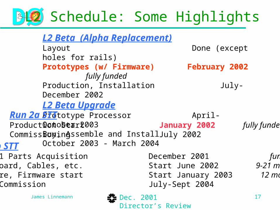
L2 Beta (Alpha Replacement)Layout Done (except holes for rails)Prototypes (w/ Firmware) February 2002 fully fundedProduction, Installation July-December 2002
L2 Beta UpgradePrototype Processor April-October 2003Buy, Assemble and Install October 2003 - March 2004
L2 Schedule: Some Highlights
Run 2a STTProduction Start January 2002 fully fundedCommissioning July 2002
Run 2b STTStage 1 Parts Acquisition December 2001 fundedEcho Board, Cables, etc. Start June 2002 9-21 mo. slackSoftware, Firmware start Start January 2003 12 mo. slack Test, Commission July-Sept 2004

James Linnemann 18
DD
Dec. 2001 Director’s Review
Conclusions
L2 Betas replacing Alpha Processors for Level 2 ProcessorsPrototypes being built to replace Alphas now
Add upgraded commercial processors for Run 2b
L2STT Staged Upgrade to utilize Run 2b Silicon Tracker
Reuse all boards from Run 2a STT Upgrade firmware, software
5 layers first (relatively small increment)
Full 6 layers installation limited by funding profile

James Linnemann 19
DD
Dec. 2001 Director’s Review
DØ Trigger Architecture Level 1
Calorimeter trigger
Fiber tracker trigger
Preshower (e/ trigger
Muon trigger
Level 2Silicon track trigger
Introduce Correlations, Refine Level 1 decision
Level 3Full event information
available
Farm of high-performance computing nodes

James Linnemann 20
DD
Dec. 2001 Director’s Review
Beta Cost Summary Motherboard: With contingency
Engineering (contributed in-kind) 166K
Prototypes (2+2) 18K
Production Boards (38 @ 2.4K) 91K
Motherboard Total 275K 346K
Single Board Computers ([email protected]) 130K 193K
Test Stands 38K 58K
Grand Total Betas 443K 596K (+35%)
Upgrade Processors
Engineering 20K 30K
Single Board Computers ([email protected]) 50K 64K
Adapters 3K 4K
Total Beta Upgrade Processors 72K 98K (+36%)

James Linnemann 21
DD
Dec. 2001 Director’s Review
L2 Beta (Alpha Replacement)Schematics - DoneLayout – Done (except holes for rails)Device driver API – November 2001Firmware – February 2002Prototypes – February 2002 Hardware Integration – March 2002System Integration – April 2002Begin production – July 2002Installation – November 2002 Engineering manpower:
Contributed by Universities
L2 Beta UpgradePrototype Processor May-October 2003Buy, Assemble and Install October 2003 to January 2004
Beta Schedule Summary

James Linnemann 22
DD
Dec. 2001 Director’s Review
L2STT Cost SummaryBaseline Upgrade (6 layers) With contingency
Extra Boards
20 STC, 8 TFC, 20 VTM
286K
Link Echo Board (new) 48K
STC Firmware 34K
New Backplane 15K
Cabling 19K
Baseline Total 402K 593K (+48%)
Stage I: 5 layers
Extra Boards (6 STC) 41K
STC Firmware 34K
Cables 6K
Total for 5 layers 81K 129K (+59%)

James Linnemann 23
DD
Dec. 2001 Director’s Review
STT Schedule Summary
Run 2a STTProduction Start January 2002 Run 2b should be at same timeCommissioning July 2002
Run 2b STTStage 1 Parts Acquisition December 2001Link Echo Board Start June 2002Backplane; Cables etc. start June 2002 about 1 year slackSoftware, Firmware start Jan 2003 about 6-8 months slackTest, Commission July-Sept 2004

James Linnemann 24
DD
Dec. 2001 Director’s Review
No Upgrade: 4 layers
Use only Run 2A STT hardwareonly instrument layers 0,2,4,5
Drop layers 1,3

James Linnemann 25
DD
Dec. 2001 Director’s Review
Staged Upgrade: 5 layers first
Use Run 2A STT + 6 STCinstrument layers 0,1,2,3,5

James Linnemann 26
DD
Dec. 2001 Director’s Review
Comparison of old, new SMT
Radii in cmLayer 2A 2B
0 21 3 3.52 5 6.13 7 9.54 9.5 12.75 15.5

James Linnemann 27
DD
Dec. 2001 Director’s Review
Acceptance
>98% of all tracks with b·2 mm and pT>1.5 GeV are contained in one 30o sector
b acc
0 97.0%
1 mm 98.5%
2 mm 99.5%

James Linnemann 28
DD
Dec. 2001 Director’s Review
Sample run 2b Trigger rates 5x1032 cm-2s-1, assuming no trigger upgrades High pT trigger menu exceeds available bandwidth
Trigger Physics Level 1 rate
(kHz)
EM tower > 10 GeV
We 5
2 Tracks (>10 & 5 GeV) +isolation + EM>2 GeV
H+- 10
2 Had+EM towers, sum > 4 GeV
ZHbb 2

James Linnemann 29
DD
Dec. 2001 Director’s Review
Calorimeter Trigger Upgrade Rate improvements from cluster thresholds vs. tower
thresholds
Single jet bbZH
3

James Linnemann 30
DD
Dec. 2001 Director’s Review
Conclusions Upgrades needed at level 1 to cope with:
need for increased rejection at level 1
Controlling rates even with multiple interactions
Triggering on correct beam crossing at 132 ns
Since last PAC meeting, extensive study of triggering options has been completed, resulting in a conceptual design for calorimeter and tracking upgradesScope has been limited due to constraints in schedule, manpower, and costs
Design offer considerable flexibility to deal with unanticipated physics requirements
We are ready to begin the detailed design and assemble the project
We request Stage 1 approval for the trigger upgrades

James Linnemann 31
DD
Dec. 2001 Director’s Review
Beta Software Issues High level software unchanged (identical user interface) However, alpha is more difficult to support than beta
Separate platform, and not supported by d0 environment
Very painful to support L2SIM if need for bit-by-bit verification
Supporting two platforms requires scarce high-level talentCould run mixed system, say alphas as administrators, to help
At very least need enough betas for all workers
Interrupt processing (max performance) exceptionally complex in alphaSimpler in beta
May not need in beta: trade CPU speed for software sophistication
Advantages to change drivers from process space to kernel spaceMuch harder in alpha
Much less community support for alpha
Example: active development for Linux Pentium process schedulerMay allow override of kernel much more simply than we could on alpha

James Linnemann 32
DD
Dec. 2001 Director’s Review
L2 Alpha BoardL2 Alpha BoardCommissioningCommissioning
• First Production2/2 pre-production work7/24 production came up (~9 months effort
UIC/UM/FNAL)– Most: multiple vias fixed and a
BGA replaced
– 17 abandoned• Broken CIA BGA not
replaceable (center of board)
– DMA patches (wires, pin lifting) performed
– PIO to Alpha not working (firmware)Aug/Sept
• concentrate on 1 Alpha/crate
Today’s score
6 up; 3 down (2 in ICU)
But 2 are pre-pro!6/7 “good” production boards are fragile

James Linnemann 33
DD
Dec. 2001 Director’s Review
baseline 1st year "minimum" min commissionTest Stand Crate 1 2 2 2 2 "global"Test Stand Crate 2 3 3 3 3 "multiprocessor"Test Stand Crate 3 2 2 0 0 2nd preprocessor testTest Stand Crate 4 0 0 0 0 data source uses prototypesGlobal 2 2 2 2Cal 4 4 4 0 OctPS 3 3 2 0 Sept?CTT 4 2 2 0 min is no stt; L1 in Sept?Mu 4 4 2 2 one crate; L1 in Junetotal 24 22 17 9 imaginable partial production
spare/extra power 14 16 21 2938 38 38 38
pre-production 2 2 2 2 as good as final cardsspare parts 10 10 10 10 but some needed by CDF tooold prototypes 2 2 2 2 useable for testing
We don't have enough parts to build the system twice.Could build all baseline workers twice
Administrators:test stand 3real system 6
total admin 9 9 7 4workers 15 13 10 5
How many Alphas?15 + test stand in 2001
•Need 15 for nominal system (+7 for test stand)
Min. Commissioning~ 9 boards

James Linnemann 34
DD
Dec. 2001 Director’s Review
Where do we put our Alphas?Staging; rotating tests
Aug-Sept (6 to 10 s) 1 Maryland 2 Test Stand/UIC 2 Global 2 Mu/Cal (turns?)
3 in dry dock
Oct (6 to20 s) 2 Test stand 2 Global 2-4 Mu 2-4 Cal 2-5 CTT,PS
1-4 UIC/Test Stand

James Linnemann 35
DD
Dec. 2001 Director’s Review
DMA/PIO
ECL drivers 500 MHz SBC
VME Interface
L2 Alpha Board
Biggest difficulties inSBC section of board
Mfg. ProblemsObsolete partsDebugging difficulty
Separate SBC and IO

James Linnemann 36
DD
Dec. 2001 Director’s Review
L2eta people:Bob Hirosky: UVa (Management, specs., device software Alpha transparency)Pierre Petroff, Philippe Cros, Bernard Lavigne: ORSAY(Management, engineering, 9U board production, prototype$)Drew Baden: UMD (Functional reqs., 1st round designs)
-Minimize exposure to SBC difficulties-Remove dependence on short lifetime products-Maintain compatibility w/ Alpha
B. Hirosky 10/17/00
‘L2ßeta’ CPU Concept Commercial6U CPUCardW/ UII on board
FPGAMBUS P I/O + DMAECL Latch Driver
MBUSStraight pass to VME
Latches + ECL Drivers
Cable to PMC/PCI
L2eta “group” formed in Jan 2001
Proposed Oct 2000 Baden/Hirosky

James Linnemann 37
DD
Dec. 2001 Director’s Review
I !like Ike!

James Linnemann 38
DD
Dec. 2001 Director’s Review
L2 Alpha BoardL2 Alpha BoardCommissioningCommissioning
•Second Production ( 2 samples ):•DMA fixes incorporated in layout
•Moved CIA BGA to a socket
–Risky, but can’t replace this BGA if it fails
•new supplier for raw boards
•better assembly (failures diagnosed; site visits)
–DØ pre-production at FNAL – no prompt
–UM board up/down CIA SOCKET PROBLEMS
–11 to follow: earliest mid-SeptemberProbable
decisi
on:
Drop sock
et, ris
k
Mountin
g CIA

James Linnemann 39
DD
Dec. 2001 Director’s Review
6U boardCompact PCI
9U board64 bit
<2MHzVME
FPGA
EC
L D
rive
rs
128 bits~20 MHzMBus
32 bits66 MHz (max)Local bus64 bits
33 MHzPCI
J1
J2
J3
J5
J4
PLX9656
UII
Dri
vers
Dri
vers
Clk(s)/roms
IDE
L2eta: 933MHz CPU; 64b 66MHz PCI
SPY

James Linnemann 40
DD
Dec. 2001 Director’s Review
SBC •Single/Dual PIII up to 933MHz•64-bit, 66MHz PCI•Mech. shock tolerance 50g for transit (immune to ‘Eisenhower effect’?)

James Linnemann 41
DD
Dec. 2001 Director’s Review
PLX9656
ECL
Secondary PCI BUS
J1
UII PIO DMA TSI
pcidev
API
HardwareInterface
Tundra
UIIB
J2
J3
PCI Front End64bit Master/Target
Add-on Bus
MDusAD/DA
VMEnode
FIFOsMBus
A/D + Control
Bridgedevice
Scalernode
Add-onBus Interface
Linux
-software compatibility!-programmer conservation
PLX CFG ROM
Xilinx FPGA/Verilog

James Linnemann 42
DD
Dec. 2001 Director’s Review
mb_clk_ingmb_clk_inpci_clk_ingpci_clk_in
alen_bigendn_blastbreqi
n_ads
n_dendmpaf_eotdp<3..0>
breqon_bterm
lad<31..0>n_lbe<3..0>lholdlholda
n_readyn_waitn_linto
n_lw_rn_lserr
n_dt_r
n_ccslclkn_linti
n_dack<1..0>n_dreq<1..0>
n_lb_resetuseri_llockiusero_llockopmereq
mba<31..0>mod_done<18..0>ev_loaded<3..0>n_bossreq
bossgrinn_bossoutbossgrout
n_dstroben_bossin
doneoutn_ddoneoutn_rd_wrn_startload
n_bufout1n_bufout0fifoemptyin
n_bufin1n_bufin0
n_ddonein
n_resetoutn_mbmastern_crmaster
n_fifoemptyoutn_resetin
n_mbenn_mbdatdirn_mbadddir
mbd<127..0>
vbddonel2_answer_readyext_tsi_int_reqj2_resv_out<7..0>
n_ga<4..0>test_out<3..0>
j2_resv_in<7..0>n_gap
tsi_out<31..0>
vbd_start_req
XCV405E
LOCAL BUS INTERFACE
Address decoder
State machine
TSI Block
TSI registers
State machine
Address decoder
State machine
MAGIC BUS
PIO Block
PIO registers
State machine
Address translator
Add mapper
Add translator
fifo_fullfifo_emptydma_accessecl_access
pci_accessmb_access
plx_accessvme_access
vme_activity
n_vme_rst_inn_sw_rst_offn_sw_rst_on
n_vme_rst_out
n_led_reset
test_pt<31..0>TEST POINTS
Rst & Display & Clock
Reset management
Display management
Clock management

James Linnemann 43
DD
Dec. 2001 Director’s Review
LOCAL BUS INTERFACE
Address decoder
State machine
PCI In Address Register
32
PCI Out Address Register
32ale
n_bigendn_blastbreqi
n_ads
n_dendmpaf_eotdp<3..0>
breqon_bterm
lad<31..0>
n_lbe<3..0>lholdlholda
n_readyn_waitn_linto
n_lw_rn_lserr
n_dt_r
n_ccslclkn_linti
n_dack<1..0>n_dreq<1..0>
n_lb_resetuseri_llockiusero_llockopmereq
pci_en_wr_mem_1
pci_ en_rd_mem_1
pci_ en_buf_mem_1
pci_ en_buf_mem_n
CombinatorialLogics
pci_ en_wr
pci_ en_rd
int_pci_mb
int_mb_pci
dma_pci_mb
dma_pci_mb
data_in<31..0>
data_out<31..0>
pci_add_out<31..0>
pci_add_in<31..0>

James Linnemann 44
DD
Dec. 2001 Director’s Review
Address decoder
State machine
32
32
mb_en_wr_mem_1
mb_en_rd_mem_1
mb_en_buf_mem_1
mb_en_buf_mem_n
CombinatorialLogics
mb_en_wr
mb_en_rd
int_pci_mb
int_mb_pci
dma_pci_mb
dma_pci_mb
MAGIC BUS INTERFACE
mod_done<18..0>ev_loaded<3..0>n_bossreq
bossgrinn_bossoutbossgrout
n_dstroben_bossin
doneoutn_ddoneoutn_rd_wrn_startload
n_bufout1n_bufout0fifoemptyin
n_bufin1n_bufin0
n_ddonein
n_resetoutn_mbmastern_crmaster
n_fifoemptyoutn_resetin
n_mbenn_mbdatdirn_mbadddir
mbd<127..0>
Magic Bus In Address Register
Magic Bus Out Address Register
mb_add_in<31..0>
data_out<127..0>
mba<31..0>
data_in<127..0>
mb_add_out<31..0>

James Linnemann 45
DD
Dec. 2001 Director’s Review
Production/Assembly
Assembly by Thomson (Thales) of France• produce PCB (subcontract)• assemble components• component acquisition under study• design/manufacture of mechanical components
• rails for 6U card• stiffeners for 9U card• front panel (ORSAY design)(Mech. drawings in early December)
• electrical testing (JTAG scans)•Xilinx / PLX / UII support interface

James Linnemann 46
DD
Dec. 2001 Director’s Review
Cost to build L2eta system
9U PCB + Mech. $1200
9U Components $1050
9U Assembly $200
9U Total $2450
SBC $3000
Production prototypes (2) $12,500
30 boards ~$165,000
~$5450/board

James Linnemann 47
DD
Dec. 2001 Director’s Review
number of STCs/TFCs
STT J3 backplane
CPU
VBD
TFC
STC
STC
STC
STC
STC
FRC
STC
STC
STC
STC
TFC
1 2 3 4 5 6 7 8 9 10 11 12 13 14 15 16 17 18 19 20 21
modified J3 backplane
CPU
VBD
TFC
STC
STC
STC
STC
STC
STC
STC
STC
STC
FRC
STC
STC
STC
STC
STC
STC
STC
TFC
1 2 3 4 5 6 7 8 9 10 11 12 13 14 15 16 17 18 19 20 21
14 TFC/STC slots/crate
2 TFC slots, 16 TFC/STC slots/crate

James Linnemann 48
DD
Dec. 2001 Director’s Review
FRC outputsmain logic
L3 buffer control
link tx
SCL receiver
max 15 LVDS
out(1 each for STC/TFC)

James Linnemann 49
DD
Dec. 2001 Director’s Review
Geometry 1 6 layers rmin = 15 mm layer 0: 128/256 strips 44 fibers/crate 11 STCs
layer HDI/
0 12 6
1 18 6
2 12 4
3 18 4
4 24 4
5 30 4
b 0 1 mm 2 mm
pT = 100.0% 99.2% 97.3%
pT = 1.5 GeV 99.0% 98.6% 97.2%
b 0 1 mm 2 mm
pT = 91.8% 90.3% 83.5%
pT = 1.5 GeV 91.1% 89.2% 83.2%

James Linnemann 50
DD
Dec. 2001 Director’s Review
Geometry 2 6 layers rmin = 20 mm layer 0: 256 strips 44 fibers/crate 11 STCs
layer HDI/
0 12 6
1 18 6
2 12 4
3 18 4
4 24 4
5 30 4
b 0 1 mm 2 mm
pT = 99.4% 98.2% 96.3%
pT = 1.5 GeV 98.3% 97.7% 96.0%

James Linnemann 51
DD
Dec. 2001 Director’s Review
Geometry 3 6 layers rmin = 19 mm layer 0: 256 strips layer 1: 384 strips 40 fibers/crate 10 STCs
layer HDI/
0 12 6
1 12 6
2 12 4
3 18 4
4 24 4
5 30 4
b 0 1 mm 2 mm
pT = 100% 100% 100%
pT = 1.5 GeV 100% 100% 100%

James Linnemann 52
DD
Dec. 2001 Director’s Review
Does it work?
crate 6 1
sectors 12&1 1 1&2 2 2&3
fibers 14 8 10 8 14
STCs 4 2 3 1* 4
* 2 fibers to other STCs
9 STCs 8 STCs
NO

James Linnemann 53
DD
Dec. 2001 Director’s Review
18 Sectors
b 0 1 mm 2 mm
pT = 100% 100% 100%
pT = 1.5 GeV 100% 100% 100%
crate 6 1 sectors 18 & 1 1 & 2 2 2 & 3 3 & 4 HDIs/side 14 8 10 8 14 fibers 14 8 10 8 14 STCs 4 2 3 2 4
Crate 1
CP
U
VB
D
term
ina
tors
TF
C-C
TF
C-B
S T C
S T C
S T C
S T C
S T C
FR
C
S T C
S T C
S T C
S T C
S T C
S T C
TF
C-A
term
ina
tors
1 2 3 4 5 6 7 8 9 10 11 12 13 14 15 16 17 18 19 20 21 Crate 6
CP
U
VB
D
term
ina
tors
TF
C
TF
C
S T C
S T C
S T C
S T C
S T C
FR
C
S T C
S T C
S T C
S T C
S T C
S T C
TF
C
term
ina
tors
1 2 3 4 5 6 7 8 9 10 11 12 13 14 15 16 17 18 19 20 21
6 or 7 STC inputs OK

James Linnemann 54
DD
Dec. 2001 Director’s Review
Geometry 4 6 layers rmin = 15 mm layer 0: 384 strips (pinwheel) layer 3,5: 80 m or 768 strips 34 fibers/crate 9 STCs
layer HDI/
0 6 6
1 12 6
2 12 4
3 12 4
4 24 4
5 24 4
b 0 1 mm 2 mm
pT = 100% 100% 98.4%
pT = 1.5 GeV 100% 99.6% 98.1%
OK

James Linnemann 55
DD
Dec. 2001 Director’s Review
Pinwheel Option Alayer HDI fiberscra
teSTCscra
te
0 6 12 6
1 12 6 6
2 12 4 4
3 18 4 6
4 24 4 8
5 30 4 10
total 40 10
not OK with 12 or 18 sectors
layer 0 sensors must go to 3 (12 sectors) or 4 (18 sectors) TFCs else acceptance too low

James Linnemann 56
DD
Dec. 2001 Director’s Review
Pinwheel Option B
layer HDI fiberscrate
STCscrate
0 8 12 8
1 12 6 6
2 12 4 4
3 18 4 6
4 24 4 8
5 30 4 10
total 42 11
don’t know yet

James Linnemann 57
DD
Dec. 2001 Director’s Review
Castellated Geometry Option
layer HDI fiberscrate
STCscrate
0 12 12 (6) 12 (6)
1 12 6 6
2 12 4 4
3 18 4 6
4 24 4 8
5 30 4 10
total 46 (40) 12 (10)
similar to geometry 3 18 sectors OK?

James Linnemann 58
DD
Dec. 2001 Director’s Review
Other Issues increase in layers/HDIs per sector
need bigger tables in TFC memory
more roads/layersmore/upgraded TFCs
higher silicon occupancymodify fit algorithm
new stage to select patterns?
determination of z-vertexbenefits (?)
dedicated hardware in STT or in L2CTT

James Linnemann 59
DD
Dec. 2001 Director’s Review
Summary of Constraints max 15 STC+TFC
more than 14 STC+TFC require new backplane
max 8 STC inputs per TFCaffects sector definitions
20-degree sectors (3 TFC/crate)
resources in TFC daughterboardLUT memory
processing power

James Linnemann 60
DD
Dec. 2001 Director’s Review
As of yesterday… layers 2-5
640 strips, 60 m, 12-18-24-30
layer 1 384 strips, 12 , 6 HDI/
layer 0rmin = 18 mm
12 HDI/pinwheel
A: 384 strips, 6 B: 256 strips, 8
castellated geometry?

James Linnemann 61
DD
Dec. 2001 Director’s Review
6U boardCompact PCI
9U board64 bit
<2MHzVME
FPGA
EC
L D
rive
rs
128 bits~20 MHzMBus
32 bits66 MHz (max)Local bus64 bits
33 MHzPCI
J1
J2
J3
J5
J4
PLX9656
UII
Dri
vers
Dri
vers
Clk(s)/roms
•PIII Compact PCI card
•9U card with “custom” devices (3 BGA’s)
–Universe Chip VME interface
–commercial 64-bit PCI interface chip
–MBus and other logic in FPGA
Basic Idea