Embed Size (px)
Citation preview

THE DIGITAL THREAD & SPDM
Jayendra Ganguli
Associate Director, Digital Thread Solution Architecture
Raytheon Technologies

NAFEMS.org/SystemsThinking The Digital Thread and SPDM RevolutionInSimulation.org/SystemsThinking
The story so far ... (from previous webinar in this series)

NAFEMS.org/SystemsThinking The Digital Thread and SPDM RevolutionInSimulation.org/SystemsThinking
• Are Engineers “talking” via models?
• Unmodeled and undesired
interactions leading to emergent
behaviors
Who spun the thread? When did the thread break?
Source: Paul Eremenko, Adaptive Make: DARPA Manufacturing Portfolio OverviewHarvard Business Review: https://hbr.org/2007/11/are-your-engineers-talking-to-one-another-when-they-should
Image Source: DARPA
http://www.terpconnect.umd.edu/~austin/ense622.d/lecture-resources/CSER2013-DARPA-Keynote-Eremenko.pdf

NAFEMS.org/SystemsThinking The Digital Thread and SPDM RevolutionInSimulation.org/SystemsThinking
Source: Paul Eremenko, Adaptive Make: DARPA Manufacturing Portfolio OverviewHarvard Business Review: https://hbr.org/2007/11/are-your-engineers-talking-to-one-another-when-they-should
• Are Engineers “talking” via models?
• Unmodeled and undesired
interactions leading to emergent
behaviors
“ the engine was divided into eight subsystems,
each of which was further decomposed into five
to ten components, for a total of 54 engine
components. Typical for such projects, the
development organization was correspondingly
structured into 54 cross-functional design teams
responsible for each component, plus six
integration teams responsible for managing
engine-level requirements ”
Who spun the thread? When did the thread break?
Image Source: DARPA
http://www.terpconnect.umd.edu/~austin/ense622.d/lecture-resources/CSER2013-DARPA-Keynote-Eremenko.pdf

NAFEMS.org/SystemsThinking The Digital Thread and SPDM RevolutionInSimulation.org/SystemsThinking
• Are Engineers “talking” via models?
• Unmodeled and undesired
interactions leading to emergent
behaviors
“ the engine was divided into eight subsystems,
each of which was further decomposed into five
to ten components, for a total of 54 engine
components. Typical for such projects, the
development organization was correspondingly
structured into 54 cross-functional design teams
responsible for each component, plus six
integration teams responsible for managing
engine-level requirements ”
Can your Simulation LifeCycle Manager keep up with the evolving
System Model and corresponding change in interfaces?
Who spun the thread? When did the thread break?
Source: Paul Eremenko, Adaptive Make: DARPA Manufacturing Portfolio OverviewHarvard Business Review: https://hbr.org/2007/11/are-your-engineers-talking-to-one-another-when-they-should
Image Source: DARPA
http://www.terpconnect.umd.edu/~austin/ense622.d/lecture-resources/CSER2013-DARPA-Keynote-Eremenko.pdf

NAFEMS.org/SystemsThinking The Digital Thread and SPDM RevolutionInSimulation.org/SystemsThinking
• The “single source of truth” isn’t in one place. It’s distributed
geographically, and even within one chip. And it’s constantly
changing.
• Model abstractions and hierarchy across multi-disciplinary multi-
physics domains. These abstractions don’t always match
• It’s always evolving … it’s not static. Anything that you have stored in
a “file” quickly becomes redundant. There is a reason some PLM
vendors have said “no more files.” (Hello, Technical Data “Package”!)
• Practical Current Challenge the industry faces:
o The IT architecture of traditional SLM rides on a old PLM chassis.
This approach will need a rethink. (The interplay between the
System Model and System Architecture Model)
Image Source: Paul Eremenko, Adaptive Make: DARPA Manufacturing Portfolio OverviewChristopher Davey:Ford.Automotive Software Systems Complexity: Challenges and Opportunities-INCOSE 2013
RFLP-Models, Scenario and Results & more … in that hairballWhat contributes to the complexity that a Lifecycle Manager needs to track and manage? What are the sources of complexity? What is the nature of the complexity?

NAFEMS.org/SystemsThinking The Digital Thread and SPDM RevolutionInSimulation.org/SystemsThinking
Challenges here and Now!
• Increased dependency on
Cloud
• IP issues
• Fidelity and rate of
Simulation data exchange
• Digital twins and Physics:
How fast can you merge
physics models and keep
them consistent with Learnt
models?
• Fusion of Physics, sensor
data, and edge analytics
models and their
representation in simulation
Image Source: http://gpdisonline.com/wp-content/uploads/past-presentations/SE_60_Airbus-AdrianMurton-MoSSEC.pdf
The distributed nature of Simulation Data
Engineering data management for performance developmentToyota Motor Europe’s case study
Ernesto Mottola, PhD
Senior Manager, Model Based Development
Toyota Motor Europe R&D, Vehicle Performance Engineering

NAFEMS.org/SystemsThinking The Digital Thread and SPDM RevolutionInSimulation.org/SystemsThinking
The perspective of automotive industry
All the traditional challenges…

NAFEMS.org/SystemsThinking The Digital Thread and SPDM RevolutionInSimulation.org/SystemsThinking
The perspective of automotive industry
All the traditional challenges…
Safety
Cost
Emissions
Comfort
Regulations
Customer
appealStyle
Quality
Production
Platform
commonisation
Lightweight

NAFEMS.org/SystemsThinking The Digital Thread and SPDM RevolutionInSimulation.org/SystemsThinking
…and a “once-in-a-century” shake-up from C.A.S.E.*
Toyota evolving from a car company to a mobility company(source: Toyota annual report 2018)
(*) C.A.S.E.ConnectedAutonomousSharedElectrified

NAFEMS.org/SystemsThinking The Digital Thread and SPDM RevolutionInSimulation.org/SystemsThinking
How systems thinking is developing
ISFuel econ.
Body
Chassis
E/G
D/T
Control
Body
NV
Ride
Control
Handling
Chassis
Drivability
Durability
Power
Train
Target
HiLS
Simulator
Customer
VPMVirtual Environment Real Test
Concept
PM
MBD* to realise a holistic vehicle/systems development approach through simulation
(*) MBD = Model Based Development
NAFEMS.org/SystemsThinking The Digital Thread and SPDM RevolutionInSimulation.org/SystemsThinking
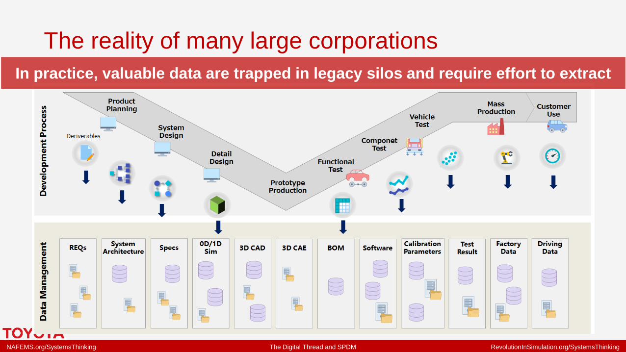
The reality of many large corporations
In practice, valuable data are trapped in legacy silos and require effort to extract

NAFEMS.org/SystemsThinking The Digital Thread and SPDM RevolutionInSimulation.org/SystemsThinking
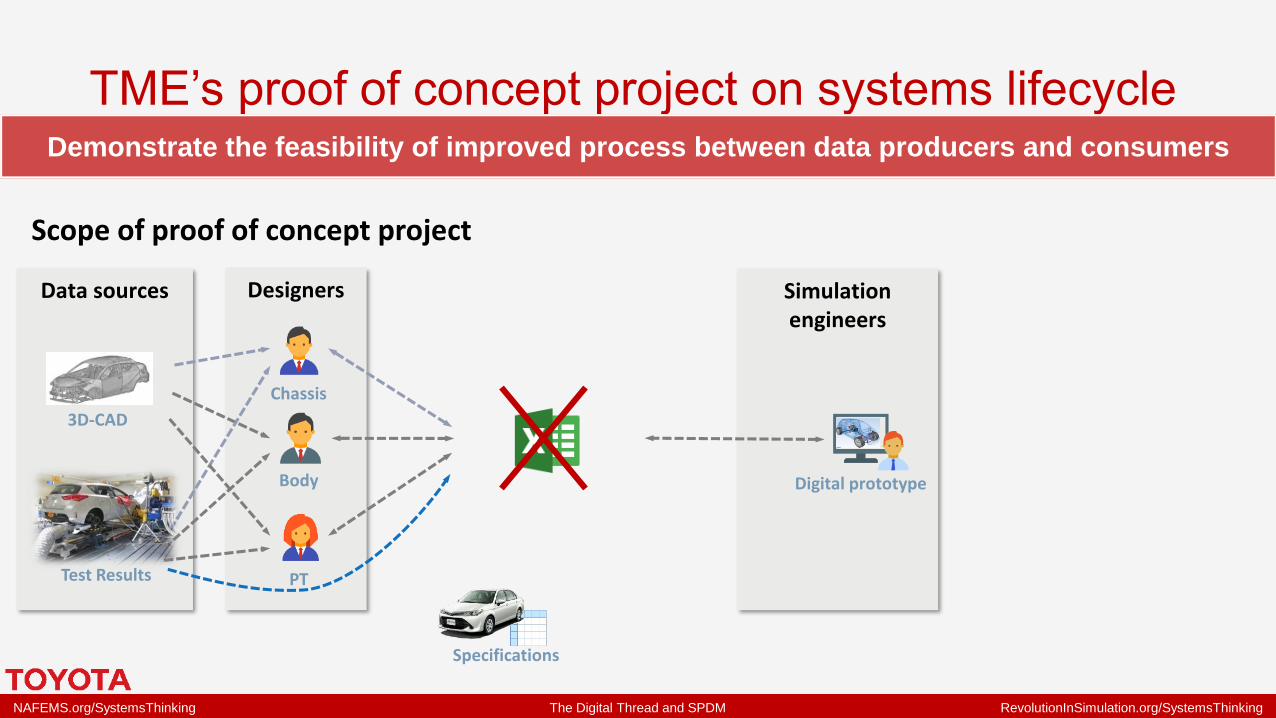
TME’s proof of concept project on systems lifecycleDemonstrate the feasibility of improved process between data producers and consumers
Data sources Designers Simulationengineers
3D-CAD
Test Results
Specifications
Chassis
Body
PT
Digital prototype
Scope of proof of concept project
NAFEMS.org/SystemsThinking The Digital Thread and SPDM RevolutionInSimulation.org/SystemsThinking
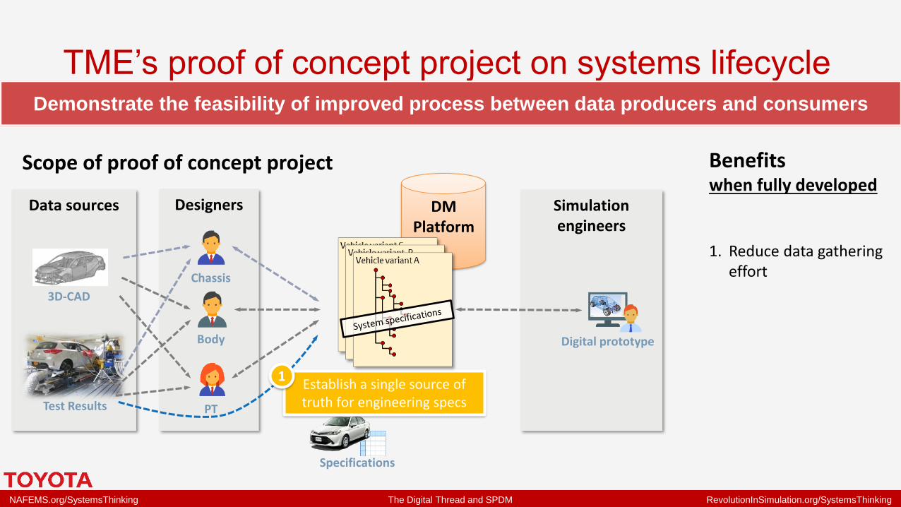
TME’s proof of concept project on systems lifecycleDemonstrate the feasibility of improved process between data producers and consumers
DMPlatform
Data sources Designers Simulationengineers
3D-CAD
Test Results
Specifications
Chassis
Body
PT
Digital prototype
Establish a single source of truth for engineering specs
1
Benefitswhen fully developed
1. Reduce data gathering effort
Scope of proof of concept project

NAFEMS.org/SystemsThinking The Digital Thread and SPDM RevolutionInSimulation.org/SystemsThinking
TME’s proof of concept project on systems lifecycleDemonstrate the feasibility of improved process between data producers and consumers
DMPlatform
Data sources Designers Simulationengineers
3D-CAD
Test Results
Specifications
Chassis
Body
PT
Digital prototype
Enable data re-use
2
Suppliers
Purchasing
…
Establish a single source of truth for engineering specs
1
Benefitswhen fully developed
1. Reduce data gathering effort
2. Capitalise past knowledge
Scope of proof of concept project

NAFEMS.org/SystemsThinking The Digital Thread and SPDM RevolutionInSimulation.org/SystemsThinking
TME’s proof of concept project on systems lifecycleDemonstrate the feasibility of improved process between data producers and consumers
DMPlatform
Data sources Designers Simulationengineers
3D-CAD
Test Results
Specifications
Chassis
Body
PT
Digital prototype
Increase speed and quality of simulation model making by
automated process3
Enable data re-use
2
Suppliers
Purchasing
…
Establish a single source of truth for engineering specs
1
Benefitswhen fully developed
1. Reduce data gathering effort
2. Capitalise past knowledge
3. Enable faster simulation studies, with higher quality data
Scope of proof of concept project

NAFEMS.org/SystemsThinking The Digital Thread and SPDM RevolutionInSimulation.org/SystemsThinking
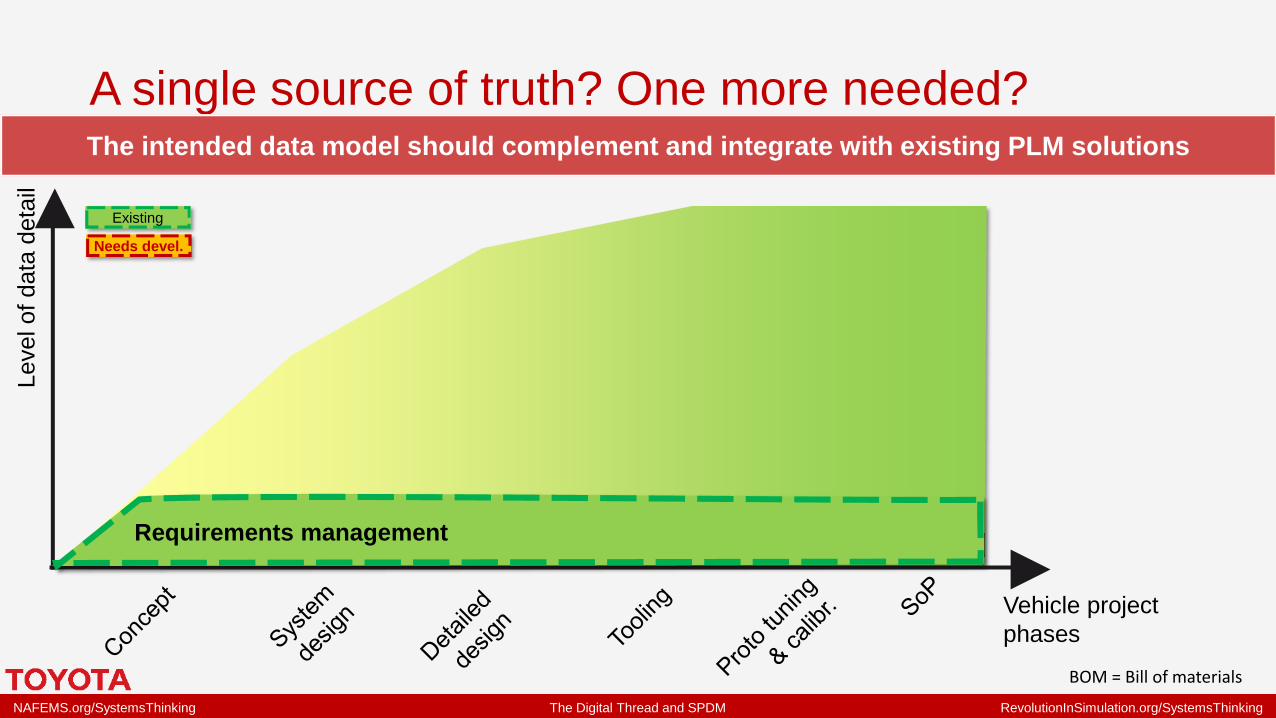
A single source of truth? One more needed?The intended data model should complement and integrate with existing PLM solutions
BOM = Bill of materials
Vehicle project
phases
Level of data
deta
il
Existing
Needs devel.
NAFEMS.org/SystemsThinking The Digital Thread and SPDM RevolutionInSimulation.org/SystemsThinking
A single source of truth? One more needed?The intended data model should complement and integrate with existing PLM solutions
BOM = Bill of materials
Vehicle project
phases
Level of data
deta
il
Requirements management
Existing
Needs devel.

NAFEMS.org/SystemsThinking The Digital Thread and SPDM RevolutionInSimulation.org/SystemsThinking
A single source of truth? One more needed?The intended data model should complement and integrate with existing PLM solutions
BOM = Bill of materials
Vehicle project
phases
Level of data
deta
il
“Traditional PLM”
3D CAD
eBOM (detailed product structure)
3D Structural
simulation
& SPDM
Requirements management
System performance
Simulation
Existing
Needs devel.

NAFEMS.org/SystemsThinking The Digital Thread and SPDM RevolutionInSimulation.org/SystemsThinking
A single source of truth? One more needed?The intended data model should complement and integrate with existing PLM solutions
BOM = Bill of materials
System
specifications
Vehicle project
phases
Level of data
deta
il
“Traditional PLM”
3D CAD
eBOM (detailed product structure)
3D Structural
simulation
& SPDM
Requirements management
System performance
Simulation
Requirements for
managing engineering
specifications:
▪ Flexible product
structure & data
▪ Tool independent
process automation
▪ Data federation from
other sources
Existing
Needs devel.

NAFEMS.org/SystemsThinking The Digital Thread and SPDM RevolutionInSimulation.org/SystemsThinking
What are the characteristics of this data structure?A structure flexible enough to support current simulation tools and developing SE thinking
Vehicle variant CVehicle variant B
Vehicle variant A

NAFEMS.org/SystemsThinking The Digital Thread and SPDM RevolutionInSimulation.org/SystemsThinking
What are the characteristics of this data structure?A structure flexible enough to support current simulation tools and developing SE thinking
Vehicle variant CVehicle variant B
Vehicle variant A
TodayA container for all parameters required
by existing simulation models
Vehicle variant CVehicle variant B
Vehicle variant A
MBS models
Vehicle variant CVehicle variant B
Vehicle variant A
Vehicle variant CVehicle variant B
Vehicle variant A
Calc. sheets
Defined by…
Simple models

NAFEMS.org/SystemsThinking The Digital Thread and SPDM RevolutionInSimulation.org/SystemsThinking
What are the characteristics of this data structure?A structure flexible enough to support current simulation tools and developing SE thinking
TomorrowA system structure defined by more formal
methods → The data model for Systems Lifecycle Management
Technical breakdown structures
RFLP structures
SysML diagrams
Defined by…
Or:
Or:
Systems
Vehicle variant CVehicle variant B
Vehicle variant A
Require
mentsPart lists CAD DB
Other
DBs…
TodayA container for all parameters required
by existing simulation models
Vehicle variant CVehicle variant B
Vehicle variant A
MBS models
Vehicle variant CVehicle variant B
Vehicle variant A
Vehicle variant CVehicle variant B
Vehicle variant A
Calc. sheets
Defined by…
Simple models

NAFEMS.org/SystemsThinking The Digital Thread and SPDM RevolutionInSimulation.org/SystemsThinking
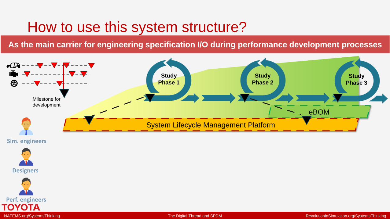
How to use this system structure?As the main carrier for engineering specification I/O during performance development processes
eBOM
System Lifecycle Management Platform
Study
Phase 1
Study
Phase 2Study
Phase 3
Sim. engineers
Designers
Perf. engineers
NAFEMS.org/SystemsThinking The Digital Thread and SPDM RevolutionInSimulation.org/SystemsThinking
How to use this system structure?As the main carrier for engineering specification I/O during performance development processes
eBOM
System Lifecycle Management Platform
Study
Phase 1
Study
Phase 2Study
Phase 3
Milestone for
development
Sim. engineers
Designers
Perf. engineers

NAFEMS.org/SystemsThinking The Digital Thread and SPDM RevolutionInSimulation.org/SystemsThinking
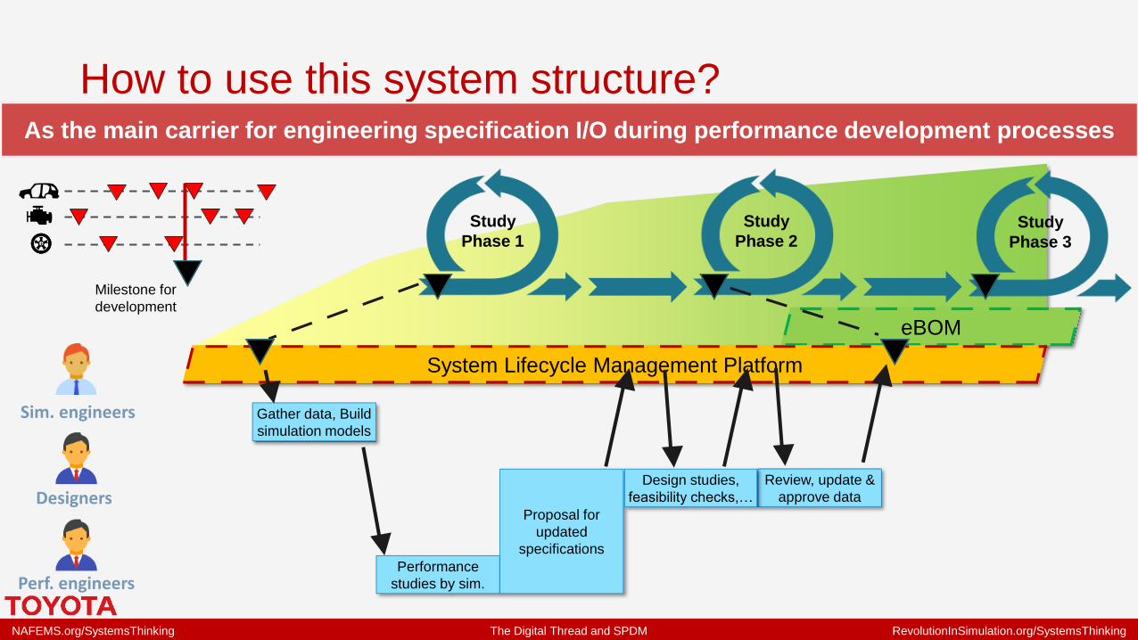
How to use this system structure?As the main carrier for engineering specification I/O during performance development processes
eBOM
System Lifecycle Management Platform
Study
Phase 1
Study
Phase 2Study
Phase 3
Milestone for
development
Gather data, Build
simulation models
Sim. engineers
Designers
Perf. engineers

NAFEMS.org/SystemsThinking The Digital Thread and SPDM RevolutionInSimulation.org/SystemsThinking
How to use this system structure?As the main carrier for engineering specification I/O during performance development processes
eBOM
System Lifecycle Management Platform
Study
Phase 1
Study
Phase 2Study
Phase 3
Milestone for
development
Gather data, Build
simulation models
Performance
studies by sim.
Proposal for
updated
specifications
Sim. engineers
Designers
Perf. engineers
NAFEMS.org/SystemsThinking The Digital Thread and SPDM RevolutionInSimulation.org/SystemsThinking
How to use this system structure?As the main carrier for engineering specification I/O during performance development processes
eBOM
System Lifecycle Management Platform
Study
Phase 1
Study
Phase 2Study
Phase 3
Milestone for
development
Gather data, Build
simulation models
Performance
studies by sim.
Proposal for
updated
specifications
Review, update &
approve data
Design studies,
feasibility checks,…
Sim. engineers
Designers
Perf. engineers
NAFEMS.org/SystemsThinking The Digital Thread and SPDM RevolutionInSimulation.org/SystemsThinking
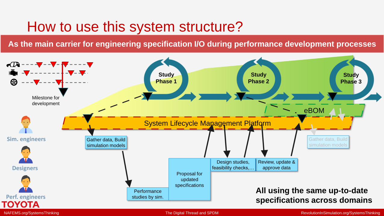
How to use this system structure?As the main carrier for engineering specification I/O during performance development processes
eBOM
System Lifecycle Management Platform
Study
Phase 1
Study
Phase 2Study
Phase 3
Milestone for
development
Gather data, Build
simulation models
Performance
studies by sim.
Proposal for
updated
specifications
Review, update &
approve data
Design studies,
feasibility checks,…
All using the same up-to-date
specifications across domains
Gather data, Build
simulation modelsSim. engineers
Designers
Perf. engineers

NAFEMS.org/SystemsThinking The Digital Thread and SPDM RevolutionInSimulation.org/SystemsThinking
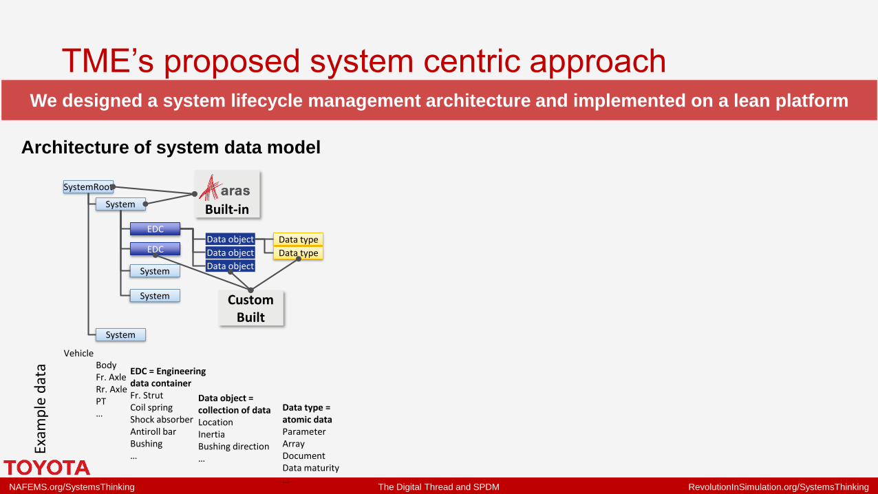
TME’s proposed system centric approachWe designed a system lifecycle management architecture and implemented on a lean platform
NAFEMS.org/SystemsThinking The Digital Thread and SPDM RevolutionInSimulation.org/SystemsThinking
Exam
ple
dat
a
SystemRoot
System
System
System
System
EDC
EDCData object
Data object
Data object
Data type
Data type
VehicleBodyFr. AxleRr. AxlePT…
EDC = Engineering data containerFr. StrutCoil springShock absorberAntiroll barBushing…
Data object = collection of dataLocationInertiaBushing direction…
Data type = atomic dataParameterArrayDocumentData maturity…
Built-in
Custom Built
We designed a system lifecycle management architecture and implemented on a lean platform
Architecture of system data model
TME’s proposed system centric approach

NAFEMS.org/SystemsThinking The Digital Thread and SPDM RevolutionInSimulation.org/SystemsThinking
Exam
ple
dat
a
SystemRoot
System
System
System
System
EDC
EDCData object
Data object
Data object
Data type
Data type
VehicleBodyFr. AxleRr. AxlePT…
EDC = Engineering data containerFr. StrutCoil springShock absorberAntiroll barBushing…
Data object = collection of dataLocationInertiaBushing direction…
Data type = atomic dataParameterArrayDocumentData maturity…
Built-in
Custom Built
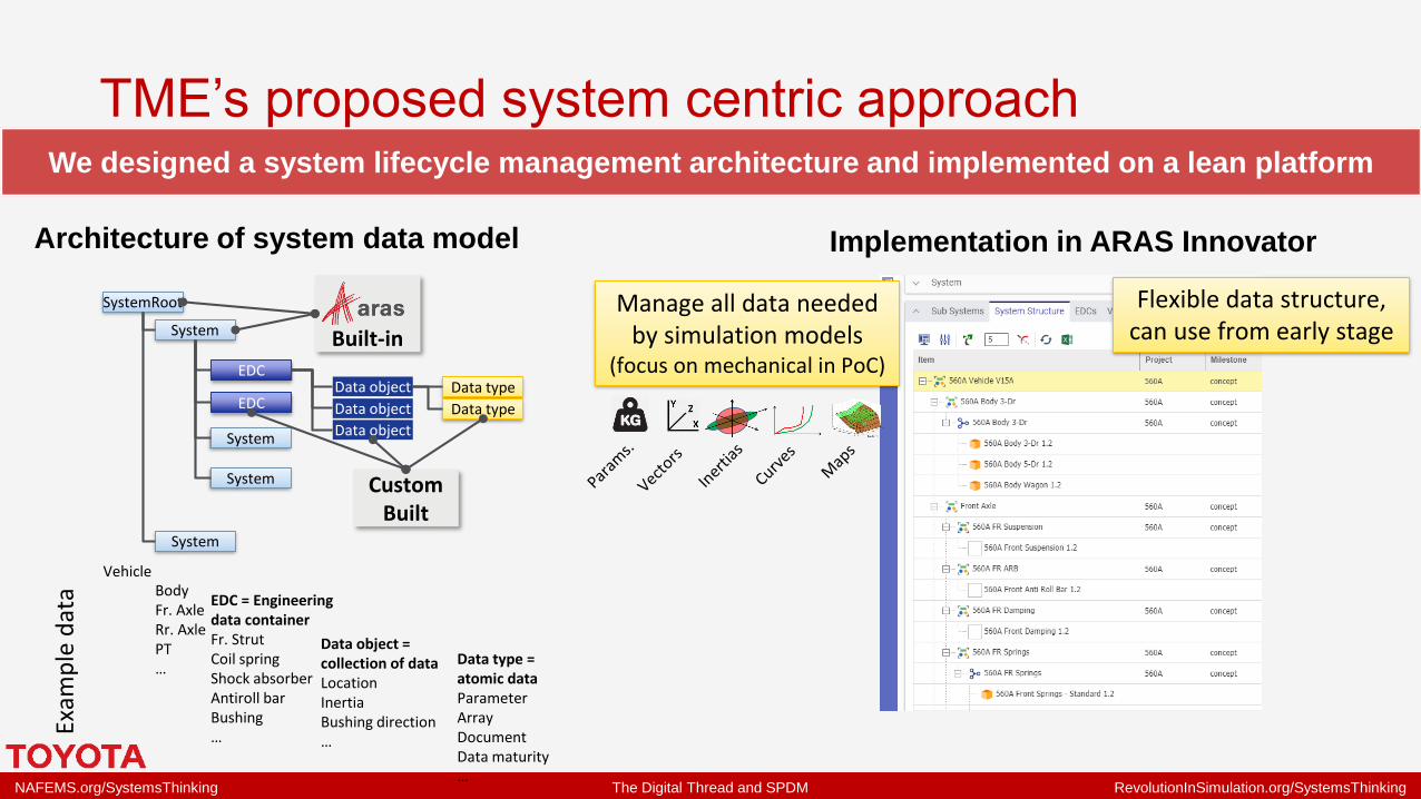
We designed a system lifecycle management architecture and implemented on a lean platform
Flexible data structure, can use from early stage
Architecture of system data model Implementation in ARAS Innovator
TME’s proposed system centric approach
NAFEMS.org/SystemsThinking The Digital Thread and SPDM RevolutionInSimulation.org/SystemsThinking
Exam
ple
dat
a
SystemRoot
System
System
System
System
EDC
EDCData object
Data object
Data object
Data type
Data type
VehicleBodyFr. AxleRr. AxlePT…
EDC = Engineering data containerFr. StrutCoil springShock absorberAntiroll barBushing…
Data object = collection of dataLocationInertiaBushing direction…
Data type = atomic dataParameterArrayDocumentData maturity…
Built-in
Custom Built
We designed a system lifecycle management architecture and implemented on a lean platform
Flexible data structure, can use from early stage
Manage all data needed by simulation models
(focus on mechanical in PoC)
Architecture of system data model Implementation in ARAS Innovator
TME’s proposed system centric approach
NAFEMS.org/SystemsThinking The Digital Thread and SPDM RevolutionInSimulation.org/SystemsThinking
Exam
ple
dat
a
SystemRoot
System
System
System
System
EDC
EDCData object
Data object
Data object
Data type
Data type
VehicleBodyFr. AxleRr. AxlePT…
EDC = Engineering data containerFr. StrutCoil springShock absorberAntiroll barBushing…
Data object = collection of dataLocationInertiaBushing direction…
Data type = atomic dataParameterArrayDocumentData maturity…
Built-in
Custom Built
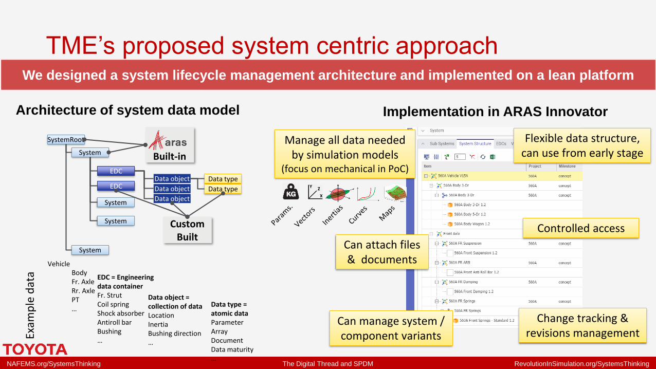
We designed a system lifecycle management architecture and implemented on a lean platform
Can manage system / component variants
Change tracking & revisions management
Controlled access
Flexible data structure, can use from early stage
Can attach files & documents
Manage all data needed by simulation models
(focus on mechanical in PoC)
Architecture of system data model Implementation in ARAS Innovator
TME’s proposed system centric approach
NAFEMS.org/SystemsThinking The Digital Thread and SPDM RevolutionInSimulation.org/SystemsThinking
Development of usability & acceptanceA user friendly GUI hides the complexity of the underlying database for easy I/O
NAFEMS.org/SystemsThinking The Digital Thread and SPDM RevolutionInSimulation.org/SystemsThinking
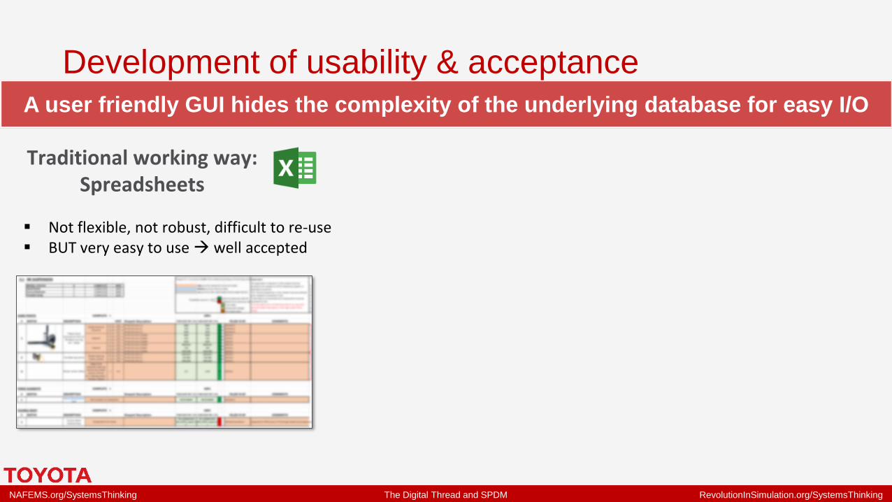
A user friendly GUI hides the complexity of the underlying database for easy I/O
Traditional working way:Spreadsheets
▪ Not flexible, not robust, difficult to re-use▪ BUT very easy to use → well accepted
Development of usability & acceptance
NAFEMS.org/SystemsThinking The Digital Thread and SPDM RevolutionInSimulation.org/SystemsThinking
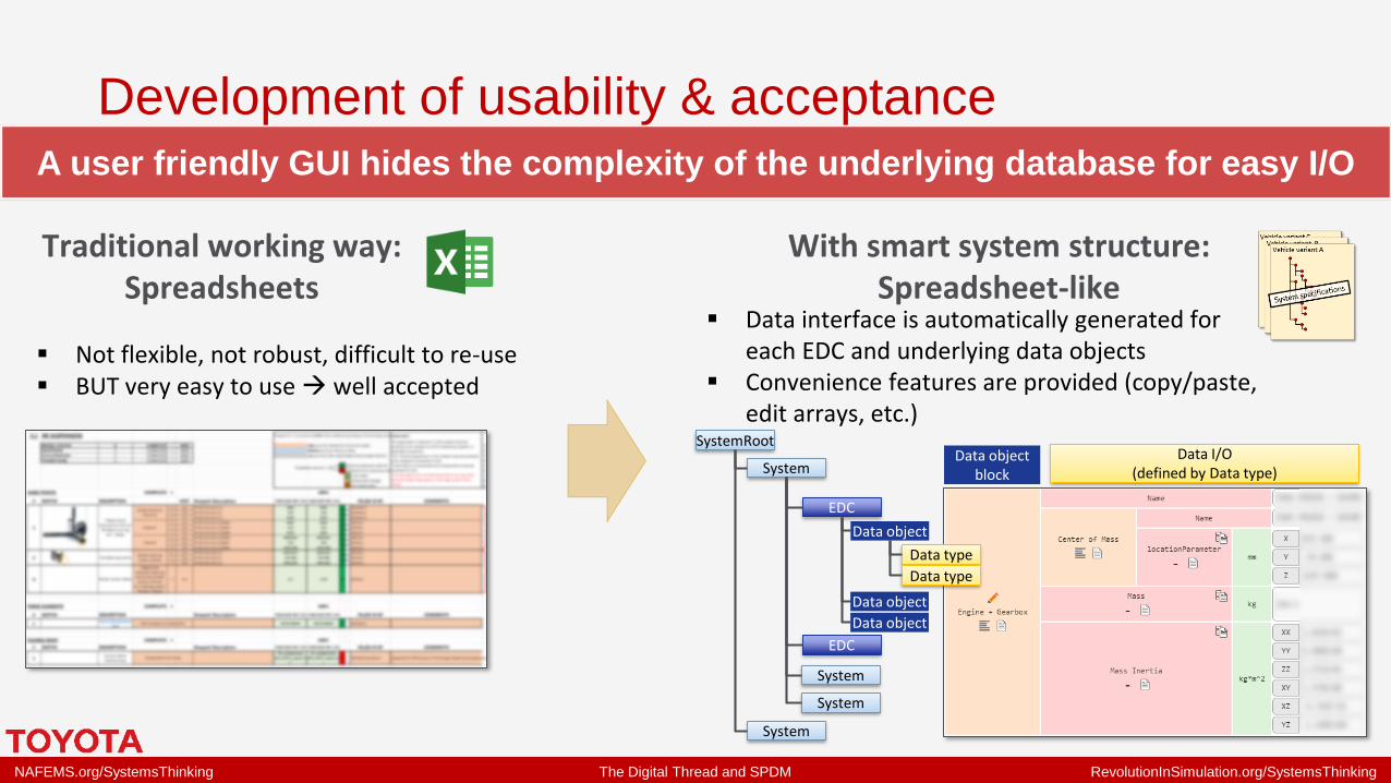
A user friendly GUI hides the complexity of the underlying database for easy I/O
Traditional working way:Spreadsheets
▪ Not flexible, not robust, difficult to re-use▪ BUT very easy to use → well accepted
With smart system structure:Spreadsheet-like
▪ Data interface is automatically generated for each EDC and underlying data objects
▪ Convenience features are provided (copy/paste, edit arrays, etc.)
Data object block
Data I/O(defined by Data type)
SystemRoot
System
System
System
System
EDC
EDC
Data object
Data object
Data object
Data type
Data type
Development of usability & acceptance

NAFEMS.org/SystemsThinking The Digital Thread and SPDM RevolutionInSimulation.org/SystemsThinking
Features for data re-use and capitalisationWe secured flexible data access and re-use → basis for value, enabler for data science!
NAFEMS.org/SystemsThinking The Digital Thread and SPDM RevolutionInSimulation.org/SystemsThinking
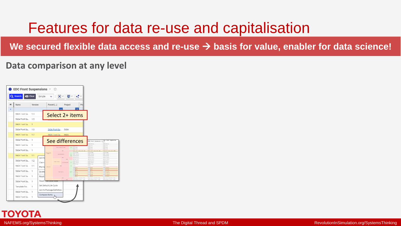
We secured flexible data access and re-use → basis for value, enabler for data science!
Data comparison at any level
Select 2+ items
See differences
Features for data re-use and capitalisation

NAFEMS.org/SystemsThinking The Digital Thread and SPDM RevolutionInSimulation.org/SystemsThinking
We secured flexible data access and re-use → basis for value, enabler for data science!
Data comparison at any level
Select 2+ items
See differences
Data re-use by flexible queries
Visual query builder
▪ Any object can be searched▪ Any related object data or property
can be used as search criteria
Example:Search all front suspension systems which knuckle has Z location at 1000-1200mm, belonging to 123A series, with trimmed body mass > 700 kg
Features for data re-use and capitalisation

NAFEMS.org/SystemsThinking The Digital Thread and SPDM RevolutionInSimulation.org/SystemsThinking
We secured flexible data access and re-use → basis for value, enabler for data science!
Various ways to access dataData comparison at any level
Select 2+ items
See differences
Data re-use by flexible queries
Visual query builder
▪ Any object can be searched▪ Any related object data or property
can be used as search criteria
Example:Search all front suspension systems which knuckle has Z location at 1000-1200mm, belonging to 123A series, with trimmed body mass > 700 kg
Native client =
web browserExport/Import
(via macro)
AML Console
SOAP
Http/AMLRest
Http/JSON
.Net
VB, C#,
Python, C++
Custom
connectors
Features for data re-use and capitalisation

NAFEMS.org/SystemsThinking The Digital Thread and SPDM RevolutionInSimulation.org/SystemsThinking
Process automationWith suitable data model in place, various (x-func.) processes can be automated with confidence
NAFEMS.org/SystemsThinking The Digital Thread and SPDM RevolutionInSimulation.org/SystemsThinking
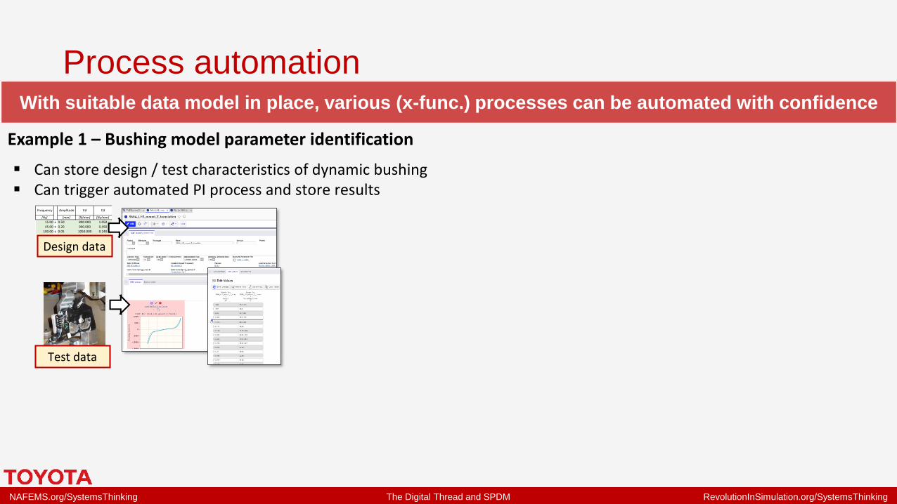
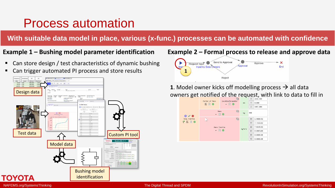
With suitable data model in place, various (x-func.) processes can be automated with confidence
Example 1 – Bushing model parameter identification
[Hz] [mm] [N/mm] [Ns/mm]
15.00 ± 0.50 800.000 1.050
45.00 ± 0.20 900.000 0.450
100.00 ± 0.05 1050.000 0.240
±
±
Frequency CdAmplitude Kd
Design data
Test data
▪ Can store design / test characteristics of dynamic bushing▪ Can trigger automated PI process and store results
Process automation

NAFEMS.org/SystemsThinking The Digital Thread and SPDM RevolutionInSimulation.org/SystemsThinking
With suitable data model in place, various (x-func.) processes can be automated with confidence
Example 1 – Bushing model parameter identification
[Hz] [mm] [N/mm] [Ns/mm]
15.00 ± 0.50 800.000 1.050
45.00 ± 0.20 900.000 0.450
100.00 ± 0.05 1050.000 0.240
±
±
Frequency CdAmplitude Kd
Design data
Test data
▪ Can store design / test characteristics of dynamic bushing▪ Can trigger automated PI process and store results
Custom PI tool
Model data
Bushing model identification
Process automation

NAFEMS.org/SystemsThinking The Digital Thread and SPDM RevolutionInSimulation.org/SystemsThinking
With suitable data model in place, various (x-func.) processes can be automated with confidence
Example 2 – Formal process to release and approve dataExample 1 – Bushing model parameter identification
[Hz] [mm] [N/mm] [Ns/mm]
15.00 ± 0.50 800.000 1.050
45.00 ± 0.20 900.000 0.450
100.00 ± 0.05 1050.000 0.240
±
±
Frequency CdAmplitude Kd
Design data
Test data
▪ Can store design / test characteristics of dynamic bushing▪ Can trigger automated PI process and store results
Custom PI tool
Model data
Bushing model identification
Process automation
NAFEMS.org/SystemsThinking The Digital Thread and SPDM RevolutionInSimulation.org/SystemsThinking
With suitable data model in place, various (x-func.) processes can be automated with confidence
Example 2 – Formal process to release and approve data
1. Model owner kicks off modelling process → all data owners get notified of the request, with link to data to fill in
1
Example 1 – Bushing model parameter identification
[Hz] [mm] [N/mm] [Ns/mm]
15.00 ± 0.50 800.000 1.050
45.00 ± 0.20 900.000 0.450
100.00 ± 0.05 1050.000 0.240
±
±
Frequency CdAmplitude Kd
Design data
Test data
▪ Can store design / test characteristics of dynamic bushing▪ Can trigger automated PI process and store results
Custom PI tool
Model data
Bushing model identification
Process automation

NAFEMS.org/SystemsThinking The Digital Thread and SPDM RevolutionInSimulation.org/SystemsThinking
With suitable data model in place, various (x-func.) processes can be automated with confidence
Example 2 – Formal process to release and approve data
1. Model owner kicks off modelling process → all data owners get notified of the request, with link to data to fill in
1 2
2. Each data owner enters and marks his data as checked
3. Each manager gets notified and can review and approve data from his team member
3
Example 1 – Bushing model parameter identification
[Hz] [mm] [N/mm] [Ns/mm]
15.00 ± 0.50 800.000 1.050
45.00 ± 0.20 900.000 0.450
100.00 ± 0.05 1050.000 0.240
±
±
Frequency CdAmplitude Kd
Design data
Test data
▪ Can store design / test characteristics of dynamic bushing▪ Can trigger automated PI process and store results
Custom PI tool
Model data
Bushing model identification
Process automation
NAFEMS.org/SystemsThinking The Digital Thread and SPDM RevolutionInSimulation.org/SystemsThinking
The system structure as the foundation for SPDMProcess automation can be used to generate simulation models from system specifications

NAFEMS.org/SystemsThinking The Digital Thread and SPDM RevolutionInSimulation.org/SystemsThinking
Process automation can be used to generate simulation models from system specifications
Project 123APhase “A”…Phase “B”
Vehicle variant CVehicle variant B
Vehicle variant A
The system structure as the foundation for SPDM

NAFEMS.org/SystemsThinking The Digital Thread and SPDM RevolutionInSimulation.org/SystemsThinking
Process automation can be used to generate simulation models from system specifications
Project 123A, phase “A”▪ 5 Door▪ 1.8L HV eCVT▪ EU Spec▪ 18” Wheels
Vehicle variant X
Project 123APhase “A”…Phase “B”
Vehicle variant CVehicle variant B
Vehicle variant A
The system structure as the foundation for SPDM

NAFEMS.org/SystemsThinking The Digital Thread and SPDM RevolutionInSimulation.org/SystemsThinking
Process automation can be used to generate simulation models from system specifications
Simpack model▪ Flexible body▪ Simple PT model▪ All dynamic bushings▪ MF/Swift tire
Vehicle variant X
Project 123A, phase “A”▪ 5 Door▪ 1.8L HV eCVT▪ EU Spec▪ 18” Wheels
Vehicle variant X
Project 123APhase “A”…Phase “B”
Vehicle variant CVehicle variant B
Vehicle variant A Sim. Model templates
The system structure as the foundation for SPDM

NAFEMS.org/SystemsThinking The Digital Thread and SPDM RevolutionInSimulation.org/SystemsThinking
Process automation can be used to generate simulation models from system specifications
Simpack model▪ Flexible body▪ Simple PT model▪ All dynamic bushings▪ MF/Swift tire
Vehicle variant X
Project 123A, phase “A”▪ 5 Door▪ 1.8L HV eCVT▪ EU Spec▪ 18” Wheels
Vehicle variant X
Project 123APhase “A”…Phase “B”
Vehicle variant CVehicle variant B
Vehicle variant A
This data model achieves full traceability:▪ System specifications lifecycle▪ Simulation models (not yet full SPDM)
Sim. Model templates
The system structure as the foundation for SPDM

NAFEMS.org/SystemsThinking The Digital Thread and SPDM RevolutionInSimulation.org/SystemsThinking
Model generation process is flexible:▪ To any system complexity / simulation tool▪ To different model fidelities with same sim. tool
Process automation can be used to generate simulation models from system specifications
Simpack model▪ Flexible body▪ Simple PT model▪ All dynamic bushings▪ MF/Swift tire
Vehicle variant X
Project 123A, phase “A”▪ 5 Door▪ 1.8L HV eCVT▪ EU Spec▪ 18” Wheels
Vehicle variant X
Project 123APhase “A”…Phase “B”
Vehicle variant CVehicle variant B
Vehicle variant A Sim. Model templates
This data model achieves full traceability:▪ System specifications lifecycle▪ Simulation models (not yet full SPDM)
The system structure as the foundation for SPDM

NAFEMS.org/SystemsThinking The Digital Thread and SPDM RevolutionInSimulation.org/SystemsThinking
Managing complexity, enabling the digital twinOnce the process has been developed, it can be scaled to expand application scope

NAFEMS.org/SystemsThinking The Digital Thread and SPDM RevolutionInSimulation.org/SystemsThinking
Body
variant PT Tire size Han
dlin
g
Co
mfo
rt
Du
rab
ility
F/C
Dri
vab
ility
NV
A ● ● ● ● ● ●
B ● ● ● ● ● ●
C ● ● ● ● ● ●
A ● ● ● ● ● ●
B ● ● ● ● ● ●
A ● ● ● ● ● ●
B ● ● ● ● ● ●
C ● ● ● ● ● ●
B ● ● ● ● ● ●
C ● ● ● ● ● ●
A ● ● ● ● ● ●
B ● ● ● ● ● ●
A ● ● ● ● ● ●
B ● ● ● ● ● ●
C ● ● ● ● ● ●
A ● ● ● ● ● ●
B ● ● ● ● ● ●
C ● ● ● ● ● ●
HV 1
HV 2
Conventio
nal
HV 1
HV 2
HV 2
(AWD)
Conventio
nal
5 Door
Wagon
Example 1 – System variants coverage
Syst
em v
aria
nts
Solver rules
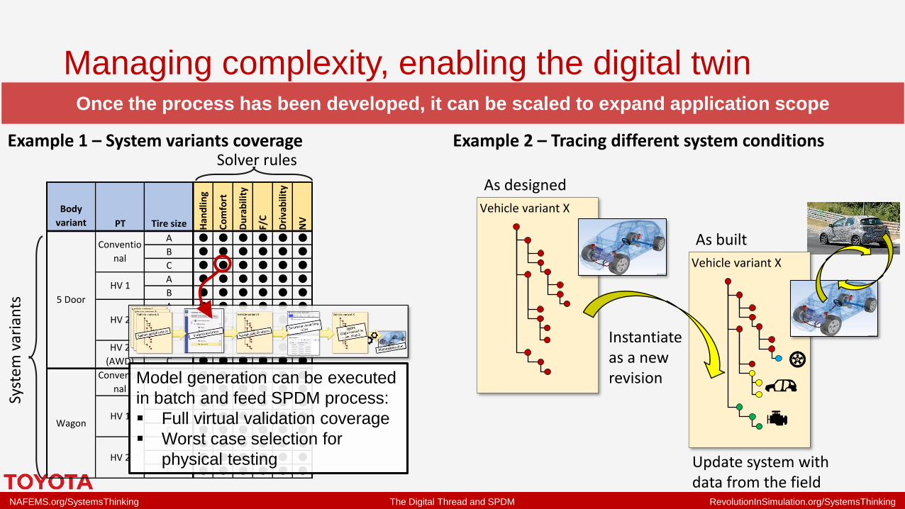
Once the process has been developed, it can be scaled to expand application scope
Managing complexity, enabling the digital twin

NAFEMS.org/SystemsThinking The Digital Thread and SPDM RevolutionInSimulation.org/SystemsThinking
Body
variant PT Tire size Han
dlin
g
Co
mfo
rt
Du
rab
ility
F/C
Dri
vab
ility
NV
A ● ● ● ● ● ●
B ● ● ● ● ● ●
C ● ● ● ● ● ●
A ● ● ● ● ● ●
B ● ● ● ● ● ●
A ● ● ● ● ● ●
B ● ● ● ● ● ●
C ● ● ● ● ● ●
B ● ● ● ● ● ●
C ● ● ● ● ● ●
A ● ● ● ● ● ●
B ● ● ● ● ● ●
A ● ● ● ● ● ●
B ● ● ● ● ● ●
C ● ● ● ● ● ●
A ● ● ● ● ● ●
B ● ● ● ● ● ●
C ● ● ● ● ● ●
HV 1
HV 2
Conventio
nal
HV 1
HV 2
HV 2
(AWD)
Conventio
nal
5 Door
Wagon
Example 1 – System variants coverage
Syst
em v
aria
nts
Solver rules
Once the process has been developed, it can be scaled to expand application scope
Model generation can be executed
in batch and feed SPDM process:
▪ Full virtual validation coverage
▪ Worst case selection for
physical testing
Example 2 – Tracing different system conditions
Vehicle variant X
As designed
Managing complexity, enabling the digital twin
NAFEMS.org/SystemsThinking The Digital Thread and SPDM RevolutionInSimulation.org/SystemsThinking
Body
variant PT Tire size Han
dlin
g
Co
mfo
rt
Du
rab
ility
F/C
Dri
vab
ility
NV
A ● ● ● ● ● ●
B ● ● ● ● ● ●
C ● ● ● ● ● ●
A ● ● ● ● ● ●
B ● ● ● ● ● ●
A ● ● ● ● ● ●
B ● ● ● ● ● ●
C ● ● ● ● ● ●
B ● ● ● ● ● ●
C ● ● ● ● ● ●
A ● ● ● ● ● ●
B ● ● ● ● ● ●
A ● ● ● ● ● ●
B ● ● ● ● ● ●
C ● ● ● ● ● ●
A ● ● ● ● ● ●
B ● ● ● ● ● ●
C ● ● ● ● ● ●
HV 1
HV 2
Conventio
nal
HV 1
HV 2
HV 2
(AWD)
Conventio
nal
5 Door
Wagon
Example 1 – System variants coverage
Syst
em v
aria
nts
Solver rules
Once the process has been developed, it can be scaled to expand application scope
Model generation can be executed
in batch and feed SPDM process:
▪ Full virtual validation coverage
▪ Worst case selection for
physical testing
Example 2 – Tracing different system conditions
Vehicle variant X
As designed
Vehicle variant X
As built
Instantiate as a new revision
Update system with data from the field
Managing complexity, enabling the digital twin

NAFEMS.org/SystemsThinking The Digital Thread and SPDM RevolutionInSimulation.org/SystemsThinking
Towards our vision for pervasive simulation

NAFEMS.org/SystemsThinking The Digital Thread and SPDM RevolutionInSimulation.org/SystemsThinking
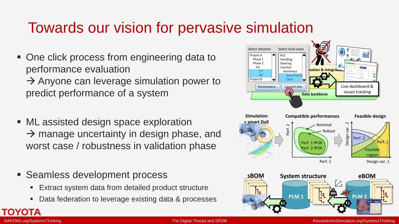
▪ One click process from engineering data to
performance evaluation
→ Anyone can leverage simulation power to
predict performance of a system
Process automation & integration
Data backbone
Select datasets Select load cases
Launch sim.Parameters…
Project APhase 1Phase 2
HV17”18”
Project B
KnCHandlingSteeringComfort
HarshnessSpeed bumpCleat
Live dashboard & issues tracking
Towards our vision for pervasive simulation

NAFEMS.org/SystemsThinking The Digital Thread and SPDM RevolutionInSimulation.org/SystemsThinking
▪ One click process from engineering data to
performance evaluation
→ Anyone can leverage simulation power to
predict performance of a system
▪ ML assisted design space exploration
→ manage uncertainty in design phase, and
worst case / robustness in validation phase
Process automation & integration
Data backbone
Select datasets Select load cases
Launch sim.Parameters…
Project APhase 1Phase 2
HV17”18”
Project B
KnCHandlingSteeringComfort
HarshnessSpeed bumpCleat
Live dashboard & issues tracking
Perf. 1
Per
f. 2 Nominal
Robust
Compatible performances
Design var. 1
Des
ign
var
. 2
Feasible design
Perf. 1Perf. 2
Feasible region
Perf. 1→OKPerf. 2→OK
Simulation+ smart DoE
Towards our vision for pervasive simulation
NAFEMS.org/SystemsThinking The Digital Thread and SPDM RevolutionInSimulation.org/SystemsThinking
▪ One click process from engineering data to
performance evaluation
→ Anyone can leverage simulation power to
predict performance of a system
▪ ML assisted design space exploration
→ manage uncertainty in design phase, and
worst case / robustness in validation phase
▪ Seamless development process
▪ Extract system data from detailed product structure
▪ Data federation to leverage existing data & processes
Process automation & integration
Data backbone
Select datasets Select load cases
Launch sim.Parameters…
Project APhase 1Phase 2
HV17”18”
Project B
KnCHandlingSteeringComfort
HarshnessSpeed bumpCleat
Live dashboard & issues tracking
Perf. 1
Per
f. 2 Nominal
Robust
Compatible performances
Design var. 1
Des
ign
var
. 2
Feasible design
Perf. 1Perf. 2
Feasible region
Perf. 1→OKPerf. 2→OK
Simulation+ smart DoE
PLM 2
Vehicle variant CVehicle variant B
Vehicle variant A
PLM 1
Vehicle variant CVehicle variant B
Vehicle variant A
eBOMSystem structureVehicle variant C
Vehicle variant BVehicle variant A
sBOM
Towards our vision for pervasive simulation

NAFEMS.org/SystemsThinking The Digital Thread and SPDM RevolutionInSimulation.org/SystemsThinking
Summary of our experience with the PoC project
The implementation of a system centric engineering data model was demonstrated,
including the feasibility of:
▪ A flexible single source of truth for system definition and related engineering data
▪ Easily accessing and re-using data for current and future processes
▪ Process automation and x-functional collaboration workflows
Enterprise deployment of SPDM is a steep path, but we moved firm steps in the right direction

NAFEMS.org/SystemsThinking The Digital Thread and SPDM RevolutionInSimulation.org/SystemsThinking
Conclusions – Today’s takeaway points• From Jay’s presentation
– When you design simulation models and their interaction mechanics, be aware that the single
source of truth changes over time – it is logically single, but physically distributed. Plan ahead for
the simulation workflow and model interaction to evolve, and keep up with the System Model.
– Future SPDMs have to support distributed, collaborative simulations. Current PLM-based
architectures cannot keep up with the complexity required for multidisciplinary, multi-physics SPDM.

NAFEMS.org/SystemsThinking The Digital Thread and SPDM RevolutionInSimulation.org/SystemsThinking
• From Jay’s presentation
– When you design simulation models and their interaction mechanics, be aware that the single
source of truth changes over time – it is logically single, but physically distributed. Plan ahead for
the simulation workflow and model interaction to evolve, and keep up with the System Model.
– Future SPDMs have to support distributed, collaborative simulations. Current PLM-based
architectures cannot keep up with the complexity required for multidisciplinary, multi-physics SPDM.
• From Ernesto’s presentation
– Automotive SPDM needs a flexible and system centric data model to be in place. Such data model
is not well developed for today’s system performance simulation domain, so it may need custom
development.
– SPDM has better value potential when it is 2-way connected to engineering data and surrounding
processes by the digital thread
Conclusions – Today’s takeaway points

NAFEMS.org/SystemsThinking The Digital Thread and SPDM RevolutionInSimulation.org/SystemsThinking
A call for action to accelerate SPDM
• Let’s not forget: SPDM ≠ one domain, one toolchain
(and new technology emerges any time)
• Demand your SW vendors to enable tool independent process integration
– Open data model to manage and exchange data across tools / disciplines
– Open APIs and standards, on top of black box connectors, for process integration
– Balance customisation with technical debt (easiness, sustainability)
• Team up at pre-competitive level to accelerate the technical development
– Clarify and consolidate requirements, share technology assessment
– Work with vendors to jointly develop demonstrators
Please get in touch if you are interested in collaborating on further development of
system centric SPDM

NAFEMS.org/SystemsThinking The Digital Thread and SPDM RevolutionInSimulation.org/SystemsThinking
Thank you for your attention
Please do not hesitate to get in touch with us:
▪ Jayendra Ganguli, [email protected]
▪ Ernesto Mottola, [email protected]
▪ Andrew Wood, [email protected]
▪ Malcolm Panthaki, [email protected]