Embed Size (px)
Citation preview

THE DEVELOPMENT OF RELAP5 FOR REACTOR SYSTEM ANALYSIS AND SIMULATION USE OF VISUALIZED MODULARIZATION SOFTWARE (RELAP-MV)
Eltayeb Yousif Harbin Engineering University Harbin, Heilongjiang, China
Zhijian Zhang Harbin Engineering University Harbin, Heilongjiang, China
Zhaofei Tian Harbin Engineering University Harbin, Heilongjiang, China
haoran Ju Harbin Engineering University Harbin, Heilongjiang, China
ABSTRACT
The RELAP5 code, designed to predict the behavior of reactor systems during accident conditions , is used widespread over the world. This work aims to show and describe the RELAP-MV graphical software developed using computer language (XML) and Visualized Modularization software technology to recognized best estimated transient simulation program of Light water reactor, in combination with new options for improved modeling methods, advanced programming, computational simulation techniques and integrated graphics displays. RELAP5 code is complex and inconvenient for utilizing method of data cards and close logic relationship of data in input file. The main purpose of developing RELAP5-MV is to simplify progress and increase simulation efficiency.
Traditional modeling method and modular modeling method are supported with RELAP5-MV to achieve aims of device and system simulation. For traditional modeling method, all kinds of components are developed such as single volume, single junction, pipe , branch , time dependent volume , etc. For modular modeling method , the module library is established in the software. The library packages include the main system equipments of primary and secondary loops such as reactor core, U tube steam generator, once through steam generator , pump , pressurizer, steam turbine, condenser, heat exchanger , deaerator ,etc. in a pressurized water reactor, which can be analyzed and modeled in details. From the library the capabilities are easy to select icons interface from the library packages. The analysis results show that the software can effectively simulate nuclear power system by RELAP5.
Plot and data binding function is supported for post-processing of calculation result. Personal computer interface of
RELAP5-MV makes it more convenient, fast and visualized in simulation system establishing process. Performance Relap5 related analysis activities, such as creating and modifying input file, viewing component division figures and generating output files can be realized by RELAP5-MV. The interactive simulation interface feature allows the users to simulate specific reactor transients and accidents– such as LOCA, LOFA, scram, etc. Accuracy and reliability of RELAP5-MV have already been confirmed by simulating main coolant system of Pressurize Water Reactor (PWR) and modeling efficiency increases significantly by using RELAP5-MV.
Visualization modeling, analysis and computational simulation for thermal hydraulic analysis of nuclear reactor can not only lower the RELAP5 threshold but also improve the efficiency of nuclear science research greatly, and also promoting the development of related research in RELAP5 safety analysis.
RELAP5-MV can give an approach to build, verify and assess simulation design of reactor power system. Keywords: Nuclear Safety, Modular Modeling methods, Relap5
INTRODUCTION
Relap5 played an important role in evaluating nuclear reactor systems for a wide range of planned and accidental conditions, and is the best-estimate program for light water reactor transient hydraulic and thermal analysis code, which is developed by Idaho National Engineering and Environmental Laboratory [1]. Most of these codes required high performance computers to simulate complicated reactor phenomena. However, rapid advances in computer
Proceedings of the 2016 24th International Conference on Nuclear Engineering ICONE24
June 26-30, 2016, Charlotte, North Carolina
ICONE24-60966
1 Copyright © 2016 by ASME

technology now enable these codes to run on personal computers or workstation in real or nearly real time [1]. Since 1985, when the first RELAP5/MOD2 was introduced, many changes have been made to make the code more realistic and user friendly, since it is difficult to simulate complex phenomena with the old version of code. Now the code is more complex to use with large range of analytical capability [2]. A RELAP5 problem input deck consists of at least one title card, optional comment cards, data cards, and a terminator card. A list of these input cards is printed at the beginning of each RELAP5 problem. For parameter studies and for temporary changes, a new title card with the inserted, modified, and deleted data cards and identifying comment cards should be placed just ahead of the terminating card [3 ].
Nuclear power plants may have potential severe hazard for public health and the environment during accidents. Power plant safety needs to be assessed and demonstrated using safety analysis. RELAP5 is one dimensional code, a highly generic that is used for simulating the behavior of a nuclear power plant during a transient. It is systematic a suitable and efficient code for nuclear power plant safety analysis [4].
In the reactor security analysis field, RELAP5 is utilized in many simulating calculation researches. It is shown by thousands of practical applications that RELAP5, with excellent reliability, plays an important role in thermo-hydraulics analysis of nuclear power system. But there are many disadvantages employing RELAP5: First of all, too many components make it hard and complex for beginners to understand and make use of RELAP5 due to over 10 categories of input cards with dozens of components. Then editing input cards by notepad, too many data with complex logic relationship makes up of input file, which makes it quite hard to modify and seek specific parameters. Lack of visualization, searching input file for information of equipment becomes a complicated task. Finally, because of the complex process of modeling and debugging, long time costs and productivity decreases. Oriented to solve these disadvantages, the graphical software RELAP-MV is developed using Extensive Makeup Language (XML) based on inner kernel model and solver of RELAP5 code. Utilized in actual numerical design of NPP, it is proven to raise modeling efficiency with RELAP5-MV.
DEVELOPED SIMULATION MODULES SOFTWARE FUNCTION DESIGN VISUAL INTERFACE DESIGN
RELAP5-MV provides two types of modeling methods: component modeling method and modular modeling method.
Component modeling method is a method of modeling to achieve system simulation task with experience of analyzing
configuration and operating characteristics of modeling objects. Table 1 shows classification table of RELAP5 basic input cards. Hydrodynamic components include single volume, single junction, pipe, branch, valve, separator, time-dependent volume, time-dependent junction, pump and accumulator and so on [5].
Table 1 Classification table of RELAP5 basic input cards[6] Type of component Function
Hydrodynamic component Simulate flow path
Thermal property data Show thermal property of heat structure
Control component Edit control method of nuclear system and control variable
Time-step control component
Control calculation time, time step and output frequency
General table component Input variable table
Heat structure Represent metal structures in a facility
Reactor kinetics component
Edit parameters in “point” reactor kinetics model
Problem control options
Set up parameters about problem and calculation
Trip component Set trip function Output component Control output process All of these components have their corresponding parts in RELAP5-MV, supporting component modeling method.
The simulation system of AP1000 NPP built using RELAP5-MV with component modeling method.
Input data file will be generated automatically for RELAP5 simulating calculation in background due to the regulation format with necessary modeling data filled in the interface according to the prompt. And RELAP5 executable program will be called to accomplish simulation task after is shown in Fig. 1.
During component modeling process, kinds of node division strategies will be tested to find the optimized one not only to cover every part and achieve main functions and performances of the equipment, but to show the static and dynamic properties accurately by calculation results as well. In another word, component modeling method is fit for skilled researchers.
2 Copyright © 2016 by ASME

Figure 1: Simulation system of AP1000 NPP built using RELAP5-MV with traditional method
In order to meet the requirement of rapid modeling, Modular modeling method is supported in RELAP5-MV, which is suggested to be used by freshman in RELAP5 simulation field. Modular modeling method is a modeling method using device modules in the module library to build simulation system directly. Prepared nuclear power device modules in advance due to standard structure, function and operating characteristics of devices, modules are collected in a module library embedded in RELAP5-MV.
Modular modeling method is adept in utilizing calculation resource, saving simulation cost and increasing modeling speed. Filling in parameters step by step in each device and then connecting with junctions, simulation system could be established more rapidly.
Thus, modular modeling method is able to act as one kind of technological means to realize rapid generation, validation and assessment of nuclear reactor system design.
Simulation system of primary and secondary loop of NPP with modular modeling method shown in Fig.2.
According to modular modeling technology, RELAP5-MV builds a module library including main devices working in system for energy transformation and transfer, including reactor core module (utilizing fuel pin and fuel plate), steam generator module (UTSG and OTSG), pump module, turbine module, condenser module, mixing heater module (i.e. used in deaerator simulation), shell-and-tube heat exchanger module (i.e. used in feed water heater simulation).
Node divisions of reactor core using fuel pin, UTSG, turbine and condenser are shown in Fig.3-6 as examples.
Sensitivity analysis of main flow pipes with heat transfer in each device has been done and recommended range of volume division number is given in Table 2 according to the result. The sensitivity analysis of Geometry, if it’s less than certain minimum value the result is not significant , and if sensitivity analysis of Geometry its greater than certain maximum value the calculation efficiency its going dawn sharply.
3 Copyright © 2016 by ASME

Figure 2: Primary and secondary loop simulation of NPP COMPRESSION OF RELAP5 GUIS: The main objective of Graphical User Interface (GUI) developed in the present work is to aid the RELAP user in preparation of input file [7]. The Implementation of a GUI for safety analysis of the ROSA/LSTF, it’s a bit similar of RELAP5-MV. GUI can be used to visualize the thermal hydraulics, heat transfer, fuel rod behaviour, controls, trip logic, etc. It also aids users in preparing the input model, running the calculations and plotting the results of their calculations. There is a variety of means to post process the data. The SNAP graphical user interface was designed to simplify the process of performing safety analysis. It is intended for creating and editing input for safety analysis codes and it has functionality for submitting, monitoring, and interacting with the codes. The SNAP interactive and post-processing capabilities are predominately realized within its animation displays. An animation display retrieves data from the server and represents it visually in some fashion. The data can be from an actively running calculation, a completed calculation, external data, etc [8]. The RELAP-GUI is developed in Microsoft Visual Studio using Visual C Sharp (C#) as programming language. The Nodalization diagram is drawn graphically and the program contains various component forms along with the starting data form, which are launched for properties assignment to generate Input File Cards serving as GUI for the user. The GUI is provided with Open / Save function to store and recall the Nodalization diagram along with Components’ properties. The GUI generated Input File is validated for several case studies and individual component cards are compared with the
originally required format. The generated Input File of RELAP is found consistent with the requirement of RELAP. The GUI provided a useful platform for simulating complex hydrodynamic problems efficiently with RELAP[9]. The greatest impact of RGUI on the RELAP5-3D program and user community will not be making the data easier to access or increasing the effectiveness of code users, although it does that. Rather it will be in three other areas: accessibility of RELAP5-3D to users, adaptation of RELAP5-3D to new trends in the computing industry, and incorporation of new and old capabilities into what will be perceived as RELAP5-3D. Among the most important reasons for creating RGUI is to make RELAP5-3D accessible to a broader group of people than currently use it. There are myriad ways that RGUI can benefit RELAP5 with respect to these groups. It helps them. In general, a GUI makes the program easier to access and start. It provides quick and easy access to documentation through multiple help features [10]. RELAP5-MVits more convents to accomplish system modular modeling methods than others GUIs, for provide many kind of equipment models, and rise up system building efficiency it used less time to get result.
4 Copyright © 2016 by ASME

Table 2 Recommended volume division number for devices
Devices Core(pin) Core(plate) UTSG OTSG
Volume division 10-50 10-50 10-20 50-80
Devices Pressurizer Condenser Heater Deaerator
Volume division 6 10 10 10
Table 3 Volume number VS Practice physical meaning of volumes
Volume number Physical meaning 102, 104 Inlet of pressure vessel
106 Downcomer 110 Bottom head 126 Upper head
433,933 Narrow flow path connected with upper head
112 Inlet of core 128,149 Average channel
114P Hot channel 116A Bypass channel 032 Outlet of core 120 Outlet of pressure vessel
Figure 3: Node divisions of reactor core
Figure 4: Main interface of RELAP5-MV
5 Copyright © 2016 by ASME
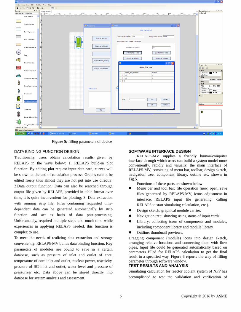
Figure 5: filling parameters of device DATA BINDING FUNCTION DESIGN Traditionally, users obtain calculation results given by RELAP5 in the ways below: 1. RELAP5 build-in plot function: By editing plot request input data card, curves will be shown at the end of calculation process. Graphs cannot be edited freely thus almost they are not put into use directly; 2.Data output function: Data can also be searched through output file given by RELAP5, provided in table format over time, it is quite inconvenient for plotting; 3. Data extraction with running strip file: Files containing requested time-dependent data can be generated automatically by strip function and act as basis of data post-processing. Unfortunately, required multiple steps and much time while experiences in applying RELAP5 needed, this function is complex to use. To meet the needs of realizing data extraction and storage conveniently, RELAP5-MV builds data binding function. Key parameters of modules are bound to save in a certain database, such as pressure of inlet and outlet of core, temperature of core inlet and outlet, nuclear power, reactivity, pressure of SG inlet and outlet, water level and pressure of pressurizer etc. Data above can be stored directly into database for system analysis and assessment.
SOFTWARE INTERFACE DESIGN
RELAP5-MV supplies a friendly human-computer interface through which users can build a system model more conveniently, rapidly and visually. the main interface of RELAP5-MV, consisting of menu bar, toolbar, design sketch, navigation tree, component library, outline etc, shown in Fig.5.
Functions of these parts are shown below: Menu bar and tool bar: file operation (new, open, save
files generated by RELAP5-MV, icons adjustment in interface, RELAP5 input file generating, calling RELAP5 to start simulating calculation, etc.).
Design sketch: graphical module carrier. Navigation tree: showing using status of input cards. Library: collecting icons of components and modules,
including component library and module library. Outline: thumbnail previews. Dragging component (module) icons into design sketch, arranging relative locations and connecting them with flow pipes, Input file could be generated automatically based on parameters filled for RELAP5 calculation to get the final result in a specified way. Figure 6 reports the way of filling parameter through software window. TEST RESULTS AND ANALYSIS Simulating calculation for reactor coolant system of NPP has accomplished to test the validation and verification of
6 Copyright © 2016 by ASME

visualized modularization method of RELAP5-MV. RCS with two primary circuits shown in Fig.6.
Figure 6: RCS of simulation
STEADY ANALYSIS OF THE PRIMARY SYSTEM
Data comparison between design data and calculation result is shown in Table 4. As reported in the table, relative errors of key parameters are all within 0.05% and 2.3%. So it is concluded that RELAP5-MV works in system steady analysis.
Table 4 Data comparison between design data and calculation result
Parameter Design value[11]
Simulation value
Relative error (%)
Pressure of core inlet (MPa) 15.51 15.83 2.1
Pressure of core (MPa)
15.51 15.87 2.3
Temperature of core inlet (K) 553.9 565.9 2.2
Temperature of core
outlet (K) 553.9 554.2 0.05
Pressure of pressurizer(MPa) 15.51 15.52 0.06
Total power(MW) 3400 3415 0.4
TRANSIENT ANALYSIS OF THE PRIMARY SYSTEM
Steam generator tube failure accident According to the Accuracy and reliability of RELAP5-MV have already been confirmed by simulating Steam generator tube failure accident and modeling efficiency increases significantly by using RELAP5-MV. The transient test scenario is modeled using the RELAP5-MV for the AP1000 NPP. The calculation was performed up to 3000.0 s of the transient time. Before running the investigated transient event, the RELAP5 model
was run in real plant equilibrium conditions up to 1500.0 s to establish steady state conditions at nominal reactor power
The initiating event of this analysis is the steam generator tube failure in SG#1. Since the primary system pressure is initially much greater than the steam generator pressure, reactor coolant flows from the primary into the secondary side of the affected steam generator [12]. Demonstrates considerable leakage at the beginning of the accident at 1500.0s because of the high pressure difference that exists between the primary and secondary side in the break position shown in Fig. 7. However the pressure decreases in the primary circuit in same time the pressure increases in the secondary side of the affected SG shown in Fig 8. The pressurizer level and RCS pressure decrease, for response to loss of reactor coolant.
Fast depressurization of the primary circuit and a rapid increase of the water level in the affected SG#1 characterize the initial phase of the transient shown in Fig.9. The pressure decrease, there is an actuation of the reactor scram due to the loss of offsite power (Offsite power is lost concurrent with the failure of the tube) and consequently, reactor power decreases shown in Fig 10. Coolant discharge leads to the further rapid decrease in pressure of the core outlet shown in Fig.11. After reactor scram, core power rapidly decreases to decay heat levels and also the core inlet to outlet temperature differential decreases as shown in Figs. 12, 13 and 14. The decrease of the reactor core temperature and leakage through steam generator tube failure results in a decrease of the reactor core pressure as shown in fig.15.
Finally, trend of this curves are reasonable, which proves that RELAP5-MV is able to simulate a nuclear power system accurately and reliably within the rapid convenient modular modeling method.
Figure7. Primary to secondary leak
7 Copyright © 2016 by ASME

Figure8:Pressure at SG#1 in primary loop
Figure 9: Water level of SG#1
Figure 10: Nuclear power
Figure 11: Pressure at the core outlet
…
Figure 12: Temperature at the core outlet.
Figure 13: Temperature at the core Inlet.
8 Copyright © 2016 by ASME

Figure 14: Temperature of core
Figure 15:.Pressure at the core
CONCLUSIONS
The RELAP5 model was developed for the transient analysis of the performance of a VVER-1000 nuclear power plant. The graphical software RELAP-MV is developed over the recognized best-estimate transient simulation program of light water reactor RELAP5 code.
Applying visualized personal- computer interface, component modeling method and modular modeling method is supported in RELAP5-MV. Using prepared nuclear power device modules designed by analyzing standard structure, function and operating characteristics in advance makes it more effective in utilizing calculation resource, saving simulation cost and increasing modeling speed.
Simulation process also becomes more convenient, visual and rapider. RELAP5-MV can increase simulation efficiency effectively according to simulation process of AP1000 NPP. The simulation result also pronounces accuracy and reliability of RELAP5-MV. RELAP5-MV could give an approach to build, verify and assess simulation design of reactor power system.
ACKNOWLEDGMENTS I would like to express my gratitude to my supervisor
Professor Zhang Zhijian, Professor TIAN Zhao-fei, Mr. Dong Xiao-meng and also I would like to thank our colleagues at Harbin Engineering University.
REFERENCES 1. K.D. Kima., Rizwan-uddin., 2007, “A web-based
nuclear simulator using RELAP5 and LabVIEW, Nuclear Engineering and Design,” Vol.237, pp 1185–1194.
2. M.H Talukder, et al., 2012, “Modelling of the Pactel sbl‐ 50 Transient Using RELAP5 Computer Code Department of Nuclear Engineering,” Vol. 262 , pp1653‐4662.
3. Rockville, Maryland. , 2002, “RELAP5/MOD3.3 CODE MANUAL VOLUME II:APPENDIX A INPUT REQUIREMENTS,” Information Systems Laboratories, Inc. Idaho Falls, Idaho, U. S. Nuclear Regulatory Commission Washington, DC 20555.
4. Xia, Z., et al., 2012, “The Analysis of PWR SBO Accident with RELAP5 Based on Linux, International Conference on Applied Physics and Industrial Engineering,” Vol. 24, pp 1329-1334.
5. C. D. Fletcher, R. Schultz., 2001, “RELAP5/MOD3.3 CODE MANUAL, VOLUME I:CODE STRUCTURE, SYSTEM MODEL AND SOLUTION METHODS,”. America: EG&G Idaho.Inc.
6. C. D. Fletcher, R. R. Schultz., 1995, “RELAP5/MOD3.3 CODE MANUAL,” VOLUME II: USER’S GUIDELINES. America: EG&G Idaho.Inc.
7. R.R. Schultz, “RELAP5 Code Manual Volume V: User’s Guidelines,” Idaho National Engineering and Environmental Laboratory Bechtel BWXT Idaho, LLC.
8. Andrej Prošek., 2011, “Implementation of a graphical user interface for safety analysis of the ROSA/LSTF hot-leg break experiment,” Jožef Stefan Institute, Jamova cesta 39, SI-1000 Ljubljana, Slovenia LEKTROTEHNIŠKI VESTNIK 78(3): 147-152.
9. M.M. ANWAR, A.A. KHAN etal.,2009, “DEVELOPMENT AND VALIDATION OF GUI BASED INPUT FILE GENERATION CODE FOR RELAP,” The Nucleus, DOS, Pakistan Atomic Energy Commission, Islamabad, Pakistan 46 (3) 2009 : 183-186.
10. George Mesina & Jim Galbraith.,2000, “New Developments and Value of the RELAP5-3D Graphical User Interface (RGUI 1.2),” Idaho Falls, ID 83415-
9 Copyright © 2016 by ASME

3880, USA, Jackson Hole, WY, USA, 12-14, 2000AD. 11. J.W. Winters, J. A. Clelland., 2004, “AP1000 Design
And Construction Integration,” ICAPP’04-4254. 12. Groudev PP., AE., et al., 2004, “RELAP5/ MOD3.2
investigation of primary-to-secondary reactor coolant
leakage in VVER-440,” J Nucl Eng Des., Vol. 31, pp961–74.
10 Copyright © 2016 by ASME