Embed Size (px)
Citation preview

THERMAL HYDRAULIC ANALYSIS FOR THE OREGON STATE
REACTOR USING RELAP5-3D
Wade R. MarcumBrian G. Woods
2007 TRTR ConferenceSeptember 19, 2007

Wade Marcum 2007 TRTR Conference September 19
Outline
• Project Introduction/Objective
• Benchmark Methodology
• Oregon State TRIGA® Reactor Overview
• RELAP5-3D Model
• HEU Benchmark Results
• Steady State (BOL)
• Pulse (EOL)
• Experimental Measurements
• Conclusion
THERMAL HYDRAULIC ANALYSIS FOR THE OREGON STATE REACTOR USING RELAP5-3D

THERMAL HYDRAULIC ANALYSIS FOR THE OREGON STATE REACTOR USING RELAP5-3D
Project Introduction/Objective
Oregon State University has completed its core conversion analysis as part of the Reduced Enrichment for Research and Test Reactors (RERTR) program. As part of the core conversion analysis, the Nuclear Regulatory Commission (NRC) has required that complete neutronic and thermal hydraulic analyses be conducted on the existing OSTR (HEU) and potential (LEU) core. The goals of the thermal hydraulic analyses were to:
• Calculate natural circulation flow rates, coolant temperature and fuel temperatures as a function of core power for both the HEU and LEU cores.
• For steady state and pulsed operation, calculate peak values of the fuel temperature, cladding temperature, surface heat flux as well as departure from nucleate boiling ratio (DNBR) and temperature profiles in the hot channel for both the HEU and LEU cores.
• Perform accident analyses for the accident scenarios identified in the OSTR Safety Analysis Report (SAR).
Wade Marcum 2007 TRTR Conference September 19
THERMAL HYDRAULIC ANALYSIS FOR THE OREGON STATE REACTOR USING RELAP5-3D
Benchmark Methodology
Wade Marcum 2007 TRTR Conference September 19
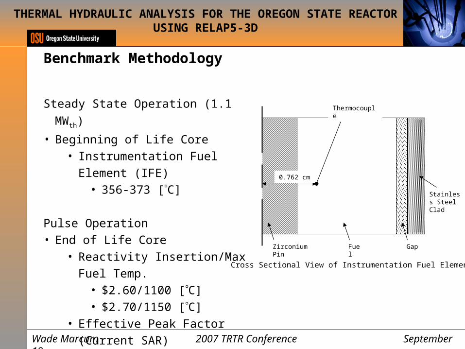
Steady State Operation (1.1 MWth)
• Beginning of Life Core• Instrumentation Fuel Element (IFE)
• 356-373 [C]
Pulse Operation• End of Life Core
• Reactivity Insertion/Max Fuel Temp.• $2.60/1100 [C]• $2.70/1150 [C]
• Effective Peak Factor (Current SAR)• 3.41
Cross Sectional View of Instrumentation Fuel Element
Zirconium Pin Fuel Gap
Stainless Steel Clad
0.762 cm
Thermocouple
THERMAL HYDRAULIC ANALYSIS FOR THE OREGON STATE REACTOR USING RELAP5-3D
Oregon State TRIGA® Reactor Overview
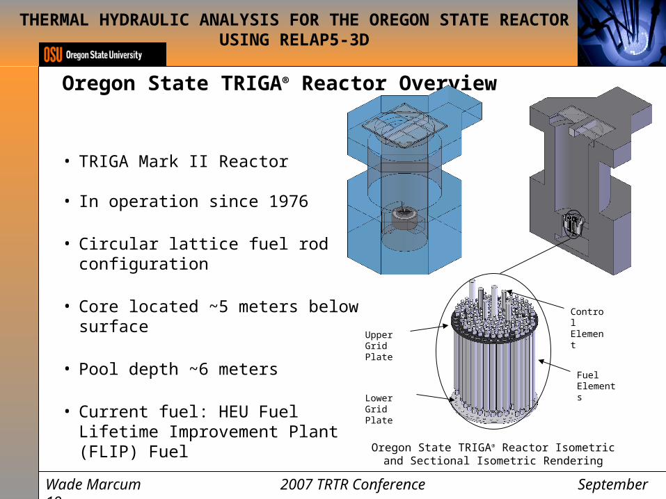
• TRIGA Mark II Reactor
• In operation since 1976
• Circular lattice fuel rod configuration
• Core located ~5 meters below surface
• Pool depth ~6 meters
• Current fuel: HEU Fuel Lifetime Improvement Plant (FLIP) Fuel
Lower Grid Plate
Upper Grid Plate
Fuel Elements
Control Element
Oregon State TRIGA® Reactor Isometric and Sectional Isometric Rendering
Wade Marcum 2007 TRTR Conference September 19
THERMAL HYDRAULIC ANALYSIS FOR THE OREGON STATE REACTOR USING RELAP5-3D
Oregon State TRIGA® Reactor Overview
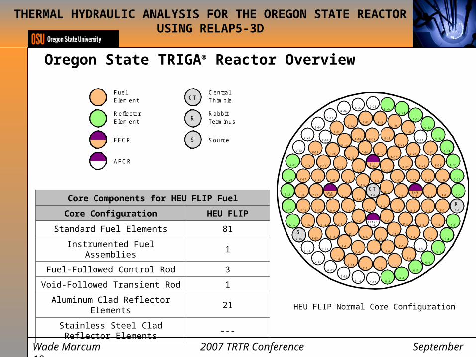
Core Components for HEU FLIP Fuel
Core Configuration HEU FLIP
Standard Fuel Elements 81
Instrumented Fuel Assemblies 1
Fuel-Followed Control Rod 3
Void-Followed Transient Rod 1
Aluminum Clad Reflector Elements 21
Stainless Steel Clad Reflector Elements ---
R
S
R
S
R
S
CT
B-1
B-2B-3
B-4
B-5B-6
C-1
C-2
C-3C-4
C-5
C-6
C-7
C-8
C-9C-10
C-11
C-12
SHIM
REG
TRANS
SAFED-1
D-2
D-3
D-4
D-5D-6D-7
D-8
D-9
D-10
D-11
D-12
D-13
D-14 D-15D-16
D-17
D-18
E-1
E-2
E-3
E-4
E-5
E-6E-7E-8
E-9
E-10
E-11
E-12
E-13
E-14
E-15
E-16
E-17
E-18 E-19 E-20
E-21
E-22
E-23
E-24
F-1
F-2
F-3
F-4
F-5
F-6
F-7F-8F-9
F-10
F-11
F-12
F-13
F-14
F-15
F-16
F-17
F-18
F-19
F-20
F-21
F-22F-23 F-24
F-25
F-26
F-27
F-28
F-29
F-30
G-1
G-2
G-3
G-4
G-5
G-6
G-7
G-8G-9G-10G-11
G-12
G-13
G-14
G-15
G-16
G-17
G-18
G-19
G-20
G-21
G-22
G-23
G-24
G-25
G-26G-27 G-28
G-29G-30
G-31
G-32
G-33
G-34
G-35
G-36
Fuel Element
Reflector Element
FFCR
AFCR
Central Thimble
RabbitTerminus
Source
A-1
CT
HEU FLIP Normal Core Configuration
Wade Marcum 2007 TRTR Conference September 19
R
S
R
S
R
S
CT
B-1
B-2B-3
B-4
B-5B-6
C-1
C-2
C-3C-4
C-5
C-6
C-7
C-8
C-9C-10
C-11
C-12
SHIM
REG
TRANS
SAFED-1
D-2
D-3
D-4
D-5D-6D-7
D-8
D-9
D-10
D-11
D-12
D-13
D-14 D-15D-16
D-17
D-18
E-1
E-2
E-3
E-4
E-5
E-6E-7E-8
E-9
E-10
E-11
E-12
E-13
E-14
E-15
E-16
E-17
E-18 E-19 E-20
E-21
E-22
E-23
E-24
F-1
F-2
F-3
F-4
F-5
F-6
F-7F-8F-9
F-10
F-11
F-12
F-13
F-14
F-15
F-16
F-17
F-18
F-19
F-20
F-21
F-22F-23 F-24
F-25
F-26
F-27
F-28
F-29
F-30
G-1
G-2
G-3
G-4
G-5
G-6
G-7
G-8G-9G-10G-11
G-12
G-13
G-14
G-15
G-16
G-17
G-18
G-19
G-20
G-21
G-22
G-23
G-24
G-25
G-26G-27 G-28
G-29G-30
G-31
G-32
G-33
G-34
G-35
G-36
Fuel Element
Reflector Element
FFCR
AFCR
Central Thimble
RabbitTerminus
Source
A-1
CT

THERMAL HYDRAULIC ANALYSIS FOR THE OREGON STATE REACTOR USING RELAP5-3D
Oregon State TRIGA® Reactor Overview
Comparison of HEU FLIP Fuel Designs
Fuel Type HEU FLIP
Uranium content [mass %] 8.5
U-235 enrichment [mass % U] 70
Erbium content [mass %] 1.6
Fuel alloy inner diameter [mm] 6.35
Fuel alloy outer diameter [mm] 36.449
Fuel alloy length [mm] 381
Cladding material Type 304 SS
Cladding thickness [mm] 0.508
Cladding outer diameter [mm] 37.465
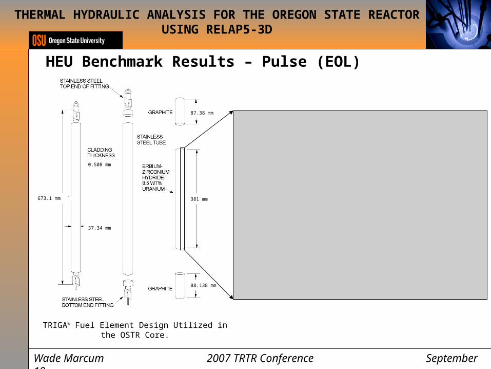
TRIGA® Fuel Element Design Utilized in the OSTR Core.
87.38 mm
381 mm
88.138 mm
37.34 mm
0.508 mm
673.1 mm
Wade Marcum 2007 TRTR Conference September 19
THERMAL HYDRAULIC ANALYSIS FOR THE OREGON STATE REACTOR USING RELAP5-3D
Oregon State TRIGA® Reactor Overview
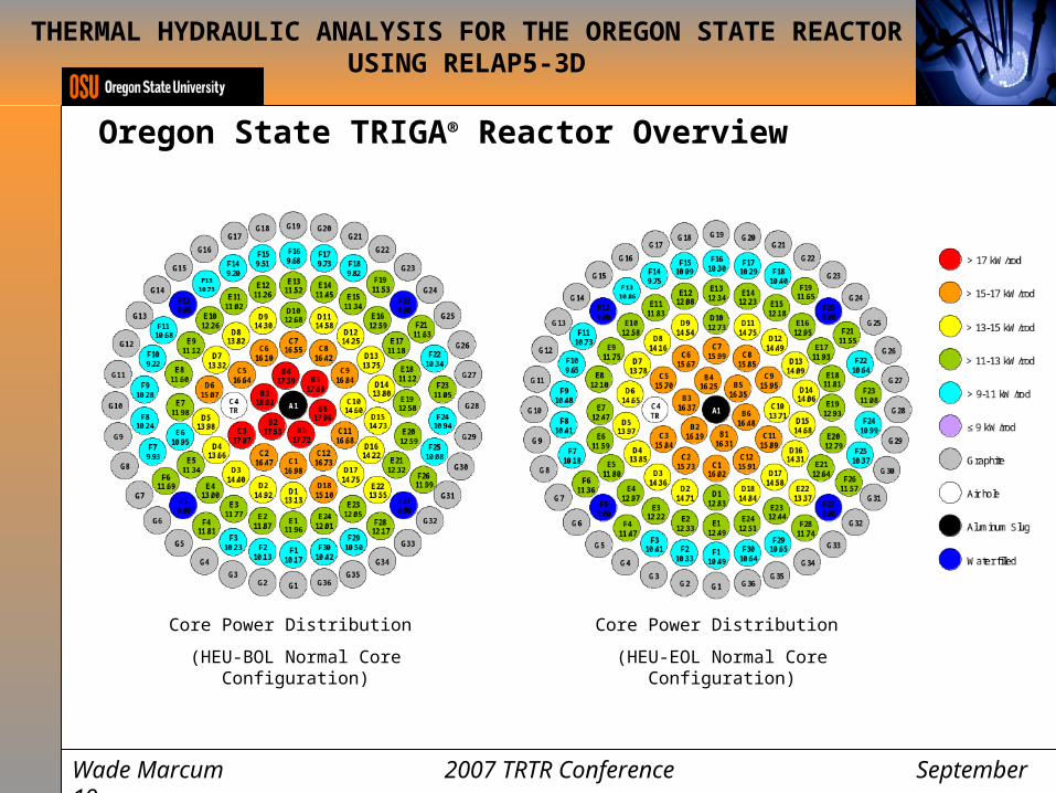
Core Power Distribution
(HEU-BOL Normal Core Configuration)
Wade Marcum 2007 TRTR Conference September 19
Core Power Distribution
(HEU-EOL Normal Core Configuration)
THERMAL HYDRAULIC ANALYSIS FOR THE OREGON STATE REACTOR USING RELAP5-3D
Oregon State TRIGA® Reactor Overview
Wade Marcum 2007 TRTR Conference September 19
0
0.5
1
1.5
2
-20
-10
0
10
200
20
40
60
80
100
120
140
Radial Dist. From Fuel Centerline [cm]Axial Dist. From Fuel Centerline [cm]
Pow
er
[W]
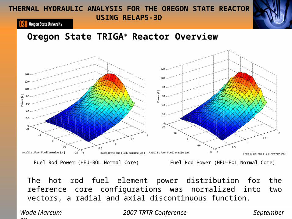
Fuel Rod Power (HEU-BOL Normal Core)
0
0.5
1
1.5
2
-20
-10
0
10
200
20
40
60
80
100
120
Radial Dist. From Fuel Centerline [cm]Axial Dist. From Fuel Centerline [cm]
Pow
er
[W]
Fuel Rod Power (HEU-EOL Normal Core)
The hot rod fuel element power distribution for the reference core configurations was normalized into two vectors, a radial and axial discontinuous function.

THERMAL HYDRAULIC ANALYSIS FOR THE OREGON STATE REACTOR USING RELAP5-3D
Oregon State TRIGA® Reactor Overview
Wade Marcum 2007 TRTR Conference September 19
These two vectors were then input into the RELAP5-3D model
0
0.5
1
1.5
2
2.5
3
3.5
0 0.5 1 1.5 2
Radial Distance From Fuel Centerline [cm]
Pow
er F
acto
r
HEU-BOL Normal
HEU-EOL Normal
Radial Power Factor Distribution
0
0.2
0.4
0.6
0.8
1
1.2
1.4
-20 -15 -10 -5 0 5 10 15 20
Axial Distance From Fuel Centerline [cm]
Pow
er F
acto
r
HEU-BOL NormalHEU-EOL Normal
Axial Power Factor Distribution

THERMAL HYDRAULIC ANALYSIS FOR THE OREGON STATE REACTOR USING RELAP5-3D
RELAP5-3D Model
Wade Marcum 2007 TRTR Conference September 19
Coolant Source
Cold Leg
Horizontal Connector
Hot Channel
Coolant Sink
Schematic of RELAP5-3D model
Geometric/Hydraulic Hot Channel Inputs Implemented in RELAP5-3D
Geometric/Hydraulic Description Value
Unheated core length at inlet [m] 0.1655
Unheated core length at outlet [m] 0.1647
Inlet pressure loss coefficient 1.29
Exit pressure loss coefficient 0.574
Absolute pressure at the top of the core [Pa] 1.49E5
Inlet coolant temperature [C] 49.0
Flow area [m2] 3.304E-04
Wetted perimeter [m] 0.1177
Hydraulic diameter [m] 2.051E-02
Fuel element heated length [m] 0.381
Fuel element surface area [m2] 3.810E-1
Fuel element surface roughness [m] 2.134E-06

THERMAL HYDRAULIC ANALYSIS FOR THE OREGON STATE REACTOR USING RELAP5-3D
HEU Benchmark Results – Steady State (BOL)
Wade Marcum 2007 TRTR Conference September 19
400
450
500
550
600
650
700
750
800
0 0.005 0.01 0.015 0.02
Radial Distance From Fuel Element Center [m]
.05 mil Gap
.10 mil Gap
.15 mil Gap
.20 mil GapIFE Measurement
Fuel Element Radial Temperature Distribution at 1.1 MWthT
empe
ratu
re [
K]
A radial temperature profile at 1.1 MWth
integral core steady state power was mapped while varying the fuel to clad gap from 0.05 to 0.20 mils, the corresponding temperature was compared to that found in the IFE during the original 1976 core configuration. As a result of this figure a clad gap of 0.1 mils was used in all core configurations.
THERMAL HYDRAULIC ANALYSIS FOR THE OREGON STATE REACTOR USING RELAP5-3D
HEU Benchmark Results – Steady State (BOL)
Wade Marcum 2007 TRTR Conference September 19
0
100
200
300
400
500
600
700
800
900
1000
0 10 20 30 40
Hot Channel Fuel Element Power [kW]
0.02
0.04
0.06
0.08
0.10
0.12
0.14
0.16
Fuel CenterlineOuter CladdingBulk CoolantCoolant Mass Flow
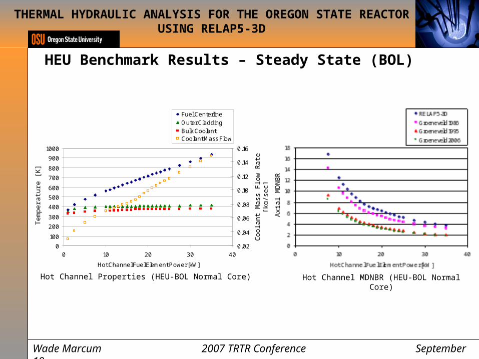
Hot Channel Properties (HEU-BOL Normal Core)
Tem
pera
ture
[K
]
Coo
lant
Mas
s Fl
ow R
ate
[kg/
sec]
Hot Channel MDNBR (HEU-BOL Normal Core)A
xial
MD
NB
R

THERMAL HYDRAULIC ANALYSIS FOR THE OREGON STATE REACTOR USING RELAP5-3D
HEU Benchmark Results – Steady State (BOL)
Wade Marcum 2007 TRTR Conference September 19
Hot Channel Axial DNBR at 18.02 kW (HEU-BOL Normal Core)D
NB
R
The figure represents the axial DNBR when the hot channel is at 18.02. The methods for calculating DNBR shown use the results produced from RELAP5-3D to apply the appropriate correction factors used in the Groeneveld 1986 [1], 1995 [2], and 2006 [3] AECL-UO look-up tables. The MDNBR value produced from the bounding DNBR method, Groeneveld 2006, is 3.420.

THERMAL HYDRAULIC ANALYSIS FOR THE OREGON STATE REACTOR USING RELAP5-3D
HEU Benchmark Results – Pulse (EOL)
Wade Marcum 2007 TRTR Conference September 19
The pulsing performance of the reactor was analysed using a point reactor kinetics model. With this methodology and the fissile fuel characteristics produced from the MCNP5 analysis a pulse power trace was developed for given reactivity insertions [4].
1.E-03
1.E-02
1.E-01
1.E+00
1.E+01
1.E+02
1.E+03
1.E+04
1.E+05
0.000 0.010 0.020 0.030 0.040 0.050
Time [sec]
1.E-03
1.E-02
1.E-01
1.E+00
1.E+01
1.E+02
1.E+03
1.E+04
1.E+05
$2.60 Power $2.70 Power $2.90 Power
$2.60 Energy $2.70 Energy $2.90 Energy
Pow
er [
MW
]
Ene
rgy
[MJ]
HEU-EOL Normal Core Pulse Trace
THERMAL HYDRAULIC ANALYSIS FOR THE OREGON STATE REACTOR USING RELAP5-3D
HEU Benchmark Results – Pulse (EOL)
Wade Marcum 2007 TRTR Conference September 19
,
0.18 0.009HEU LEU FUEL
K T
3
,2.04 4.17 10P HEU LEU FUEL
C T T
[W-sec/cm3-C]
[W/cm-C]
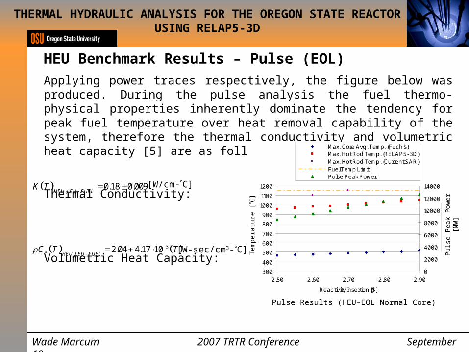
Applying power traces respectively, the figure below was produced. During the pulse analysis the fuel thermo-physical properties inherently dominate the tendency for peak fuel temperature over heat removal capability of the system, therefore the thermal conductivity and volumetric heat capacity [5] are as follows:
Thermal Conductivity:
Volumetric Heat Capacity:
300
400
500
600
700
800
900
1000
1100
1200
2.50 2.60 2.70 2.80 2.90
Reactivity Insertion [$]
0
2000
4000
6000
8000
10000
12000
14000
Max. Core Avg. Temp. (Fuch's)Max. Hot Rod Temp. (RELAP5-3D)Max. Hot Rod Temp. (Current SAR)Fuel Temp LimitPulse Peak Power
Pulse Results (HEU-EOL Normal Core)
Puls
e Pe
ak P
ower
[M
W]
Tem
pera
ture
[C
]
THERMAL HYDRAULIC ANALYSIS FOR THE OREGON STATE REACTOR USING RELAP5-3D
HEU Benchmark Results – Pulse (EOL)
Wade Marcum 2007 TRTR Conference September 19
TRIGA® Fuel Element Design Utilized in the OSTR Core.
87.38 mm
381 mm
88.138 mm
37.34 mm
0.508 mm
673.1 mm

THERMAL HYDRAULIC ANALYSIS FOR THE OREGON STATE REACTOR USING RELAP5-3D
Experimental Measurements
Wade Marcum 2007 TRTR Conference September 19
Equipment Brand Model Number Serial Number
Thermocouple Gordon K Type G16308
GPIB/USB Interface Cable HP Agilent 82379A X1307A2
DAQ Bucket HP Agilent 34970A 11298
Computer Dell E1705 F5PF1B1

Experimental Measurements
• This analysis was conducted to provide general coolant temperature profile trends within the OSTR core in order to compare values to the OSTR RELAP5 model.
• Axial temperature distributions at six different radial locations within the core were produced during this analysis.
• The OSTR core fuel configuration is skewed symmetrically to one side; it is assumed that this produces hotter coolant temperature values along this radial direction than generally found elsewhere in the core.
THERMAL HYDRAULIC ANALYSIS FOR THE OREGON STATE REACTOR USING RELAP5-3D
Experimental Measurements
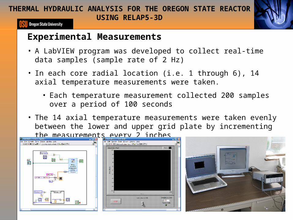
• A LabVIEW program was developed to collect real-time data samples (sample rate of 2 Hz)
• In each core radial location (i.e. 1 through 6), 14 axial temperature measurements were taken.
• Each temperature measurement collected 200 samples over a period of 100 seconds
• The 14 axial temperature measurements were taken evenly between the lower and upper grid plate by incrementing the measurements every 2 inches
THERMAL HYDRAULIC ANALYSIS FOR THE OREGON STATE REACTOR USING RELAP5-3D
Experimental Measurements
0
5
10
15
20
25
30
35
40
45
50
0 10 20 30 40 50 60 70
Axial Distance From Lower Grid Plate [cm]
Tem
pera
ture
[°C
]
Experimental
RELAP5-3D
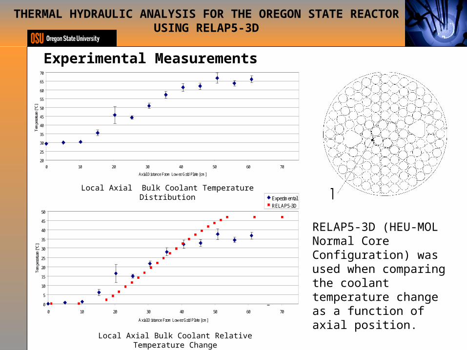
Local Axial Bulk Coolant Temperature Distribution
THERMAL HYDRAULIC ANALYSIS FOR THE OREGON STATE REACTOR USING RELAP5-3D
20
25
30
35
40
45
50
55
60
65
70
0 10 20 30 40 50 60 70
Axial Distance From Lower Grid Plate [cm]
Tem
pera
ture
[°C
]
Local Axial Bulk Coolant Relative Temperature Change
RELAP5-3D (HEU-MOL Normal Core Configuration) was used when comparing the coolant temperature change as a function of axial position.
Experimental Measurements
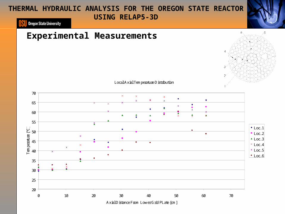
Local Axial Temperature Distribution
20
25
30
35
40
45
50
55
60
65
70
0 10 20 30 40 50 60 70
Axial Distance From Lower Grid PLate [cm]
Tem
pera
ture
[°C
] Loc. 1
Loc. 2
Loc. 3
Loc. 4
Loc. 5
Loc. 6
THERMAL HYDRAULIC ANALYSIS FOR THE OREGON STATE REACTOR USING RELAP5-3D

Conclusion
• The steady state fuel temperature at 1.1 MWth reflects that found in the IFE by
applying a fuel/clad contact gap thickness of 1.0 mils to within a relative error margin.
• The hot channel maximum fuel temperature during a pulse reflects that in the current SAR within ~100 [C].
• The experimental temperature measurements taken provide evidence that the RELAP5-3D model produces conservative results to that found in the physical OSTR.
• Through the benchmark methodology presented, the thermal hydraulic analysis conducted during this core conversion projects produces conservative and relatively accurate results.
THERMAL HYDRAULIC ANALYSIS FOR THE OREGON STATE REACTOR USING RELAP5-3D

References
THERMAL HYDRAULIC ANALYSIS FOR THE OREGON STATE REACTOR USING RELAP5-3D
[1] Groeneveld, D.C., et al., The 2006 CHF look-up table. Nuclear Engineering and Design, 2007: p. 1-24.
[2] Groeneveld, D.C., S.C.Cheng, and T. Doan, 1986 AECL-UO Critical Heat Flux Lookup Table. Heat Transfer Engineering, 1986. 7(1-2): p. 46-62.
[3] Groeneveld, D.C., et al., The 1995 look-up tables for critical heat flux in tubes. Nuclear Engineering and Design, 1996. 1(23): p. 1-23.
[4] Safety analysis report for the conversion of the Oregon State TRIGA Reactor from HEU to LEU fuel, in Documentation of analyses of conversion of the Oregon State University TRIGA reactor from HEU to LEU fuel. 2007, Oregon State University: Corvallis.
[5] Simnad, M., F. Foushee, and G. West, Fuel elements for pulsed TRIGA Research Reactors. 1975, General Atomics: Sandiego, CA.

Questions
THERMAL HYDRAULIC ANALYSIS FOR THE OREGON STATE REACTOR USING RELAP5-3D


![Revision and Exam Tips - New SMART website · =====trtrt]=-tr-trtrtrtrtrtr-tr F 1F]ilflfrritfltrft tr-trtr=tr tr=tr==tr tr-tlF-lflft 71 trtr=trtrtr=tr trtrtrtrtr=trtr trtrtrtrtr==tr](https://img.dokumen.tips/doc/110x75/5ed679a2e7ed90307a0783ea/revision-and-exam-tips-new-smart-trtrt-tr-trtrtrtrtrtr-tr-f-1filflfrritfltrft.jpg)