Embed Size (px)
Citation preview

THE DEVELOPMENT OF A NEW AIR JIG FOR DRY COAL BENEFICATION
Lars Weitkämper and Hermann Wotruba RWTH Aachen, Department of Mineral Processing, Aachen, Germany. E-mail: wcitkac111pcr(i1 a111r.rwth-a8che11.dc
ABSTRACT
Dry coal dressing was popular during the 1950's and 60's in many parts of the world. The devices mainly used were air jigs and air tables.
The increase in ash and moisture content of run-of-mine coals due to the wide advanced mechanisation of mining mechanisation during and after this period led to that pneumatic devices being unable to treat run-ofmine coals with the desired efficiency. Since the l 960's almost all new coal preparation plants have been based on wet processes that are highly efficient in terms of coal recovery and their ability to handle damp and sticky run-of-mine coals . (Frankland, 1995)
However, water is becoming increasingly costly and the disposal of fine products, containing most of the water, is an environmental concern. There would be significant cost savings and a lower total energy consumption if coal could be cleaned dry. Efficient dry coal treatment would be an interesting solution in desert, arid or cold areas.
In Germany one dry coal dressing plant is in operation. The process and the advantages and disadvantages are presented below.
Further on new developments in the field of dry density separation of coal are reviewed and analysed. Test results of new dry coal separation methods e.g. new developed air jig and magnetic separator are reported.
Keywords : air jig, coal benefication, density separation, automatic process control
INTRODUCTION
This article is supposed to give an overview of the research activities done at the Department of Mineral Processing, Technical University of RWTH Aachen, Gennany in dry coal dressing.
The actual technical standard of dry coal dressing has been analysed during test-work and sampling in the Saarwellingen plant (Saar Region in Gennany). This is the last operating dry coal dressing plant existing in Europe. The tasks on improvement of dry coal dressing and test-work for the optimisation will be reported. The aim of the research work is the development of an improved process including the main sorting device a new developed air j ig for dry coal dressing.
DRY COAL DRESSING TODA Y
Test-work and sampling at the dry coal dressing plant in Saarwellingen, Germany The "Grube Raisbach" in Saarwellingen (Saar Region) is the last operating dry coal dressing plant in
Europe. The operation staited in 1959 and the produced coal is high-ash coal, only suitable for electric power plants. (Padberg, 1989)
Proceedings: XX II International Mineral Process ing Congress Chief Editors: L. Lorenzen and D.J . Bradshaw ISBN: 0-958-46092-2
613
29 September - 3 October 2003 Cape Town, South Africa
Produced by: Docurnent Transformation Techno logies
•

.---~
/ '.'li.l"l 'l '.._I
• ·.l" •o'•' ; f. t
, ,-,1 1.r 11 s l ·c1
r•·:. 1. ·1.-..t.r
·.· 1 \.· 1• 11
~)•f ;,1 1. '·
l
J bin bm
Figure 1. Process flowsheet of the Saarwellingen plant.
-
·1 ; 11 1111 1,_•1
·111 !1
Ulll
The main reason for a dry operating plant was the Jack of an environmental permit for a wet process. Figure 1 illustrates the flowsheet of the dry coal preparation plant in Saarwellingen, Germany.
The run of mine coal is transported by trucks to the preparation plant. lt is pre-screened at 30 mm. The oversize is crushed by a jaw crusher and then mixed directly to the underflow of the pre-screening. Afterwards the material is screened on a three deck circular oscillating screen into the fractions +30 mm, 6-30 mm and -6 mm. The oversize is crushed by a roll crusher, the mid size screening product is fed to the separation plant and the underflow is blended unsorted to the product.
The Berry table is most efficient when fed with a narrow size fraction. Therefore the material 6-30 mm is classified on vibrating screens with long hole screen decks into four fractions, (6-10 mm, 10-16, 16-20, 20-30) as a preparation for the separation.
The classified material is fed to five air tables (two for the 6-10 mm fraction). The coal product is blended with the - 6 mm fraction and crushed in a hammer mill.
Investigations during the development of the applied process showed that it is uneconomically to process the -6 mm fraction applying air tables, because of their low capacity in this size fraction. (Groß, 1982)
Performance and evaluation of the Saarwellingen plant
Figure 2: The Berry air table, Saarwellingen plant.
614

100 --90
80 ~ 70
~.-<'.'. ""
1/
/ .5 ;;: 60 0
't 50 "' "O c 40 ::> c
30 "' l" 0 20 "'
,/ / '
~ )V _,_
~
10 - c------~
0
0 size in [mm]
10 100
Figure 3. Particle size ofthe run ofmine coal.
Figure 2 shows the Berry air table. Figure 3 shows the particle size of the ROM coal. Coal coarser than 30 mm is not suitable for the Berry tables. Because of this reason about 50 % of the ROM coal has to be crushed with the roll crusher. This results not only in a higher energy consumption, but produces more fine product -6 mm, which cannot be treated efficiently on the air tables. (Weiss, 1985)
60
,.....--50 - .......---
~ 40 -0 - ............. 1
.s c 30 --Cl> c 0 20 -0 -
.r:: (/)
"' 10
0
0-1 1-2 2-6 6-10 10-16 16-20 20-30 total
size in [mm]
Figure 4. Ash contents of the different size ranges.
Figure 4 shows the ash content of the ROM coal after crushing. The fraction -6 mm has an ash content as high than the fractions that get sotted on the air tables.
Pe1for111ance of the Berry air tables
100 90 80
~ 70
.s 60
c 50 ofeed
• coal Ql
40 c 0 30 0 .r: 20 "' oshale
"' 10 0
6-10 10-16 16-20 20-30 pure
siiein [mm]
Figure 5. Ash content offeed, product and shale of the Berry air tables, Saarwellingen plant.
6 15

In Figure 5 the ash content of the feed and products of the air tables as weil as pure specimens of coal and shale are illustrated. The black bar on the right side shows the ash content of a pure piece of coal and the grey bar illustrates the ash content of a pure piece of shale. This represents the best possible sorting result.
The sorting results are similar in each fraction. The run of mine coal has an average ash content of about 40 %. The light product ( coal) has an ash content below 20 % except for the 10-6 mm fraction, due to the fact that it is more difficult to sort fine fractions on the air table e.g. 6-10 mm with 22 % ash content.
The heavy product (shale) has an ash content in all size fractions of about 80 %, which means nearly no losses of coal. This is an outstanding result for a dry process.
Summary of the Saarwellingen plant process Advantages:
• excellent separation efficiency • simple process, no breakdowns • no water circuit needed
Disadvantages: • the - 6 mm fraction is blended unsorted to the product (too fine for the air tables) and downgrades the
product • the coal + 30 mm has to be crushed because it is too coarse for the air tables, although it is not intergrown • labour intensive control and adjustment of the Berry-tables • throughput of the Berry-tables is limited to about 6 tons per meter width and hour • high energy costs are resulting from the high air consumption of the air tables • (Weitkämper, 2001)
T ASKS ON THE IMPROVEMENT OF DRY COAL DRESSING
A modern dry coal separation technology has to be improved in the following fields: • Separation of coarse, free material + 30 mm • High throughput of medium-sized material • Efficient separation of fine material -6 mm
lt was obvious, that all these demands cannot be performed with one single machine. Therefore a process had to be developed which uses different devices for different size fractions.
Coarse size: Use of improved air jigs with the possibility to process non-intergrown coal coarser than 30 mm, to
reduce the energy costs for crushing as weil as to reduce the amount of fines and dust.
Medium size: Use of improved air jigs with a higher throughput, a greater range of feed size and minimised air
consumption. Introduction of an automatic discharge control system to replace the labour intensive control and
adjustment and ensure a constant high quality of the products.
Fine size: Use of high gradient magnetic separation.
OPTIMISATION OF DRY COAL DRESSING- TESTS CARRIED OUT AT THE UNIVERSITY OF AACHEN
Separation of the medium size particles with the new developed air jig A new air jig was developed, which combines a simple construction with a high throughput. Contrary to the Berry table, the material flow has only one direction, downwards the screen. Two
adjustable types of air-flows are implemented, a constant flow and a pulsed flow.
616

The screen is agitated by a linear movement, adjustable in amplitude and frequency. At the end of the screen adjustable splitters are dividing the upper layer ( coal) and the lower layer (shale ).
jig screen [ separation area]
constant air tlow
bio wer
pulsed air flow
rotary valve
discharge unit [ rotary star gate]
rrequency converter
air compressor
Figure 6. New air jig set up.
:················"·············· ····· ················:
product [ coal]
shale t ..... ......................................... .... ~
on-stream analysis
Figure 6 shows the set up of the new air jig with its complementary systems. The new idea and difference to all existing air jigs is the division of the air flow in a constant and pulsed air flow. The difficulties in coal benefication on air jigs in the past were to find out and control the optimal parameters for air-pressure and air air-flow inside the jigging bed . To much air or a too high pressure causes an inhomogeneous turbulent layer inside the separation area and anticipates the separation. Even small areas with an inhomogeneous turbulent layer lower the separation efficiency because they disturb the already created layers of coal and shale. If the air-flow or air-pressure in the jig bed is too low the energy of the air is not high enough to break the friction between the material and so no separation will be possible.
This new developed air jig divides the air-flow in a constant and pulsed air-flow. The constant air-flow has to bring enough energy into the bed to break the friction between the particles. The pulsed air-flow shell bring only the necessary energy for the formation of the layers inside the bed. This division of the air-flows makes the sensitive parameter control for an air jig much easier.
RESULTS OF PILOT TEST-WORK WITH THE NEW PILOT AIR JIG
To test the performance of the new air jig Saarwellingen coal was used. In contrast to the existing practice of feeding narrow size fractions, a size fraction of 5-16 mm was used for the first tests . The pilot jig still uses manually controlled discharge splitters. lt was found out, that when feeding coal smaller than 5 mm distinct layers of coal and shale are formed on the jig screen, but they are disturbed at the discharge area. An optimisation of the discharge splitter design is necessary to enable the sorting of finer size fractions . In figure 7 the results of the new air jig compared to the Berry air table of Saarwellingen are i llustrated.
Feed to the air jig is Saarwellingen coal 5-16 mm. The throughput is 10 tons per meter width per hour. The results of the air tables feeding 6-10 mm and 10-16 mm come from the Saarwellingen plant, the throughput is about 5 t/m*h.
The diagram indicates that the air jig is able to produce the same ash content in the coal product as the air table, although feeding a bigger size range and with a throughput per meter width of about two times higher. The ash content in the shale fraction is slightly lower, what means that small amounts of coal are lost into the heavy fraction due to constant opening of the discharge gate. This can be improved with time-controlled ( or on-stream-analysis) opening and closing of the discharge gate (see testwork with the production air jig). Without the improvements the air jig has an overall yield of clean coal from 82 %. The yield of the Berry table is over 95 %.
617
100
90
80
70 ~ 60 Dfeed .!::: 50 c 2 40 c
• coal
0 30 u Dshale
.r:: <FJ 20 "'
10
0
5-16; new air jig 6-1 O; Berry air table 10-16; Berry air table
feed size in [mm]; and device
Figure 7. Ash contents of feed and products of the new air jig compared to the Berry air tables .
Development of an automatic discharge control system In the Saarwellingen plant, the control of the air tables is labour intensive and up to now, there is no
automatic control available for dry gravity coal concentration processes . An automatic discharge control system, while simple in concept, proved more difficult in practice. In a
wet j igging process the swimmer is measuring the thickness of the layer and transfers this signal to the plc which controls the discharge e.g. a rotary valve gate. Due to the relatively low forces in an air jig a mechanical float could not be used to measure the jigging bed density.
The investigations were focussed on the use of digital cameras, infrared cameras (both for image analysis of the products) and an on-stream nuclear detecting system. All of this three systems have been tested in laboratory scale. The two camera systems should directly analyse the coal product. Therefore the different systems have been tested with various artificial coal and shale mixtures. The test setup included a vibration feeder and the camera system to make an online analysis of the artificial coal and shale mixtures. The digital camera system was able to detect the grade of coal or shale in the artificial mixture. This system could be used for an indirect bed level control as detecting device. But the problem with this system is the high sensitivity towards outside influences like dust, variations of brightness and vibrations. Especially variations in brightness have a high influence in the detected amount of coal or shale in the mixture. lt seems not to be possible to sort out this problem in a plant on a production jig.
The results of the testwork with the infrared camera system were very encouraging. This system detected the amount of coal or shale in the artificial coal and shale mixtures exactly and is independent from outside influences. The problem with this system is that it measures the coal or shale content of a mixture on the basis of the temperature of the surface of the particles. This can only work with dry particles. As soon as the particles are to wet the infrared camera is not able to detect a difference from coal or shale particles.
rad iation source
_, .·
radiation detector
·- -~ w1re
....
~ .. ,, ... .. .
p lc to control the rotary star gate
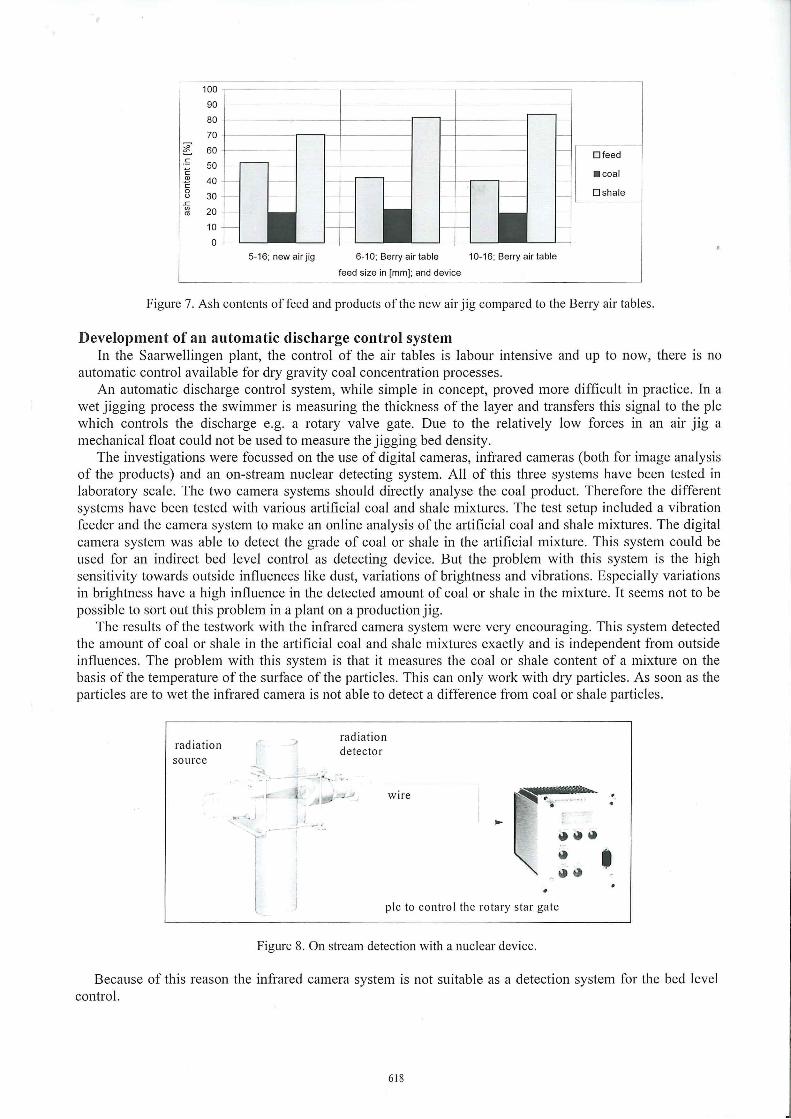
Figure 8. On stream detection with a nuclear device.
• Because of this reason the infrared camera system is not suitable as a detection system for the bed level
control.
618

The last tested system was a nuclear detecting device like shown in figure 8. This system consists of a nuclear source witch beams a constant nuclear radiation in one direction, a nuclear detector and a plc-controller. The more radiation is absorbed by material between the source and the detector the less radiation is detected. Shale absorbs about two times more radiation than coal. This system was tested by using clean coal and pure shale between source and detector. Both detected radiation values were used to calibrate the system. This calibration results in a linear function. In a distance of 1,2 meters between detector and source with air as medium about 120.000 counts per second radiation could be measured (clean coal results in 4000 counts, pure shale in 2000). This system is free of influences from outside and the surface moisture content of particles for detection has no bad effect.
After the system is calibrated the density of the heavy layer material inside the jig bed is measured. A reserve layer of high density material should remain over the discharge gate. As soon as the density rises over the setpoint, so that shale could be discharged through the overflow (the coal discharge) the rotary gate turns faster. On the other band when the system measures a density that is lower than the setpoint, which means coal could be discharged with the shale, the gate turns slower or stops.
This nuclear detection system turned out to be suitable as a detection device for an air jig bed level control system.
SETUP AND FULL SCALE TESTWORK WITH THE PRODUCTION JIG
Based on the results and experiences of the pilot air jig, the Gennan-based equipment manufacturing company Allmineral designed and constructed an industrial scale air jig, which can be seen in figure 9. The first commissioning was in August 2001 in Colorado/USA. The American coal mine was looking for a simple process to clean run of mine coal from tunnelling which was not processed and stockpiled before.
Figure 9. New developed air jig in production scale.
The feed enters through a rotary gate into the separation area to reduce the amount of dust. The discharge is equipped with an adjustable splitter and the amount of discharged heavy material (shale) is regulated by a second rotary gate. This air jig should be save to operate, provide high throughput and require low maintenance. The most impo1iant difference to pneumatic sorting aggregates that were used in the past should be an automatic discharge control system, a modular design and the possibility to react on changing feed quantities and qualities.
The automatic control system was equipped with a nuclear detection system, as shown in figure 9. This nuclear device uses a cobalt source on the one side of the jig bed and a detector which measures the radiation on the other side.
619

Results and experiences of füll scale testing of the new air jig After commissioning the air jig in Colorado füll scale testing sta1ied. The air jig is designed to process feed minus 50 mm. During the test work is was proven that 80 mm feed
can block some of the chutes or the discharge gate. The air jig can reduce the ash content of feed from roughly 35 % to values of 12 % to 19 % ash depending
on the density setpoint selected by the bed level controller. Likewise, material with ash contents of around 60 % was upgraded to clean coal with ash contents between 12 % to 25 %. The throughput of the air j ig was about 50 tons per meter width per hour. Figure 10 and 11 are representing some results of the air jig performance of different particle size ranges. There were nearly no intergrown particles in the run of mine coal and Figure 11 illustrates this. The density distribution is a line and not a curve . This simplified the separation on the air jig. '
.~
c CL> c 0 ü
..c (/) ro
100
90
80
Dfeed
•coal
Dshale
70 1------~---------~-----1
60 ~-~~~-=o--~~l~~-+-~~~-ri
50 _, ______ ,
40 -j------1
30
20
10
0 <1 5-1 10-5
-1-l -1-
16-10 22,4-16 31,5-22,4
feed s ize in [mm]
>31,5 sum
Figure 10. Ash contents of coal, feed and shale feeding run of 111ine coal Colorado/USA.
100 - >31,5 feed
90 • • • • • 31,5-10 feed
80 10-5 feed
70 >31,5-5 feed
~ 60 ....... >31,5 coal
.~ 50 -+-- 31,5-10 coal c :J 0 40 - - - __.._ 10-5 coal E ro
30 - -.- >31,5-5 coal
20 - >31,5 shale
10 31 ,5-10 shale
0 10-5 shale
<1,3 <1,5 <1,7 <1,9 <2 , 1 >31,5-5 shale
density in [g/cm3]
Figure 11. Density distribution of coal, feed and shale feeding run of mine coal Colorado/USA (The nu111bers in the legend are the different paiiicle size fractions in 111111).
The air jig is working better with bigger feed size. A sufficient coal cleaning is possible with a feed bigger in size than 5 mm. Coal bigger in size than 10 mm is processed perfectly.
620

To get better results processing smaller fractions it is much better to screen the coal and feed it separately. The overall yield of coal is 91 %.
lt is interesting to note there were several raining days during the setup in Colorado. Occasionally it was difficult to keep the chutes from plugging, but the screen bed never plugged. There were times when coal and refuse discharged as one agglomerated ball, but once the feed dried sufficiently separation began immediately.
The automatic bed density control system is very effective. Changing the density set-point results in almost immediate changes of the quality of product and refuse. The air jig is capable of handling quality changes of the feed as long as the volume maintains nearly constant. The current design of the air jig plant, utilizing stacking conveyors, can be operated with only one person. The air jig hasn't operated long enough to develop a maintenance history. The air jig plant can be supplied in a modular design . The development o'f an improved air jig is met, and the economic boundaries for processing coal are expanded.
Economic data of the air jig lt is estimated an air jig plant similar to the one shown in figure 10 including foundations, conveyors and
power can be constructed for under 10.000 US$ per ton per hour capacity. Therefore, depending on the cost of capital, and a mine's philosophy on manning and maintenance, the cost of operating an air jig plant could range from $1.00 to $2.00 per raw ton of feed. The new developed air jig can be supplied in a modular design.
SEPARATION OF THE FINE SIZE PARTICLES USING MAGNETIC SEPARATION
lt was not possible to process the fine fraction (minus 5 mm) sufficient with the air jig. To separate this fine fraction several dry operating high gradient magnetic separators have been tested. The best results were obtained with a magnetic roll separator produced by the German company Steinert. This magnetic separator is equipped with Neodymium steel boron magnets, the strongest permanent magnets industrially available. (Atesok 1999)
feed 1111.
magnetic roll
rnagnetic fraction (shale)
unm ag neti c frac tion (coa l)
Figure 12. Principle ofthe magnetic separation.
In figure 12 the principle of the magnetic separation is shown. The feed occurs over a vibration feeder on the belt. The shale fraction is weakly magnetic and the FeO-content of the sample is about 4 %. The shale particles are slightly deflected by the magnetic forces and can be recovered efficiently.
Results of the magnetic separation The ash contents of feed, coal and shale products from the test-work is illustrated in the figure 13. lt
represents the results of the magnetic separation feeding coal from the Saarwellingen plant. The feed size ranges are 0-5 mm. On the right side the black bar represents the ash content of a pure piece of coal and the grey bar the ash content of a pure piece of shale. This shows the best feasible sorting result.
More testwork has been done with different American and English coals. The results were similar.
621

The results are indicating that it is possible to efficiently reduce the ash content in the fine coal fractions by magnetic separation . The yield of coal feeding 0-5 mm is 62 %. For the best results, screening of the feed in narrow size fractions is necessary. The tests were done with a throughput of about 1,5 to 2 tons per meter width per hour. The ash content of the product increases with the increase of the throughput. lt is possible to reach a throughput of more than 3 ,5 tons per meter width per hour. This is a point where this separation starts getting economical. The ash content of the product can be varied between 13 % to 25 %, feeding Saarwellingen coal.
100 90 -
...... 80 ~ L
70 .:: - 60 c: Cl> 50 -c: 0 u 40
..c: 30 1/)
20 ca
10 0
CONCLUSIONS
0-2 2-4 4-5 0-5 oure
feed size in [mm]
Figure 13. Results of magnetic separation; Saarwellingen coal.
Dfeed
• coal
Dshale
Current state of the art in dry coal dressing is the Saarwellingen plant, which is actually technology of the 60 ' s. Its problems are low efficiency in the fine fraction -6 mm and the coarse fraction + 30 mm and a low overall throughput. The separation results in the medium size fractions between 6 and 30 mm are excellent.
A modern dry coal dressing plant has to overcome these problems, using different optimised processes for each size fraction as weil as automated process control systems. At the Department of Mineral Processing of the RWTH Aachen, different techniques have been tested: a new air jig for the coarse and medium size including automatic process control systems and high gradient magnetic separation for the fine size, with encouraging results.
In a combination of these separation technologies, efficient dry coal preparation is possible.
REFERENCES
Atesok, G„ Perek, K.T. and Dincer, H„ Reduction of Ash and Sulfur Contents of Low-Rank Turkish Semicoked Lignite by High Intensity Dry Magnetic Separation. Coal Preparation, 20, 179-190 ( 1999).
Frankland, S.C„ Dry benefication of coal, Department of trade and Industiy's Coal Research. England, (1995).
Groß, J. and Ditzler, H„ Trockenaufbereitung ballastreicher Steinkohle. Bundesministerium für Forschung und Technologie (BMFT), Aachen, (1982).
Güldenpfennig, M. and Löhr, K„ Sortierung vermischter Reststoffe gleicher Dichte auf dem Luftherd. Aufbereitungstechnik, 36(7), 314-320 (1995) .
Padberg, W„ Kohlenaufbereitung im Saarbergbau. Erzmetall, 42(11) 507-512. ( 1989). Schubert, H, Aufbereitung fester mineralischer Rohstoffe. VEB Deutscher Verlag für Grundstoffindustrie,
Leipzig, Germany, 92-119 (1995). Weitkämper, L„ Wotruba, H., .Pneumatic Dry Cleaning of Coal. In Proceedings of MEI Conferences
Magnetic, Electrical & Gravity Separation, Falmouth, England, (2001). Weiss, N.L. et al, SME Mineral Processing Handbook. American Institute of Mining, Metallurgical -and
Petroleum Engineers, Kingsport Press, New York, USA, 4/51-4/53 (1985).
622