Embed Size (px)
Citation preview
The development of a hybrid underwater microbiped robot
doi:10.1533/abbi.2006.0034
S. Guo1, Y. Okuda1, W. Zhang1, X. Ye2 and K. Asaka3
1Faculty of Engineering, Kagawa University, Hayashi-cho 2217-20, Takamatsu 761-0396, Japan2Automation College, Harbin Engineering University, 145 Nantong Street, Nangang District, Harbin, China3Kansai Research Institute, AIST, 1-8-31 Midorigaoka, Ikeda, Osaka 563-8577, Japan
Abstract: There has been a great demand, in the medical field and in industrial applications, for a novelmicro biped robot with multiple degrees of freedom that can swim smoothly in water or in aqueousmedium. The fish-like micro-robot studied is a type of miniature device that is installed with sensingand actuating elements. This article describes the new structure and motion mechanism of a hybrid typeof underwater micro-robot using an ion-conducting polymer film (ICPF) actuator, and discusses theswimming and floating characteristics of the micro-robot in water, measured by changing the voltagefrequency and the amplitude of the input voltage. Results indicate that the swimming speed of theproposed underwater micro-robot can be controlled by changing the frequency of the input voltage,and the direction (upward or downward) can be manipulated by changing the frequency of the electriccurrent applied and the amplitude of the voltage.
Key words: micro-robot, micro biped robot, micro-actuator, propulsion, ICPF actuator, propulsion,optimization.
INTRODUCTION
Intracavity intervention is expected to become increasinglypopular in the medical practice, both for diagnosis and forsurgery. Recently, many micro-robots have been devel-oped for various purposes owing to the advances of theprecise process technology, and further progress in thisfield is expected. There has been a great demand, in themedical field and in industrial applications, for a new typeof fish-like micro-robot that can swim smoothly in wateror in aqueous medium (Dario 1988; Special session onBiorobotics 1990; Maddock 1994). The fish-like micro-robot is a type of miniature device that is installed withsensing and actuating elements and can swim smoothly inwater or in aqueous medium, which can be used for in-pipeinspection and micro-surgery of blood vessel.
Recently, several types of fish-like micro-robots usingshape memory alloy, giant magnetostrictive alloy, piezo-electric and polymer actuators have been reported (Fukudaet al. 1991, 1994, 1995; Oguro et al. 1993; Mojarrad and
Corresponding Author:Shuxiang GuoFaculty of EngineeringKagawa University, Hayashi-cho 2217-20Takamatsu 761-0396, JapanTel: +81-87-864-2333; Fax: +81-87-864-2369Email: [email protected]
Shahinpoor 1997; Guo et al. 1998, 2005; Osada 1992).However there are some problems, such as compact struc-ture, low response, leaking electric current, safety in water,and so on. We aim to develop a type of fish-like micro-robotthat can swim smoothly in water or in aqueous medium.It has the characteristics of flexibility, is driven by a lowvoltage, and shows good response and safety in the body.Biomimetic fish-like propulsion using an ion-conductingpolymer film (ICPF) actuator as a propulsion tail fin for anunderwater micro-robot swimming structure in water oraqueous medium is developed. The ICPF actuator is madefrom a film of perfluorosulfonic acid polymer (Nafion 117,DuPont) chemically plated on both sides with platinum.In many aspects, the ICPF actuator is superior to the usualpolymer gel actuators; it has fast response, can be driven bylow voltage (about 1.5 V) in wet conditions without elec-trolysis, and is safe in the body and so on (Tadokoro et al.1998, 2000). The use of ICPF actuators now make it pos-sible to replicate the undulating motion of marine animalsin a more direct way (Guo et al. 2003, 2004, 2005c; Wanget al. 2006; Zhang et al. 2005a, 2005b, 2006). This articledescribes the structure and the mechanism of motion ofa novel underwater micro-robot having an ICPF actuator,and discusses the swimming ability of the micro-robot inwater. The characteristics of the underwater micro-robotare measured by changing the frequency (from 0.1 to 5 Hz)and amplitude (from 0.5 to 10 V) of the input voltage. Re-sults indicate that the swimming speed and the buoyancy
C© Woodhead Publishing Ltd 143 ABBI 2006 Vol. 3 No. 3 pp. 143–150
S. Guo, Y. Okuda, W. Zhang, X. Ye and K. Asaka
ICPF actuator
ICPF actuator (B)
Body (A)
Fin
Fin
Electrode
Electrode
(a) Structure of a tail
(b) Total structure
(c) Structure of micro biped robot with 1 DOF
(d) Structure of micro biped robot with multi DOF
Buoyancy adjuster (D)
ComLeft
Right
V+
V+
(C)
Lead wire
Lead wire
Lead wire Lead wire
Lead wire
Body
Body
ICPFactuator
ICPFactuator
ICPFactuator
ICPFactuator
ICPFactuator
ICPFactuator
Claw
Claw
Claw Claw
Supporter
Supporter
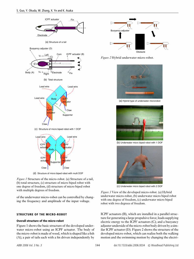
Figure 1 Structure of the micro-robot. (a) Structure of a tail,(b) total structure, (c) structure of micro biped robot withone degree of freedom, (d) structure of micro biped robotwith multiple degrees of freedom.
of the underwater micro-robot can be controlled by chang-ing the frequency and amplitude of the input voltage.
STRUCTURE OF THE MICRO-ROBOT
Overall structure of the micro-robot
Figure 1 shows the basic structure of the developed under-water micro-robot using an ICPF actuator. The body ofthe micro-robot is made of wood, which is shaped like a fish(A); a pair of tails each with a fin driven independently by
Buoyancy adjuster
Obstacle
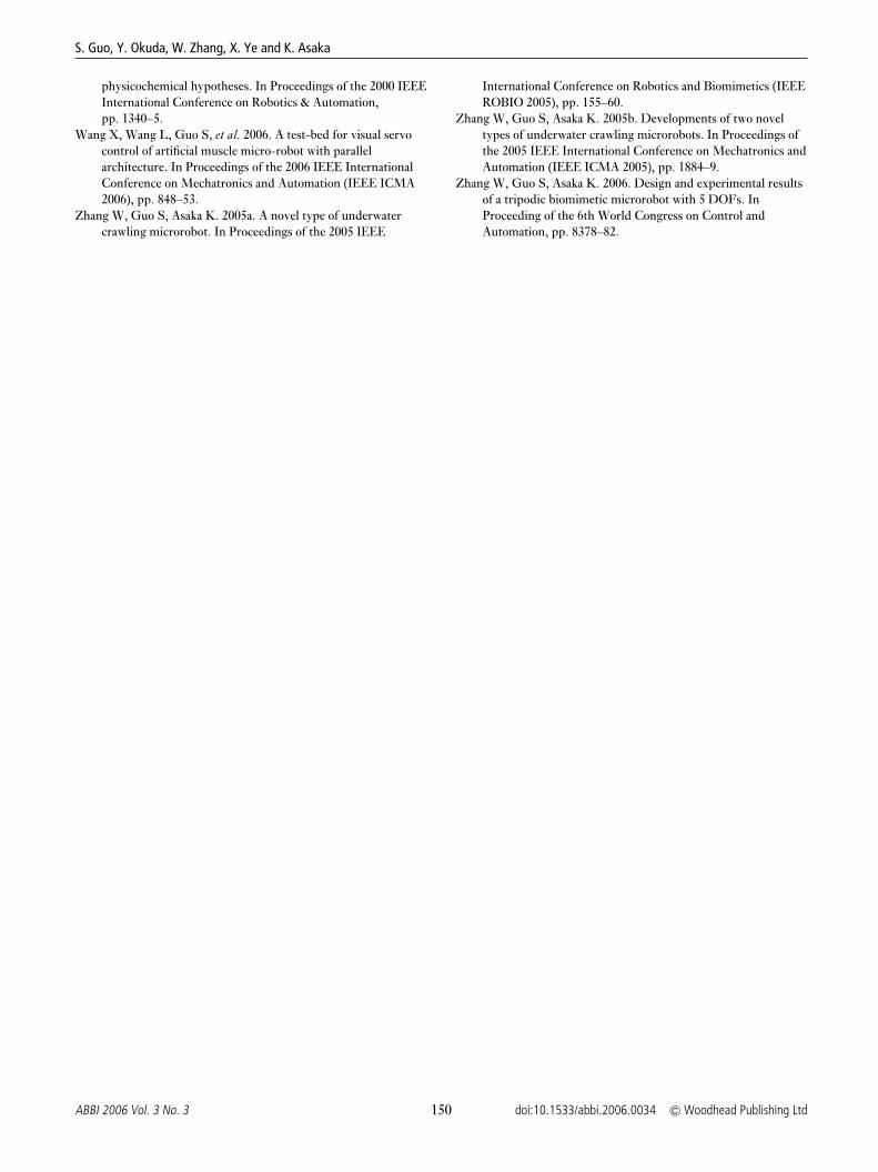
Figure 2 Hybrid underwater micro-robot.
(a) Hybrid type of underwater microrobot
(b) Underwater micro biped robot with 1 DOF
(c) Underwater micro biped robot with 2 DOF
Figure 3 View of the developed micro-robot. (a) Hybridunderwater micro-robot, (b) underwater micro biped robotwith one degree of freedom, (c) underwater micro bipedrobot with two degrees of freedom.
ICPF actuators (B), which are installed in a parallel struc-ture for generating a large propulsive force; leads supplyingelectric energy to the ICPF actuators (C); and a buoyancyadjuster underside of the micro-robot body driven by a sim-ilar ICPF actuator (D). Figure 2 shows the structure of thedeveloped micro-robot, which can realize both the walkingmotion and the swimming motion by changing the electri-
144ABBI 2006 Vol. 3 No. 3 doi:10.1533/abbi.2006.0034 C© Woodhead Publishing Ltd

The development of a hybrid underwater micro biped robot
Time (S)
Vol
tage
(V
)
T
V0
t1 t2
Figure 4 Driving electric voltage.
Table 1 Moving motion of the micro-robot
Forwarda Right turn Left turn
f 1 = f 2 f 1 > f 2 f 1 < f 2
a f 1: right ICPF actuator frequency; f 2: left right ICPF actuatorfrequency.
cal frequency. The photo of the developed micro-robot isshown in Figure 3.
ICPF actuator
The ICPF actuator is made from a film of perfluorosulfonicacid polymer (Nafion 117, DuPont) chemically plated onboth sides with platinum (of 0.003 mm thickness). It isknown as an ion-exchange membrane. It is a type of high-polymer gel actuator that works only in water and in wetconditions. The ICPF bends toward the anode when avoltage of about 1.5 V is applied onto its surfaces. Thedisplacement of the ICPF is proportional to the electricalvoltage input on its surface as the swelling of polymergels. The other characteristic of the ICPF actuator is thatwhen the frequency of the applied voltage is low, less than0.3 Hz, the water around the ICPF surface is electrolysed,so water blebs are generated on both sides of the ICPFsurface. As a result of this change in body volume, thebuoyancy of the micro-robot can be controlled. To drivethe fin for propulsion the ICPF actuator (0.2 × 3 × 15 mm)is cut in a strip, and in the buoyancy adjuster the ICPFactuator (0.2 × 4 × 6 mm) is used as shown in Figure 1.
MECHANISM OF MOTION OF THE MICRO-ROBOT
The developed micro-robot has two tails each with a findriven by an ICPF actuator as shown in Figure 1. Thefins are offset at a distance d, and driven independently byelectric voltage of frequencies f 1 and f 2, respectively, asshown in Figure 4. The motion of a fin can be described bya combination of two kinds of motion, feathering (motionin the direction parallel to the surface of water) and heaving(motion in the upward and downward directions). When aproper phase difference is established between heaving andfeathering, the fin generates an effective force, as shown inFigure 5. The propulsive force is the sum of drag force vec-tors in the direction of motion (Equation (1)). By changingthe frequencies f 1 and f 2 of the electric voltage appliedon the ICPF actuators, the micro-robot can be made to
ICPF actuator Fin
f 1 (Right)
f 2 (Left)
d PVForward
R
L
Figure 5 Mechanism of micro-robot using ICPF actuators.
Body
Lead wire
ICPF actuator
Wire
Figure 6 Adjusting mechanism of hybrid micro-robot.
Mg
F
P ∆ F
Figure 7 Floating mechanism of the micro-robot.
move in the forward, right turn, and left turn directions(Table 1).
The micro-robot has a solenoid and two permanentmagnets. It can change the body posture by adjusting theposition of the barycentre, as shown in Figure 6.
P = − 12 Cdρ A |Vk| Vk, (1)
where Cd is the drag coefficient based on the wetted surfacearea A, ρ is the density of water, and Vk is the speed in thedirection of motion.
The micro-robot has a buoyancy adjuster driven by anICPF actuator. The ICPF actuator has the characteristicthat when the frequency of the applied voltage is less than0.3 Hz, the water around the ICPF surface is electrolysed,so water blebs are generated both sides of the ICPF surface.As a result of this change in body volume, the floatage ofthe micro-robot can be controlled. The floating mechanismof the micro-robot is shown in Figure 7. We know that thefloatage of the micro-robot is
F = ρ × Va, (2)
where Va is the total volume of the micro-robot. At first,when the weight Mg is a bit higher than the floatage F,the micro-robot sinks downward in water. When the wateraround the ICPF surface is electrolysed, the generated blebadsorbs on both side of the ICPF actuator and it increasesthe total volume of the micro-robot by �V. It also increasesthe flotage by �F .
�F = ρ × �V. (3)
145C© Woodhead Publishing Ltd doi:10.1533/abbi.2006.0034 ABBI 2006 Vol. 3 No. 3

S. Guo, Y. Okuda, W. Zhang, X. Ye and K. Asaka
PCOscilloscope
Amplifierunit
Functiongenerator
Micro robot
Lasersensor
Figure 8 Measurement system.
We observed that the volume of the generated bleb canbe controlled by changing the frequency and the amplitudeof the applied voltage. When
�F = Mg − F, (4)
it stops sinking and gets suspended in water. When
�F > Mg − F, (5)
it begins to float upward; this happens when the frequencyof the applied voltage is less than 0.3 Hz. Electrolysis be-gins to be obvious, and the larger the amplitude of voltageapplied, the higher the volume of the bleb generated.
CHARACTERISTIC MEASUREMENT
Measurement system
A computer can control the electric voltage applied to theICPF actuators. The electrical current is measured by agalvanometer. The bending displacement of the fins atthe point of the front end is measured using a laser dis-placement sensor. The bending amplitude of the fins canbe measured in terms of the input voltage as shown inFigure 4. Measurement system is shown in Figure 8.
Characteristics of the fin
By using the measurement system shown in Figure 8,the following characteristics were measured. First, wemeasured the maximum displacement at the center pointof a fin in air by changing the frequency of the input voltage(Figure 4). Second, the maximum current is also measuredby changing the input voltage.
The experimental results are shown in Figures 9 and10, which show that the maximum displacement is in in-verse proportion to the frequency of the input voltage andthe maximum current is nearly proportional to the inputvoltage respectively.
PROTOTYPE FISH-LIKE MICRO-ROBOT
The prototype developed is shown in Figure 3. It is10 mm in width and 45 mm in length (body 15 mm without
0
0.1
0.2
0.3
0.4
0.5
0.6
0.7
0.8
0.9
1
0 1 2 3 4 5 6 7 8 9 10 11
Frequency (Hz)
Dis
plac
emen
t (m
m)
4V
3V
2V
(a) Displacement Measurement with Voltage
0
0.2
0.4
0.6
0.8
1
0 1 2 3 4 5 6 7 8 9 10 11Frequency (Hz)
Dis
plac
emen
t (m
m)
Rectangle
Sine
Triangle
(b) Displacement Measurement with Driving Wave
Figure 9 Experimental results of the displacement (in air).(a) Displacement measurement with voltage,(b) displacement measurement with driving wave.
0
0.05
0.1
0.15
0.2
0.25
Max
imum
Cur
rent
(A
)
0.2 0.4 0.6 0.8 1 1.2 1.4 1.6 1.8 2Voltage (V)
Figure 10 Maximum electric current (in air).
tail), as shown in Table 2. The body of the micro-robot ismainly made of wood as it is lightweight. In order to verifythe mechanism of the micro-robot, we carry out the swim-ming experiments in three directions with three degreesof freedom in water by changing the voltage frequency.Figure 11 shows the walking motion underwater. Figure 12shows the floating motion in the vertical direction for avoid-ing obstacles in the water by changing the buoyancy of themicro-robot in reaction.
146ABBI 2006 Vol. 3 No. 3 doi:10.1533/abbi.2006.0034 C© Woodhead Publishing Ltd

The development of a hybrid underwater micro biped robot
Figure 11 Walking motion underwater.
Table 2 Specifications of the prototypemicro-robot
Size 10 mm × 45 mmWeight 0.76 gMaterial WoodActuator ICPF (0.2 × 3 × 15)Power supply Electricity (e.g., 4 V,
0.15 A)
RESULTS
We carried out the swimming experiments of the pro-totype micro-robot using a measurement system shownin Figure 13. The propulsive forces for various frequen-cies were measured using a laser displacement sensor, anelectric balance, and a copper beam. The copper beamis soft enough to be bent by the propulsive force. Theelectric balance is used for evaluating the force. We alsomeasured the propulsion speed for various frequencies us-ing a high-speed camera. The average value of more than
Robot
Copper plate Laser displacement sensor
Fluid
Figure 13 Measurement system of propulsion.
0
0.5
1
1.5
2
2.5
3
3.5
4
4.5
5
5.5
6
0
0.5
1
1.5
2
2.5
3
3.5
4
0 0.5 1 1.5 2 2.5 3 3.5 4 4.5 5
Frequency
Speed
Propulsive force
Spe
ed (
10−3
m/s
)
Pro
puls
ive
forc
e (1
0−6 N
)
Figure 14 Experimental results (2.5 V).
20 measurements is used as the final test data. By changingthe frequency from 0.2 to 5 Hz at 2.5 input, the experi-mental results of the average propulsive force and the av-erage speed are shown in Figure 14. Experimental results
Figure 12 Floating motion for avoiding obstacles.
147C© Woodhead Publishing Ltd doi:10.1533/abbi.2006.0034 ABBI 2006 Vol. 3 No. 3

S. Guo, Y. Okuda, W. Zhang, X. Ye and K. Asaka
0
0.5
1
1.5
2
2.5
3
0 10 20 30 40 50 60 70 80 90 100
Frequency (10−2Hz)
Flo
atin
g sp
eed
(mm
/s)
6V
5V
4V
Figure 15 Experimental results of floating speed.
0
0.2
0.4
0.6
0.8
1
1.2
1.4
1.6
0 1 2 3 4 5 6 7Frequency (Hz)
Wal
king
spe
ed (
mm
/s)
2V3V4V
(b) Walking Speed with Voltage
0
0.2
0.4
0.6
0.8
1
1.2
1.4
1.6
0 1 2 3 4 5 6 7
Frequency (Hz)
Wal
king
spe
ed (
mm
/s)
RectangleSineTriangle
(b) Walking Speed with Driving Wave
Figure 16 Experimental results of the micro-robot with onedegree of freedom. (a) Walking speed with voltage,(b) walking speed with driving wave.
show that the speed can be varied from 1.3 to 5.21 mm/sby changing the voltage frequency. Figure 15 shows thefloating speed for the micro-robot by changing the voltagefrequency and amplitude of the input voltage.
Figures 16 and 17 show the experimental and theoreti-cal results, respectively, of the walking speed obtained bychanging the voltage frequency for the micro-robot withone degree of freedom. Figures 18 and 19 show, respec-tively, the experimental and the calculated values of thewalking speed by changing the voltage frequency for themicro-robot with two degrees of freedom. The results show
0
0.2
0.4
0.6
0.8
1
1.2
1.4
0 1 2 3 4 5 6 7
Frequency (Hz)
Wal
king
spe
ed (
mm
/s)
Experimental value
Theoretical value
Figure 17 Relationship between calculation results andexperimental results with one degree of freedom.
0.0
0.5
1.0
1.5
2.0
2.5
0.0 2.0 4.0 6.0 8.0 10.0 12.0 14.0 16.0 18.0 20.0
Frequency (Hz)
v (m
m/s
)1.5(V)
2.0(V)
2.5(V)
(a) Walking speed with voltage
0.0
0.5
1.0
1.5
2.0
2.5
0.0 2.0 4.0 6.0 8.0 10.0 12.0 14.0 16.0 18.0
Frequency (Hz)
v (m
m/s
)
Sine
Rectangle
Triangle
(b) Walking speed with driving wave
Figure 18 Experimental results of the micro-robot with twodegrees of freedom. (a) Walking speed with voltage,(b) walking speed with driving wave.
that by changing the voltage frequency and the amplitudeof the input voltage, we can control the walking speed forthe micro-robots, and the walking speed can be calculatedusing the displacement of the ICPF actuators and the volt-age frequency. It is very useful for the optimization designof the micro-robot.
148ABBI 2006 Vol. 3 No. 3 doi:10.1533/abbi.2006.0034 C© Woodhead Publishing Ltd

The development of a hybrid underwater micro biped robot
0.0
0.5
1.0
1.5
2.0
2.5
0.0 2.0 4.0 6.0 8.0 10.0 12.0 14.0 16.0 18.0
Frequency (Hz)
Wal
king
spe
ed (
mm
/s)
v = 0.0032f 3 − 0.104f 2 + 0.8724f − 0.1593
u = 0.0034f 3 − 0.1096f 2 + 0.9094f − 0.09
v (Experimental Value)
u (Theoretical Value)
Figure 19 Relationship between calculation results and experimental results with two degrees of freedom.
CONCLUSIONS
This article describes the structure and mechanism of mo-tion of a novel hybrid underwater micro-robot with ICPFactuators, and discusses the swimming and floating char-acteristics of the micro-robot in water. The mass center ofthe micro-robot can be controlled by an electromagneticactuator. So the floating motion in the vertical directionhas been realized easily. There are two pairs of fins, a masscenter adjuster and a floatage adjuster. Characteristic ofthe underwater micro-robot is measured by changing thevoltage frequency and amplitude of the input voltage. Theexperimental results indicate that the swimming speed ofthe proposed underwater micro-robot can be controlledby changing the frequency of input voltage, and the mov-ing direction (upward or downward) can be controlled bychanging the voltage amplitude and the frequency of theinput voltage.
On the basis of the experimental results, it was verifiedthat the proposed hybrid underwater micro biped robot canrealize swimming, walking, and floating motions, and therunning speed of the micro bipedal robot was controllableby changing the voltage amplitude and the frequency of in-put voltage. The micro-robot is expected to find industrialand medical applications.
REFERENCES
Bone Q, Marshall NB. 1982. Glasgow: Biology of Fishes. Blackieand Son.
Dario P. 1988. In Proceedings of the 1st IARP Workshop onMedical and Helthcare Robots, 23—24 June 1988, Ottawa,Canada, pp 789–92.
Fukuda T, Hosokai K, Arai F. 1991. Distributed type of actuator byshape memory alloy and its application to underwater mobilerobotic mechanism. In Proceedings of the IEEE Conferenceon Robotics and Automation, Nara, Japan, vol. 2, pp. 1316–32.
Fukuda T, Kawamoto A, Arai F, et al. 1994. Mechanism andswimming experiment of micro mobile robot in water. InProceedings of the IEEE Conference on Robotics andAutomation, May 1994, San Diego, CA, vol. 1, pp. 814–9.
Fukuda T, Kawamoto A, Arai F, et al. 1995. Steering mechanismof underwater micro mobile robot. In Proceedings of 1995IEEE Conference on Robotics and Automation, May 1995,Nagoya, Japan, vol. 1, pp. 363–8.
Guo S, Fukuda T, Asaka K. 2003. A new type of fish-likeunderwater microrobot. IEEE/ASME Trans Mechatronics,8: 136–41.
Guo S, Fukuda T, Kato N, et al. 1998. Development of underwatermicrorobot using ICPF actuator. In Proceedings of the 1998IEEE International Conference on Robotics and Automation,Leuven, Belgium, pp. 1829–34.
Guo S, Okuda Y, Asaka K. 2004. A novel type of underwater microbiped robot with multi DOF. In Proceedings of the 2004IEEE International Conference on Robotics & Automation,pp. 4881–6.
Guo S, Okuda Y, Asaka K. 2005c. Hybrid type of underwatermicro biped robot with walking and swimming motions. InProceedings of the 2005 IEEE International Conference onMechatronics and Automation (IEEE ICMA 2005), pp. 81–6.
Guo S, Sawamoto J, Pan Q. 2005. A novel type of microrobot forbiomedical application. In Proceedings of the 2005 IEEEInternational Conference on Intelligent Robotics and Systems(IROS 2005), pp. 1012–7.
Maddock L, Bone Q, Klehone J. 1994. Mechanics and Physiology ofAnimal Swimming. Cambridge: Cambridge University Press.
Mojarrad M, Shahinpoor M. 1997. Biomimetic robot propulsionusing polymeric artificial muscles. In Proceedings of 1997IEEE International Conference on Robotics and Automation,Albuquerque, NM, USA, pp. 2152–7.
Oguro K, Asaka K, Takenaka H. 1993. Polymer film actuatordriven by a low voltage. In Proceedings of 4th InternationalSymposium on Micro Machine and Human Science,pp. 39–40.
Osada Y, Okuzaki H, Hori H. 1992. A polymer gel of electricallydriven moiety. Nature 355: 242–4.
Special Session on Biorobotics. 1990. Proceedings of the 12thIEES/EMBS Conference, 1–4 November 1990, Philadelphia,PA, pp. 1942–1943.
Tadokoro S, Yamagami S, Takamori T. 1998. Development of adistributed actuation device consisting of soft gel actuatorelements. In Proceedings of the IEEE ICRA, pp. 2155–60.
Tadokoro S, Yamagami S, Takamori T. 2000. An actuatormodel of ICPF for robotic applications on the basis of
149C© Woodhead Publishing Ltd doi:10.1533/abbi.2006.0034 ABBI 2006 Vol. 3 No. 3
S. Guo, Y. Okuda, W. Zhang, X. Ye and K. Asaka
physicochemical hypotheses. In Proceedings of the 2000 IEEEInternational Conference on Robotics & Automation,pp. 1340–5.
Wang X, Wang L, Guo S, et al. 2006. A test-bed for visual servocontrol of artificial muscle micro-robot with parallelarchitecture. In Proceedings of the 2006 IEEE InternationalConference on Mechatronics and Automation (IEEE ICMA2006), pp. 848–53.
Zhang W, Guo S, Asaka K. 2005a. A novel type of underwatercrawling microrobot. In Proceedings of the 2005 IEEE
International Conference on Robotics and Biomimetics (IEEEROBIO 2005), pp. 155–60.
Zhang W, Guo S, Asaka K. 2005b. Developments of two noveltypes of underwater crawling microrobots. In Proceedings ofthe 2005 IEEE International Conference on Mechatronics andAutomation (IEEE ICMA 2005), pp. 1884–9.
Zhang W, Guo S, Asaka K. 2006. Design and experimental resultsof a tripodic biomimetic microrobot with 5 DOFs. InProceeding of the 6th World Congress on Control andAutomation, pp. 8378–82.
150ABBI 2006 Vol. 3 No. 3 doi:10.1533/abbi.2006.0034 C© Woodhead Publishing Ltd

International Journal of
AerospaceEngineeringHindawi Publishing Corporationhttp://www.hindawi.com Volume 2010
RoboticsJournal of
Hindawi Publishing Corporationhttp://www.hindawi.com Volume 2014
Hindawi Publishing Corporationhttp://www.hindawi.com Volume 2014
Active and Passive Electronic Components
Control Scienceand Engineering
Journal of
Hindawi Publishing Corporationhttp://www.hindawi.com Volume 2014
International Journal of
RotatingMachinery
Hindawi Publishing Corporationhttp://www.hindawi.com Volume 2014
Hindawi Publishing Corporation http://www.hindawi.com
Journal ofEngineeringVolume 2014
Submit your manuscripts athttp://www.hindawi.com
VLSI Design
Hindawi Publishing Corporationhttp://www.hindawi.com Volume 2014
Hindawi Publishing Corporationhttp://www.hindawi.com Volume 2014
Shock and Vibration
Hindawi Publishing Corporationhttp://www.hindawi.com Volume 2014
Civil EngineeringAdvances in
Acoustics and VibrationAdvances in
Hindawi Publishing Corporationhttp://www.hindawi.com Volume 2014
Hindawi Publishing Corporationhttp://www.hindawi.com Volume 2014
Electrical and Computer Engineering
Journal of
Advances inOptoElectronics
Hindawi Publishing Corporation http://www.hindawi.com
Volume 2014
The Scientific World JournalHindawi Publishing Corporation http://www.hindawi.com Volume 2014
SensorsJournal of
Hindawi Publishing Corporationhttp://www.hindawi.com Volume 2014
Modelling & Simulation in EngineeringHindawi Publishing Corporation http://www.hindawi.com Volume 2014
Hindawi Publishing Corporationhttp://www.hindawi.com Volume 2014
Chemical EngineeringInternational Journal of Antennas and
Propagation
International Journal of
Hindawi Publishing Corporationhttp://www.hindawi.com Volume 2014
Hindawi Publishing Corporationhttp://www.hindawi.com Volume 2014
Navigation and Observation
International Journal of
Hindawi Publishing Corporationhttp://www.hindawi.com Volume 2014
DistributedSensor Networks
International Journal of


![CONTENTS - ICPF UK fileCONTENTS THE LORD JESUS IS OUR ONLY HOPE Mary Mathew 06 ... Øn¬ Ab®p Xcphm≥ At]£n°p∂p. RßfpsS hnemkw: COLLEGIA TE FISHERMAN, Board of Publications,ICPF,](https://img.dokumen.tips/doc/110x75/5b5901927f8b9aec628d253b/contents-icpf-uk-the-lord-jesus-is-our-only-hope-mary-mathew-06-on-abp.jpg)
![Research Article CompaRob: The Shopping Cart Assistance Robotdownloads.hindawi.com/journals/ijdsn/2016/4781280.pdf · 2016. 2. 7. · e study carried out in [ ] concludes that elder](https://img.dokumen.tips/doc/110x75/5fe03030970b8e28d221ece3/research-article-comparob-the-shopping-cart-assistance-2016-2-7-e-study-carried.jpg)