Embed Size (px)
Citation preview

The design and physical modelling of deployable structures based on curved-line folding
A. Vergauwen, N. De Temmerman & S. Brancart ae-LAB, Department of Architectural Engineering, Vrije Universiteit Brussel (VUB), Belgium
Abstract
Curved-line folding is the act of folding paper along a curved crease pattern in order to create a 3D shape, using the combination of folding (plastic deformation) and bending (elastic deformation). Up until now, the use of curved-line folding in architecture has been limited to static applications only, such as metal sculptures or façade panels. However, the elastic deformations that occur when a flat sheet is forced into a curved shape can produce an interesting transformation process. The elastic deformation of one area of the sheet results in the folding and bending of adjacent surface areas as the internal forces and moments are transferred through the curved creases. This paper explains how this behaviour can be used for the design of deployable structures finding their application in the context of adaptive shading. Through the analysis of various crease patterns and the fabrication of small scale models, some important design parameters are defined. This paper demonstrates how the choice of the composition of the crease pattern, the curvature of the creases and the Length–Thickness Ratio affect the resulting kinetic system. The outcome of the analysis is useful for the design of deployable structures based on curved-line folding. Keywords: curved-line folding, curved-crease folding, deployable structures, pliable structures, scale models, kinematic shading.
Mobile and Rapidly Assembled Structures IV 145
doi:10.2495/MAR140121
www.witpress.com, ISSN 1743-3509 (on-line) WIT Transactions on The Built Environment, Vol 136, © 2 014 WIT Press
1 Introduction
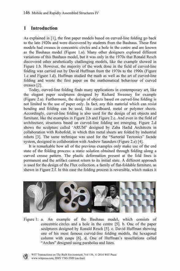
As explained in [1], the first paper models based on curved-line folding go back to the late 1920s and were discovered by students from the Bauhaus. These first models had creases in concentric circles and a hole in the centre and are known as the Bauhaus model (Figure 1.a). Many other designers explored different variations of this Bauhaus model, but it was only in the 1970s that Ronald Resch discovered other aesthetically challenging models, like the example showed in Figure 1.b. However, the majority of the work done in the field of curved-line folding was carried out by David Huffman from the 1970s to the 1990s (Figure 1.c and Figure 1.d). Huffman studied the math as well as the art of curved-line folding and wrote the first paper on the mathematical behaviour of curved creases [2]. Today, curved-line folding finds many applications in contemporary art, like the elegant paper sculptures designed by Richard Sweeney for example (Figure 2.a). Furthermore, the design of objects based on curved-line folding is not limited to the use of paper only. In fact, any thin material which can resist bending and folding can be used, like cardboard, metal or polymer sheets. Accordingly, curved-line folding is also used for the design of art objects and furniture, like the examples in Figure 2.b and Figure 2.c. And even in the field of architecture, structures based on curved-line folding are emerging. Figure 2.d shows the sculpture called ‘ARUM’ designed by Zaha Hadid Architects in collaboration with Robofold, in which thin metal sheets are folded by industrial robots [3]. The same technique was used for the “Sartorial Tectonics” facade system, designed in collaboration with Andrew Saunders (Figure 2.e) [4]. It is remarkable how all of the previous examples only make use of the end state of the folding process: a static solution obtained through folding along a curved crease pattern. The plastic deformation present at the fold lines is permanent and the artifact cannot return to its initial state. A different approach is used for the design of the Flux collection, a family of flat-foldable furniture, as shown in Figure 2.f. In this case the folding process is reversible, which makes it
Figure 1: a. An example of the Bauhaus model, which consists of concentric circles and a hole in the centre [5]. b. One of the paper sculptures designed by Ronald Resch [5]. c. David Huffman showing one of his most famous curved-line folding models, the hexagonal column with cusps [6]. d. One of Huffman’s tessellations called “Arches” designed using parabolas and lines.
146 Mobile and Rapidly Assembled Structures IV
www.witpress.com, ISSN 1743-3509 (on-line) WIT Transactions on The Built Environment, Vol 136, © 2 014 WIT Press

Figure 2: a. One of the many paper sculptures designed by Richard Sweeney. b. ‘Sit’, designed by Andreas Lund is a stackable stool in mouldedplywood [7]. c. A coffee table designed by Gregory Epps made out of curved-folded metal. d. ‘ARUM’ a metal sculpture designed by Zaha Hadid Architects in collaboration with Robofold [8]. e. The “Sartorial Tectonics” facade system, designed in collaboration with Andrew Saunders [4]. f. A demonstration of the Fluxx chair, which is part of a family of flat-foldable furniture [9].
possible to use the initial state for compact stacking and the folded end state as a chair or table. Although this approach takes into account the transformation process from a flat state to the folded end state, the intermediate states have no real function. The authors of this paper go one step further, by investigating how these intermediate states can be used for applications which require a continuous folding process.
2 Deployable structures based on curved-line folding
2.1 Bending-active kinetics
The transformation process of a surface with curved creases is quite complex. Schleicher describes curved-line folding as follows: ‘As one surface area of the element is elastically deformed this subsequently results in the deformation of the adjacent surface areas. As a result, the elastic deformations due to the bending of the paper can be applied as a ‘form-generating strategy’ [10]. Figure
Mobile and Rapidly Assembled Structures IV 147
www.witpress.com, ISSN 1743-3509 (on-line) WIT Transactions on The Built Environment, Vol 136, © 2 014 WIT Press

3 shows how the elastic deformation of the paper model’s central area, generated by pushing the ends towards the centre, forces the adjacent areas to fold inwards. The stored elastic energy in the deformed model can be used to return to the initial state, which makes the transformation reversible. In [10] this behaviour is compared to the principles of bending-active structures. ‘The object’s or systems’ deformation sequence is defined by taking into consideration geometrical relationships as well as coupled internal forces that cause the motion or are responsible for the resulting transformation. This relationship can be used to build up a cascading deformation movement or to gear the transmission of acting forces and moments.’ This principle is defined as bending-active kinetics and shows great potential for application in the design of adaptive façade shading systems.
2.2 Design of adaptive façade shading systems based on curved-line folding
As explained in [11], recent technological innovations encourage the development of climate adaptive (or responsive) building envelopes, which have the ability to maintain optimized configurations relative to changing conditions. Since the control of solar radiation and daylight has a major influence on the energy efficiency and comfort in buildings, architects and engineers are starting to experiment with adaptive façade shading systems. As they initially started with the actuation of traditional shading components like louvers and lamellas, today totally new kinematic designs are emerging. In this context, the principle of bending-active kinetics peculiar to curved-line folding shows great potential for application in adaptive façade shading systems. The application of curved-line folding principles for the design of such shading devices, can offer new aesthetic opportunities for the design of building envelopes. As an example, Figure 4 shows the conceptual design of a façade with adaptive shading elements based on curved-line folding. Three different phases of the folding process are illustrated.
Figure 3: The element is actuated by pushing the endpoints of the four legs to the centre of the element [11].
148 Mobile and Rapidly Assembled Structures IV
www.witpress.com, ISSN 1743-3509 (on-line) WIT Transactions on The Built Environment, Vol 136, © 2 014 WIT Press

Figure 4: Conceptual design of a façade with adaptive shading elements based on curved-line folding [12].
3 Analysis of deployable structures based on curved-line folding through small scale models
Not all curved-crease patterns generate a proper bending-active kinetic system. The challenge lies in designing the crease pattern in such a way that during the entire folding process an equilibrium shape is maintained and that the number of DOF is limited. In order to define some design parameters, the authors of this paper experimented with various small scale models. The models were made using polypropylene sheets because of its adequate material properties. It is a flexible material with a good resistance to fatigue, which makes it possible to create living hinges. As a result, the boundaries are cut and the creases are engraved using laser cut technology. Through the design and testing of various curved-line folding models, the authors were able to define design parameters which are important to take into account when designing deployable structures based on curved-line folding.
3.1 Composition and geometry of the creases
An exploration of numerous small scale models with various curved-crease patterns showed that in order to have a bending-active effect, the composition of the creases and their geometry plays an important role. Figure 5 gives an overview of various types of symmetric crease patterns which generate a bending-active kinetic system. The creases are represented by dashed lines and the segments indicated in bold represent the constrained boundary segments. When forces are applied on these segments, the circumscribed surface area is bent and the adjacent surface areas transform accordingly. In the horizontal direction, the patterns are arranged according to the number of creases used in the composition. The table stops at four, but of course patterns with a higher number of creases can be used. However, a higher number of creases results in a more complicated folding process, a higher number of boundary segments and therefore, a more complex actuation system. In the vertical direction a division is made based on the curve properties (convex, concave or with inflection points) and the composition (translation or reflection). By studying the small scale models of all these types of crease patterns some useful observations were made, as explained in the next paragraphs.
Mobile and Rapidly Assembled Structures IV 149
www.witpress.com, ISSN 1743-3509 (on-line) WIT Transactions on The Built Environment, Vol 136, © 2 014 WIT Press

3.1.1 Symmetric crease patterns based on the reflection of curves The first row in figure 5 shows symmetric crease patterns with a concave central area. These kinds of patterns generate a bending-active kinetic system with a big folding motion. Relative small displacements of the boundary segments towards the center of the model generate a deployment with a folding range of about 90 degrees, as demonstrated in Figure 6.c and Figure 6.d. As a result, an actuation system is needed which allows a uniform displacement in all of the constraint segments. The reversibility of the models is very high. The folded structure wants to go back to the initial (almost) flat state at all times. This is a quality which can be used in the design of the actuation system. The third row in figure 5 shows symmetric crease patterns with a convex central area. Similar to the patterns with a concave central area, a bending-active kinetic system with a big folding motion is produced. However, in order to control the deployment of the system, moment forces should be applied in the neighboring zones of the constrained segments of the central surface area, as shown in Figure 6.a and Figure 6.b. As a result, the deployment of this type of crease pattern requires a more complex actuation system, especially when the number of creases augments. The reversibility of the system is rather weak. A moment force in the opposite direction is needed in order to fold the model back to its initial state. In both of the previous cases the crease patterns generate a symmetric deployment. All the creases are used as purely valley or mountain folds and all the adjacent surface areas deploy in the same direction. However, when a composition with a mixed concavity is used, this is no longer the case. The adjacent surface areas fold in a different direction, depending on whether they are bounded by a mountain or a valley fold. As a result, the application as a deployable structure for adaptive shading seems less evident for this type of crease pattern. Additionally, the actuation becomes more complex due to the fact that the displacements and/or moments needed to control the deployment can vary depending on the zone of the central area. An example of such a crease pattern composed of respectively three and four creases is presented in the second row of Figure 5. Crease patterns obtained through the reflection of curves with an inflection point are showed in the fourth row of Figure 5. The deployable systems generated with this type of crease pattern are characterized by surfaces which contain transitions from convex to concave zones. Similar to the patterns with a concave or convex central area, a bending-active kinetic system with a big folding motion can be generated. However, the deformation of the central surface area needed to transfer the movement to the adjacent surfaces is much higher, as demonstrated in Figure 6.e and Figure 6.f. Furthermore, it is not obvious to find crease patterns of this type, composed of more than two creases, which generate a deployable system with bending active properties. However, when two curves with an inflection point are combined with a convex or concave curve, a kinetic system can be obtained, as shown in Figure 5. Since a combination of mountain and valley folds is required, some surface areas will
150 Mobile and Rapidly Assembled Structures IV
www.witpress.com, ISSN 1743-3509 (on-line) WIT Transactions on The Built Environment, Vol 136, © 2 014 WIT Press
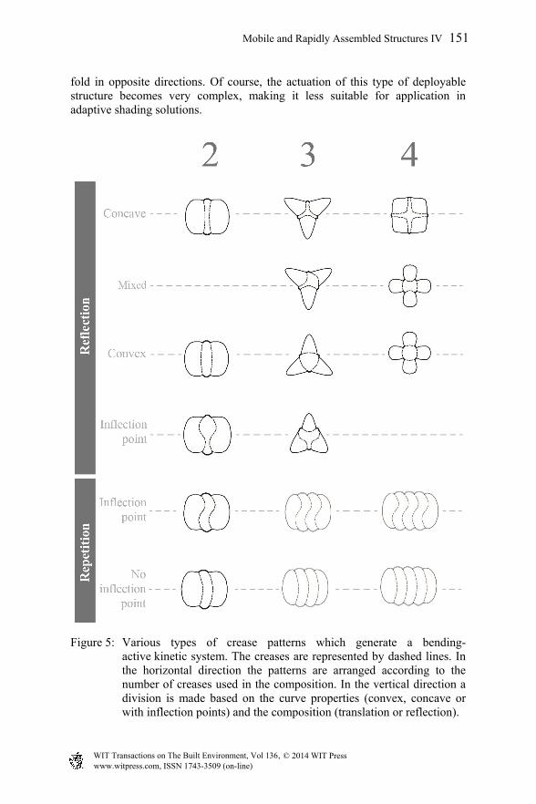
fold in opposite directions. Of course, the actuation of this type of deployable structure becomes very complex, making it less suitable for application in adaptive shading solutions.
Figure 5: Various types of crease patterns which generate a bending-active kinetic system. The creases are represented by dashed lines. In the horizontal direction the patterns are arranged according to the number of creases used in the composition. In the vertical direction a division is made based on the curve properties (convex, concave or with inflection points) and the composition (translation or reflection).
Mobile and Rapidly Assembled Structures IV 151
www.witpress.com, ISSN 1743-3509 (on-line) WIT Transactions on The Built Environment, Vol 136, © 2 014 WIT Press

3.1.2 Symmetric crease patterns based on the repetition of curves The last two rows in Figure 5 show crease patterns obtained by the repetition of curves with and curves without inflection points. When the pattern consists of 2 creases only, a bending-active kinetic system can be obtained. By bending the central surface, the forces and moments are transmitted to the adjacent surfaces which results in a folding motion. However, when more than 2 creases are used, more than one surface are needs elastic deformations in order to fold the whole system to a more compact state. As a result, the system loses its bending-active properties and behaves more like a mechanism. In Figure 5 these patterns are presented in a light-colored way.
Figure 6: Pictures showing the folding process of various crease patterns, with the open state on top and the folded state on the bottom.
3.1.3 Asymmetric crease patterns Of course, a lot more deployable systems can be generated when asymmetric crease patterns are used. However, due to the asymmetric composition of the pattern, the deployment of the adjacent surface areas, as well as the actuation forces and/or moments are also asymmetric. As a result, it is more difficult to control the system and the design of an appropriate actuation system can become really complex.
3.2 The Length–Thickness Ratio (LTR)
Another parameter affecting the folding behavior, in addition to the composition of the crease pattern, is the ratio between the length of the creases and the thickness of the material, defined by the authors as the Length–Thickness Ratio (LTR) of the system. To have an idea about the effect of the LTR on the stiffness of the structure and the forces needed for the deployment, the authors manufactured a series of small scale models in polypropylene of the type shown in Figure 6.a and Figure 6.b. By systematically adapting the scale of the same crease pattern in relation to polypropylene sheets with a thickness of 0.5, 0.8, 1.2
152 Mobile and Rapidly Assembled Structures IV
www.witpress.com, ISSN 1743-3509 (on-line) WIT Transactions on The Built Environment, Vol 136, © 2 014 WIT Press

or 1.8 mm, a series of 12 small scale models with a LTR going from 135 to 535 was obtained. By manually folding each model the stiffness as well as the force needed for the deployment was evaluated by the authors. The results are showed in Table 1. It is important to underline that these findings are not based on measured data, but solely on the experience of the authors when folding the models by hand.
Table 1: The effect of the Length–Thickness ratio on the stiffness of the structure and the actuation force needed for deployment. These results are obtained by manually folding each model.
When the LTR is higher than 400, the structure is very stiff and high forces are needed to fold the structure. Furthermore, the deployable system loses its reversibility, meaning that the elastic energy stored in the deformed model is not enough to return to the initial state. When the LTR is lower than 300, the structure is very flexible and the forces needed to fold the structure are low. The system maintains its reversibility, meaning that the deformed model always wants to return to the initial state. However, the structure has a very low stiffness, which is a drawback in the context of adaptive shading systems. The models with a LTR between 300 and 400 have a good balance between the stiffness of the structure and the forces needed for the deployment. Additionally, the transformation is reversible.
3.3 Curvature of the creases
As explained in [11] the curvature of the creases has an important influence on the folding behavior. Through the fabrication of a series of small scale models made from polypropylene sheets, the following observations were made. Crease patterns containing curves with a high curvature require larger displacements combined with lower actuation forces. A low curvature, on the other hand,
Length between
endpoints of
crease
Thickness of
Polypropylene
sheet
LTR Stiffness Actuation force
243 1,8 135 Very high Very high
288 1,8 160 Very high Very high
168 0,8 210 High High
282 1,2 235 High High
228 0,8 285 High High
558 1,8 310 Medium Medium
268 0,8 335 Medium Medium
288 0,8 360 Medium Medium
205 0,5 410 Low Low
230 0,5 460 Low Low
242,5 0,5 485 Very low Very low
267,5 0,5 535 Very low Very low
Mobile and Rapidly Assembled Structures IV 153
www.witpress.com, ISSN 1743-3509 (on-line) WIT Transactions on The Built Environment, Vol 136, © 2 014 WIT Press

requires small displacements and higher forces (Figure 7). These findings correlate with the results of the tests on a curved-line folding element through FE simulation in [10].
Figure 7: An overview of the relationship between the curvature of the creases and the folding behavior, the range of intermediate states and the actuation forces and displacements [11].
4 Conclusions
The principles of curved-line folding can be used to create bending-active kinetic systems. When one surface area is bent, the forces and moments are transmitted to the adjacent surface areas, which results in a folding motion. However, not all curved-crease patterns produce a bending-active kinetic system. Through the analysis of various crease patterns and the fabrication of small scale models, some important design parameters have been defined. The first parameter is the composition and the geometry of the crease pattern, which has an influence on the complexity of the actuation system, the folding directions, the reversibility of the system and, of course, the folded 3D shape. A table which gives overview of different types of crease patterns is provided in Figure 5, and is a very useful tool in the early design stages. The Length–Thickness Ratio, on the other hand, gives the designer an idea about the ratio between the length of the curves and the thickness of the material. Experiments with different physical models showed that the LTR should remain in a certain range in order to have a good balance between the stiffness of the structure and the forces needed for the deployment. This range is dependent on the geometry of the pattern, and was defined only for one specific crease pattern in this paper. A next step would be to define the LTR’s for the other types of crease patterns and add this information to the table in Figure 5. Another important design parameter is the curvature of the creases in the pattern. Experiments with various small scale models showed that crease patterns
154 Mobile and Rapidly Assembled Structures IV
www.witpress.com, ISSN 1743-3509 (on-line) WIT Transactions on The Built Environment, Vol 136, © 2 014 WIT Press

containing curves with a high curvature require larger displacements combined with lower actuation forces, whereas a low curvature requires small displacements and higher forces. As a result, the transformation process can be manipulated by adjusting the curvature of the creases. Although the findings in this paper are based on observations made by manually folding small scale models, they do give a first impression on the challenges and qualities of deployable structures based on curved-line folding. References
[1] Demaine, E.D., Demaine, M.L., Koschitz, D. and Tachi, T., Curved Crease Folding a Review on Art, Design and Mathematics, Proceedings of the IABSE-IASS Symposium: Taller, Longer, Lighter, London, UK, 2011.
[2] Huffman, D., Curvature and creases: A primer on paper, IEEE Transactions on computers, 1976.
[3] RoboFold – Make, http://www.robofold.com/make_consultancy_detail_ 02.html.
[4] Bustler: RoboFold nominated for ‘Emerging Design Studio’ at the ICON Magazine Awards 2013, http://www.bustler.net/index.php/article/ robofold_nominated_for_emerging_design_studio_at_the_icon_magazine_awards_2/.
[5] History of Curved-Crease Sculpture, http://erikdemaine.org/curved/ history/.
[6] Demaine, E.D., Demaine, M.L., and Koschitz, D., Reconstructing David Huffman’s legacy in curved-crease folding, Origami 5: Fifth International Meeting of Origami Science, Mathematics, and Education, 2011.
[7] Andreas Lund design, http://andreaslund.dk/indexmain.php?p=furniture &s=10&productname=Sit.
[8] Venice Architecture Biennale. Design Zaha Hadid Architects, http://www.zaha-hadid.com/design/contribution-to-2012-venice-biennale-theme-%E2%80%98common-ground%E2%80%99/.
[9] Flux chair, http://www.fluxfurniture.com/product/flux-chair/. [10] Schleicher, S., Lienhard, J., Poppinga, S., Masselter, T., Speck, T., and
Knippers, J., Adaptive façade shading systems inspired by natural elastic kinematics, Proceedings of the International Conference on Adaptive Architecture, London, 2011.
[11] Vergauwen, A., Alegria Mira, L., Roovers, K., and De Temmerman, N., Parametric design of adaptive shading elements based on Curved-line Folding, Proceedings of the First Conference Transformables 2013, Seville, Spain, 2013.
[12] De Temmerman, N., Roovers, K., Alegria Mira, L., Vergauwen, A., Koumar, A., Brancart, S., De Laet, L., and Mollaert, M., Engineering Lightweight Transformable Structures, Proceedings of the International Conference on Adaptation and Movement in Architecture, Toronto, Canada, 2013.
Mobile and Rapidly Assembled Structures IV 155
www.witpress.com, ISSN 1743-3509 (on-line) WIT Transactions on The Built Environment, Vol 136, © 2 014 WIT Press