Embed Size (px)
Citation preview

The CWDM Fiber Primer
1 | P a g e
The CWDM Fiber Primer Steve Russell, LYNX Technik Inc.
Last Updated: September, 2010

The CWDM Fiber Primer
2 | P a g e
(This page is intentionally blank)

The CWDM Fiber Primer
3 | P a g e
The CWDM Fiber Primer In our first paper “A Fiber Primer” we learned that the use of fiber optic connectivity for point to point applications is fairly simplistic, using a single unidirectional connection between two locations over a dedicated fiber link. However, in some installations it is desirable to make better use of the fiber cable assets and combine multiple signals into a single bidirectional fiber link. For this we use what’s called CWDM.
Typically, CWDM is a technology used to transport multiple signals between distant locations over single fiber connections. This leverages the utilization and therefore the relative cost of the long distance fiber cable links. However, with HDTV and the increasing bandwidths required for video production (3Gbit) and new 3D markets rapidly evolving (which makes extensive use of 3Gbit SDI in the production environment) we see fiber connectivity increasingly taking the place of traditional copper (electrical) connections within facilities. As this evolution continues and more and more dedicated unidirectional “point to point” fiber connections are consumed, then an “in house” CWDM solution is the logical next step to better utilize the facilities existing fiber cable assets.
What is CWDM? CWDM refers to Coarse Wavelength Division Multiplexing, a process of combining multiple wavelengths (multiple signals) into a single fiber optic cable. As different optical wavelengths can co-exist in a fiber cable without any interference to each other, then theoretically the process of combining multiple signals into a cable is only limited by the spectral characteristics of the fiber cable and number of wavelengths used. However, in practical terms there is a limit to what can be achieved.
In 2002 the ITU standardized the wavelengths which can be used with CWDM to 18 wavelengths from 1270nm to 1610nm with a channel spacing of 20nm (ITU-T G.692.2). Therefore, the maximum
number of signals which can be used in a CWDM fiber system is 18. (See below)
1270nm
1290nm
1310nm
1330nm
1350nm
1370nm
1390nm
1410nm
1430nm
1450nm
1470nm
1490nm
1510nm
1530nm
1550nm
1570nm
1590nm
1610nm
Wavelength1250 nm 1620 nm
O-BAND E-BAND S-BAND C-BAND L-BAND
CWDM Wavelength Grid as Specified by ITU-T G694.2
The CWDM Fiber Primer
4 | P a g e
There is also a technology called DWDM, (Dense Wavelength Division Multiplexing) which uses a much narrower channel spacing. Therefore many more wavelengths are supported. Because of the very narrow channel spacing used for DWDM, extremely stable precision lasers are required which have to be temperature controlled to prevent any drift. This increases cost and complexity considerably, and is currently only practical for very long haul applications between distant locations. DWDM is commonplace in the telecommunications industry.
WDM Technology
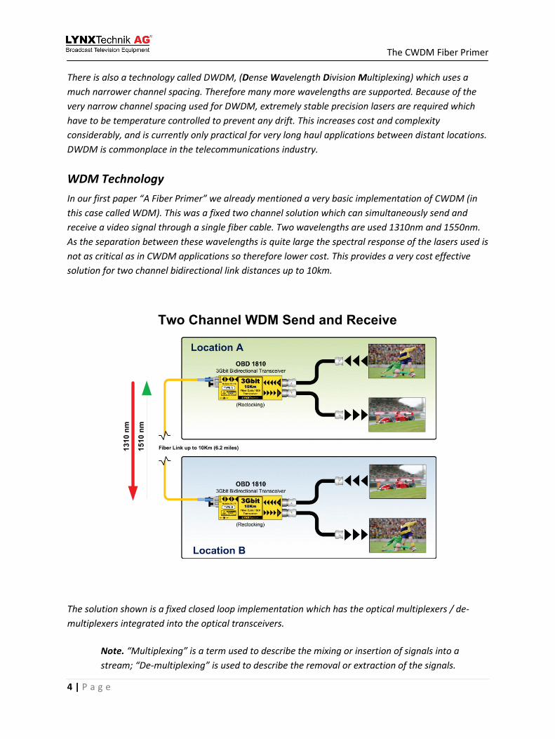
In our first paper “A Fiber Primer” we already mentioned a very basic implementation of CWDM (in this case called WDM). This was a fixed two channel solution which can simultaneously send and receive a video signal through a single fiber cable. Two wavelengths are used 1310nm and 1550nm. As the separation between these wavelengths is quite large the spectral response of the lasers used is not as critical as in CWDM applications so therefore lower cost. This provides a very cost effective solution for two channel bidirectional link distances up to 10km.
1310
nm
1510
nm
Two Channel WDM Send and Receive
The solution shown is a fixed closed loop implementation which has the optical multiplexers / de-multiplexers integrated into the optical transceivers.
Note. “Multiplexing” is a term used to describe the mixing or insertion of signals into a stream; “De-multiplexing” is used to describe the removal or extraction of the signals.

The CWDM Fiber Primer
5 | P a g e
CWDM Building Blocks There are two basic building blocks to a CWDM system
CWDM Fiber Transmitters – CWDM transmitters are specifically designed with a narrow spectral response (peaks) as the channel separation is quite small (20nm) so it’s important to make sure the fiber transmitters in the solution you are considering are “CWDM compatible”. The manufacturer usually provides a selection of wavelengths to choose from. In most cases you will find a manufacturer will offer 16 wavelength selections. LYNX Technik offers all 18 wavelengths supplied as optional Fiber SFP “stick” sub modules. Which can be readily installed, removed and swapped using the sockets provided.
Optical Multiplexers / De-multiplexers – These units are required to multiplex and de-multiplex the various CWDM wavelengths onto a single fiber link. These units are normally passive in operation (requiring no power) and each specific I/O port will be designated for use with a particular wavelength. (The LYNX Technik yellobrik OCM 1892 unit is shown below)
LYNX Yellobrik OCM 1892 – 9 Channel CWDM Optical MUX/DEMUX

The CWDM Fiber Primer
6 | P a g e
For the yellobrik product line we offer two 9 channel MUX/DEMUX modules which can be cascaded to support all 18 channels. [OCM 1891 and OCM 1892]
For Series 5000 systems, which is a rack and card based terminal equipment solution, LYNX Technik manufactures three optical multiplexer / de-multiplexer units which can be installed in the standard LYNX 19 inch rack frames. Two 9 channel versions [OCM 5891 and OCM 5892] and also a 18 channel version [OCM 5818]. These are also passive devices and install from the rear of the rack frame. Each unit only occupies a single rack slot. This allows a single frame to facilitate both fiber signal processing modules and the multiplexing and de-multiplexing in a single chassis. This greatly reduces the space needed for fiber implementation.
LYNX OCM 5892 – 9 Channel CWDM Optical MUX/DEMUX Module
LYNX OCM 5818 – 18 Channel CWDM Optical MUX/DEMUX Module

The CWDM Fiber Primer
7 | P a g e
How do Optical Multiplexers / De-multiplexers work? These are passive optical filter systems which are arranged to process specific wavelengths in and out of the transport stream. As these are optical devices they can be used for both multiplexing and de-multiplexing or both. The process of filtering the wavelengths can be performed with prisms, but more common technologies used are thin film filters, dichroic filters or interference filters which are used to selectively reflect a single wavelength of light, but pass all others transparently. Each filter is tuned for a specific wavelength which is why it’s important to connect the correct wavelength to the corresponding I/O port. The diagram below shows the basic function; in this example it’s a 4 port device with 8 wavelengths on the main I/O port.
CO
M P
OR
T
UP
G P
OR
T
I/O I/O I/O I/O
Optical Multiplexing / Demultiplexing Principle
“COMMON” This port is the single link
I/O connection with all multiplexed signals
“UPGRADE” This is the band pass I/O port connected to other
MUX/DEMUX units
Individual Optical I/O ports – Each one a specific wavelength
FILTER FILTER FILTER FILTER
The example has been arranged this way to show the nomenclature typically used for optical multiplexer / de-multiplexer port descriptions.
• Individual I/O ports – These will have the specific wavelength specified. For example
“1570nm”. It is important to make sure the correct transmitter wavelength is connected to the corresponding port, if not, then nothing will be damaged, but the signal will be completely blocked by the optical filter.
• COM Port – This means “Common” and this is the primary single fiber I/O connection which will contain all the multiplexed wavelengths (up to 18). This is connected to the COM port on the Optical MUX/DEMUX unit at the other end of the link.
• UPG Port – This means “Upgrade” and this is the “pass band” port. To keep system costs down manufacturers offer Optical MUX/DEMUX solutions in smaller configurations which can be easily expanded. For example a smaller 4 port or 8 port device rather than providing a single large 16 or 18 port device. In our case we provide two 9 channel devices which, when combined spans all 18 CWDM wavelengths. Any wavelengths present in the stream which are not supported by the specific optical MUX/DEMUX unit are passed on UPG port for connection to the next Optical MUX/DEMUX unit which supports these wavelengths.

The CWDM Fiber Primer
8 | P a g e
Configuration Examples We have looked at the building blocks for a basic CWDM fiber transmission system for video, now let’s look at a few examples to show how systems are configured and connected, plus explore the expansion possibilities. For these examples we are using LYNX Technik Optical MUX/DEMUX products.
Example 1 - Requirements: Transport 4 x 3G/HDTV/SDTV signals in one direction between two locations over a single fiber link.
As we only need 4 channels we can use one 9 channel optical multiplexer each end. In this example we would select SDI to Fiber transmitter modules with 1270nm, 1290nm, 1310nm and 1370nm wavelengths (but these could be any of the 9 wavelengths supported by the Optical MUX/DEMUX). There are 5 ports remaining for expansion, and it’s simply a case of connecting a transmitter with the required wavelength and a receiver module to utilize the unused channels.
Note. On the optical receiver side, there is no specific CWDM wavelength selection required. The optical receivers have a wide operational band and will work with all of the 18 CWDM wavelengths.
Example 2. – Requirements: Send 5 x 3G/HDTV/SDTV signals and receive 4 x 3G/HDTV/SDTV signals over a single bidirectional fiber link

The CWDM Fiber Primer
9 | P a g e
In this example we are using all 9 channels on a single optical MUX/DEMUX unit, and the wavelengths selected for the SDI CWDM transmitter modules correspond to the 1270nm-1430nm port assignments. In this example you can see the Optical MUX/DEMUX units are operating as multiplexers and de-multiplexers at the same time using single a bidirectional fiber link (full duplex). This is a significant advantage of CWDM technology. The configuration possibilities (directions) are determined merely by where the transmitters and receivers are connected to the Optical MUX/DEMUX ports, and can be reconfigured at any time.
Example 3. – Requirements: Send 9 x 3G/HDTV/SDTV signals and receive 9 x 3G/HDTV/SDTV signals over a single bidirectional fiber link.
In this example you can see a “fully loaded” CWDM application, where all 18 channels are being utilized. Here you can see how the UPG or “Upgrade” ports are used to cascade the second Optical MUX/DEMUX unit into the system to add the additional 9 channels. The second Optical MUX/DEMUX supports the remaining CWDM wavelengths, which it sends and receives via the band pass “UPG” port on the first Optical MUX/DEMUX unit.

The CWDM Fiber Primer
10 | P a g e
Wow Utopia!! – but wait… We have kept it pretty simple to this point, and to be honest it is a simple process to build a CWDM system with a little forethought and planning. Manufacturers have done all the technical heavy lifting and providing you specify the correct CWDM wavelengths, and use the right Optical MUX/DEMUX units things are pretty much “plug and play” from that point. However, there is one issue which you do need to be aware of which could become problematic if using some older legacy singlemode fiber cable (which may be part of your existing installation). This is the so called “Water Peak” problem.
Water Peak? What’s water got to do with it? When some singlemode fiber cable was manufactured it was not envisioned it would be used for the broad band of wavelengths now used for CWDM. Subsequently some cables suffer from increased attenuation at certain wavelengths; these are commonly referred to as OH points or “Water Points.” This is caused by the presence of hydroxyl radicals in the cable material which results from the presence of water remnants that enter the cable through either a chemical reaction in the manufacturing process or the presence of humidity in the environment. The impacted wavelengths are 950nm, 1380nm and 2730nm, with 1380nm being the only one we are really concerned with for CWDM, which just so happens to be the worst.
The diagram below approximates the attenuation curve for a fiber cable across the 18 CWDM wavelengths, with the dotted line showing the dramatically increased attenuation at 1380nm for cables with the “Water Peak” problem.
1270
1290
1310
1330
1350 13
70 1390
1410
1430
1450
1470
1490
1510
1530 1550
1570
1590 1610
O-BAND E-BAND S-BAND C-BAND L-BAND
Wavelength (nm)
Atte
nuat
ion
(dB
/km
)
“Water Peak”

The CWDM Fiber Primer
11 | P a g e
For this reason some people commonly refer to the E-Band as the “Water Band” and avoid the use of these wavelengths to sidestep any potential problems. Recent advances in manufacturing technology have completely overcome the 1380nm water peak resulting in Zero Water Peak Fiber cable (ZWPF). Examples of this are SMF-28e from Corning and the Furukawa-Lucent OFS All Wave and there are others. If planning a new installation then it is worthwhile using ZWPF singlemode fiber cable to avoid this problem and take advantage of these additional channels in the E-Band. If using existing legacy singlemode cable then look up the specs to see if its ZWPF cable before using any E-Band wavelengths.
Do I Need CWDM?
CWDM is not a perfect fit for all applications and this can depend on a number of factors:
• Number of signals / bandwidth / system size • Distance and available fiber cable assets • Application • Future expansion plans • Budget
For example, if you only need to move a small number of signals to and from a few specific locations, and you have enough fiber assets in place to use dedicated fiber links, then CWDM is a layer of unnecessary expense and complexity given this limited application. However, if you envision a future expansion where you will quickly outgrow the available fiber cable assets, then installing a small CWDM system initially can be a good hedge against your future expansion needs.
It’s really a cost / benefit study based on the application. A few dedicated single links using “non CWDM” point to point connections is far more cost effective than building a small three channel CWDM system to use a single fiber link. The CWDM transmitters are more expensive and optical MUX/DEMUX units have to be used each end. The benefit is any future expansion is relatively simple and cost effective as the Optical MUX/DEMUX has unused capacity and there is no need to find more dedicated fiber links.
If working on a larger facility system design, where hundreds of video signals need to me moved back and forth between various site buildings or departments, then CWDM technology is a logical fit both practically and economically.

The CWDM Fiber Primer
12 | P a g e
10 Point CWDM Checklist If contemplating a new CWDM installation or an upgrade to CWDM please use the checklist below which will help you navigate through the process:
1. Make sure your using singlemode fiber cable. If you are thinking about using Multimode cable then stop - it will not work for CWDM.
2. For new installations make sure the singlemode cable you specify is ZWPF (Zero Water Peak Fiber cable) so you can take advantage of the additional wavelengths in the E-Band. If using existing legacy cable then check the cable specs; if you cannot, or if you’re not sure then avoid using CWDM wavelengths in the E-Band to sidestep potential problems. (experiment later)
3. If only contemplating a small system up to 9 channels then focus on the upper 9 CWDM wavelengths initially, this way you avoid the Water Peak issue completely.
4. If you have existing fiber converters then check with the manufacturer if they can be upgraded for CWDM compatibility. If you are lucky this may only involve purchasing a new CWDM fiber SFP sub module and simply exchanging it.
5. Don’t be fooled by any existing hardware with fiber I/O you have been using for point to point connections. They may well use 1310nm or 1550nm wavelengths, but they are more than likely not CWDM compatible. CWDM Lasers have a very narrow spectral response, non CWDM lasers have a broad spectral response and will not work in a CWDM environment.
6. If purchasing new signal processing equipment with Fiber I/O then confirm the manufacturer provides CWDM versions and provides all 18 CWDM wavelength choices. Ideally the manufacturer should offer both the lower cost “non CWDM” options for point to point applications and also the 18 wavelength options for a CWDM system. There should also be a simple (and relatively inexpensive) upgrade path to CWDM for any “non CWDM” equipment the manufacturer supplies.
7. Confirm the manufacturer also supplies Optical MUX/DEMUX units for use in a CWDM system. While it is not necessary to use the same brand of optical MUX/DEMUX in a system design, (they are all standardized on ITU wavelengths), the manufacturer has usually tailored the design and tested the units for use in their system. For example, LYNX Technik provides two 9 channel optical MUX/DEMUX units which support all 18 CWDM wavelengths, whereas a lot of alternative manufacturers of CWDM solutions only support 16 wavelengths.
8. Check the specs for insertion losses. Remember we still have an optical budget to think about in the system design. The use of any optical MUX/DEMUX products does introduce some insertion losses, and there are also the additional connections in and out of the MUX/DEMUX

The CWDM Fiber Primer
13 | P a g e
to consider. However it’s not something to be overly concerned about if the connection distances are not excessive. CWDM lasers are generally high power and can readily support distances up to 40km so there is a lot of overhead to begin with.
9. Label everything… as a CWDM system requires specific wavelengths are connected to specific ports then it’s prudent to put labels wherever possible to indicate the wavelength, especially on patch panels or anywhere you think a cable might need to be disconnected from the system for some reason.
10. Check your existing fiber receivers – If using legacy fiber equipment your receivers are probably compatible with CWDM wavelengths. If they were previously being used for non CWDM point to point connections [1310nm or 1550nm] then they usually have a broad input range and can support all the wavelengths from 1270nm to 1610nm, but it’s worth checking. Also note the receiver sensitivity for any legacy equipment as this can vary. Use these figures in your optical budget calculations.
With a little forethought and planning is relatively easily to migrate parts of your facility into a CWDM fiber infrastructure.
To Conclude
Fiber connectivity is a superb technology for use within the video production environment; it simply solves so many problems and has incredible flexibility and capacity for the future. Electrical (copper) interfacing, (the traditional connectivity method used in our industry) has been simply overrun by the massive increase in bandwidth from 270Mbit to 3Gbit over the last few years which now seriously limits system design in terms of distances.
With technologies like CWDM, using the same single link fiber cable we can easily multiply the capacity by a factor of 18 with a relatively inexpensive upgrade. Think about it, 18 x 3Gbit = 54Gbit of bandwidth in a single tiny cable which has no crosstalk, does not suffer from interference, provides full duplex bidirectional capability and can also cover many kilometers with ease. This kind of connectivity is impossible and frankly inconceivable for our traditionally electrical (copper) connected world.
Fiber will never completely replace copper in our industry, the interconnection of equipment within a rack or within an equipment room will still use coaxial copper cables. But anything used to interconnect departments, islands or site buildings currently serviced with copper [we believe] will eventually migrate over to fiber connectivity.
Fiber technology has been around for a long while, and has been the main stay of the telecommunications industry for many years for long haul applications connecting very distant locations. This technology has been adapted for use within the video production and broadcast
The CWDM Fiber Primer
14 | P a g e
markets to solve some immediate problems and restrictions created by the increased bandwidth of HDTV of which the major problem was distance. However, there are numerous other benefits of this technology (such as CWDM) which are really opening up new possibilities for infrastructure design. Fiber technology is moving “in house” and being used to interconnect departments or buildings within a facility and not only for traditional long haul applications.
Manufacturers (like us) are embracing this new technology and providing integrated solutions tailored towards emerging video production and broadcast infrastructure needs. LYNX Technik provides direct fiber I/O capability on many of its signal processing products as well as electrical to optical converters to use legacy “copper” products within new infrastructure designs, all are CWDM compatible and ready for the future.
We hope this brief introduction to CWDM technology has been useful, but this is not the end. We are also in the process of developing CWDM fiber ring technology with drop / add capability which adds more exciting possibilities for facility connectivity. This will be the subject of a third paper in the near future.
Steve Russell LYNX Technik Inc. [email protected] Please visit www.lynx-technik.com for more information on LYNX Technik products

The CWDM Fiber Primer
15 | P a g e
Notes.

© 2010 LYNXTechnik AG – All rights reserved
Headquarters LYNX Technik AG
Brunnenweg 3 D-64331 Weiterstadt
Germany PH: + 49 (0) 6150 1817 0
FX: + 49 (0) 6150 1817 100 web: www.lynx-technik.com
email: [email protected]
US Office LYNX Technik Inc 26366 Ruether Ave Santa Clarita, CA 91350 USA PH: + 1 661 251 8600 FX: + 1 661 251 8088 web: www.lynx-technik.com email: [email protected]


![XDC Dual Fiber CWDM series - XENYAsup.xenya.si/sup/info/xenya/wdm/[XWDM]_XDC_CWDM_DualFiberSeri… · XDC Dual Fiber CWDM series ... watermark peak attenuation, still allows transfer](https://img.dokumen.tips/doc/110x75/5adac9d37f8b9a53618d19fc/xdc-dual-fiber-cwdm-series-xwdmxdccwdmdualfiberserixdc-dual-fiber-cwdm.jpg)


![Components Filter CWDM Mini-CWDM Module · CWDM 8-channel CWDM 8+1-channel CWDM Parameter Value Value Center wavelength CWDM channels (1) [nm] custom-made custom-made Channel spacing](https://img.dokumen.tips/doc/110x75/5fe9006edd33a81f82202f75/components-filter-cwdm-mini-cwdm-cwdm-8-channel-cwdm-81-channel-cwdm-parameter.jpg)