Embed Size (px)
Citation preview
REVIEW
The craniocervical junction: embryology, anatomy, biomechanicsand imaging in blunt trauma
Curtis Edward Offiah1& Emily Day1
Received: 19 July 2016 /Revised: 9 October 2016 /Accepted: 13 October 2016 /Published online: 4 November 2016# The Author(s) 2016. This article is published with open access at Springerlink.com
AbstractImaging of the blunt traumatic injuries to the craniocervicaljunction can be challenging but central to improving morbid-ity and mortality related to such injury. The radiologist has asignificant part to play in the appropriate management of pa-tients who have suffered injury to this vital junction betweenthe cranium and the spine. Knowledge of the embryology andnormal anatomy as well as normal variant appearances avoidsinappropriate investigations in these trauma patients. Osseousinjury can be subtle while representing important radiologicalred flags for significant underlying ligamentous injury. Anunderstanding of bony and ligamentous injury patterns canalso give some idea of the biomechanics and degree of forcerequired to inflict such trauma. This will assist greatly inpredicting risk for other critical injuries related to vitalneighbouring structures such as vasculature, brain stem, cra-nial nerves and spinal cord. The embryology and anatomy ofthe craniocervical junction will be outlined in this review andthe relevant osseous and ligamentous injuries which can ariseas a result of blunt trauma to this site described together.Appropriate secondary radiological imaging considerationsrelated to potential complications of such trauma will also bediscussed.
Teaching points• The craniocervical junction is a distinct osseo-ligamentousentity with specific functional demands.
• Understanding the embryology of the craniocervical junc-tion may prevent erroneous radiological interpretation.
• In blunt trauma, the anatomical biomechanical demands ofthe ligaments warrant consideration.
• Dedicated MRI sequences can provide accurate evaluationof ligamentous integrity and injury.
• Injury of the craniocervical junction carries risk of blunttraumatic cerebrovascular injury.
Keywords Trauma . Nervous system . Spinal cord injuries .
Ligaments . Fractures
Introduction
The craniocervical (craniovertebral) junction represents thecomplex transitional zone between the cranium and the spineand comprises a complex balance of different elements: itshould be considered anatomically and radiologically a dis-tinct entity from both the cranium and, in particular, the cer-vical spine. It is composed of osseous structures articulatedwith synovial joints, intrinsic ligaments and membranes andmuscles. As well as housing the spinal cord and multiple cra-nial nerves, it is also approximated by critical vasculaturesupplying both the brain and the cervical spinal cord paren-chyma. As a result, injury to the craniocervical junction carriesthe potential for devastating morbidity and mortality. The re-quirements placed on the craniocervical junction are oner-ous—not only must it house, protect and support structurescritical for function (and ultimately evolutionary survival), itmust also simultaneously provide significant mobility.
In the setting of blunt trauma to the craniocervical junction,imaging plays an indispensable role in the management andprognostication of these injuries. The acute imaging evalua-tion of what are usually high-energy mechanisms of injury
* Curtis Edward [email protected]
1 Department of Neuroradiology, Imaging Department, Royal LondonHospital, Barts Health NHS Trust, Whitechapel, London E1 1BB,UK
Insights Imaging (2017) 8:29–47DOI 10.1007/s13244-016-0530-5
typically involves an initial computed tomography (CT) as-sessment and, frequently, subsequent emergency magneticresonance imaging (MRI) assessment. The role of these im-aging modalities and the biomechanics and appearances oftypical injuries of the craniocervical junction will be reviewed.For consideration of blunt trauma affecting the sub-axial cer-vical spine (i.e. trauma of the cervical spine below thecraniocervical junction), the reader is directed to other suchdedicated reviews [1].
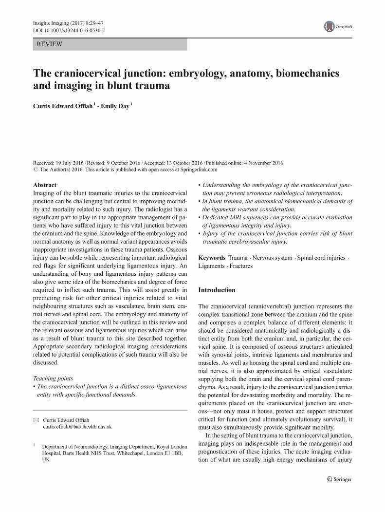
Embryology
In relation to the biomechanics of the craniocervicaljunction and the impact of trauma on this structure, itis useful to visualise the craniocervical junction as com-posed of two components: the first is a central pillarconsisting of the central basiocciput (even though it isanatomically part of the skull base), odontoid process(dens or peg) and the C2 vertebral body; the secondcomponent consists of the two-ringed structures sur-rounding the central pillar—these are the ring of theforamen magnum including the lateral portions of thebasiocciput, the exocciput incorporating the occipitalcondyles and the opisthion (the posterior margin of theforamen magnum), and the ring of the C1 vertebra(atlas) consisting of the anterior and posterior archesand la te ra l masses of the a t las [2–8] (Fig . 1 ) .Functionally, the latter stacked two-ringed componentallows limited rotation around the central pillar as wellas intrinsic limited flexion-extension. Ligaments bindthese two structural components of the craniocervicaljunction providing stability. Knowledge of the embryol-ogy of the craniocervical junction is germane to thisanalogy of a two-component structure and also helpsto confidently distinguish developmental anomalous/normal variant appearances of the imaged osseouscraniocervical junction from genuine traumatic injury.While detailed description of the embryological devel-opment of the craniocervical junction is beyond thescope of this review, a brief summary of selected as-pects will be given.
The craniocervical junction is of mesodermal originwhich appears in the 3rd gestational week. During gas-trulation, cells from the embryonic plate condense toform the parachordal mesoderm on each side of the no-tochord. This mesoderm eventually separates into seg-mental clusters called somites. These paired somites(the number of which is species-specific—42 pairs inhumans) will eventually give rise to the smooth muscleof the dermis, axial skeletal musculature and the verte-bral column (amongst other structures). Once mature,somites differentiate into ventromedial sclerotomes and
dorsolateral dermomyotomes. The sclerotomes eventu-ally develop into vertebral bodies, neural arches, liga-ments and membranes [2–8].
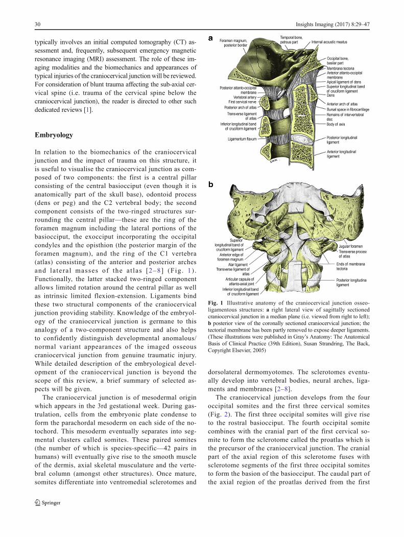
The craniocervical junction develops from the fouroccipital somites and the first three cervical somites(Fig. 2). The first three occipital somites will give riseto the rostral basiocciput. The fourth occipital somitecombines with the cranial part of the first cervical so-mite to form the sclerotome called the proatlas which isthe precursor of the craniocervical junction. The cranialpart of the axial region of this sclerotome fuses withsclerotome segments of the first three occipital somitesto form the basion of the basiocciput. The caudal part ofthe axial region of the proatlas derived from the first
Fig. 1 Illustrative anatomy of the craniocervical junction osseo-ligamentous structures: a right lateral view of sagittally sectionedcraniocervical junction in a median plane (i.e. viewed from right to left);b posterior view of the coronally sectioned craniocervical junction; thetectorial membrane has been partly removed to expose deeper ligaments.(These illustrations were published in Gray’s Anatomy: The AnatomicalBasis of Clinical Practice (39th Edition), Susan Strandring, The Back,Copyright Elsevier, 2005)
30 Insights Imaging (2017) 8:29–47
cervical somite gives rise to the apical segment of thedens. The lateral region of the proatlas eventually givesrise to the occipital condyles and the remainder of theanterolateral foramen magnum [3, 4, 6] (Fig. 2).
The caudal half of somite five and the cranial half ofsomite six combine to form the first cervical sclerotome.Similarly, the caudal half of somite six and the cranialhalf of somite seven combine to form the second cervi-cal sclerotome. Part of the first cervical sclerotomegives rise to the basal part of the odontoid peg (dens)while part of the second cervical sclerotome gives riseto the body of the axis (C2 vertebra). A distinct featureof the first and second cervical sclerotomes compared tothe more caudal sclerotomes is the absence of the con-version of part of the sclerotomes to the annulusfibrosus and nucleus pulposus of the intervertebraldiscs. Instead, this tissue disappears and the mesen-chyme at these junctional sites turns into the upper den-tal synchondrosis between the apical dens and basaldens and the lower dental synchondrosis between thebasal dens and the body of the axis. Hence, the C2 ver-tebra is distinctive in that it is derived from three adja-cent sclerotomes which ultimately give rise to cranial aswell as vertebral elements and this vertebra is the trueembryological juncture of the cranium and the spine
and, therefore, must, somewhat challengingly, servethe biomechanical requirements of both [3, 6].
The atlas and the axis embryology
The lateral zone of the first cervical sclerotome develops intothe posterior arch of the C1 vertebra while the lateral zone ofthe second cervical sclerotome develops into the arch of theaxis (C2 vertebra; Fig. 2). The anterior arch of the C1 vertebradevelops from a small mesenchymal off-shoot ventral to boththe notochord and the axial segment of first cervicalsclerotome called the hypochordal bow. [The hypochordalbow of the proatlas gives rise to a small osseous midline tu-bercle attached to the ventral surface of the basiocciput belowthe anterior margin of the foramen magnum (basion) and fre-quently visible on CT (and MRI) of the mature normalcraniocervical junction].
Ligament embryology
The apical ligament is derived from the axial proatlas. The alarligaments and the transverse ligamentous component of thecruciform (cruciate) ligament develop from the axial compo-nent of the first cervical sclerotome.
Chondrification and ossification of C2 vertebraand radiology
The membranous C2 vertebra in the early part of the firsttrimester consists of three median segments: the apicaldental segment, the basal dental segment and the body ofthe axis. These three segments chondrify at 6 weeks ofgestation but remain segregated by the upper and lowerdental synchondroses [8–11]. Ossification occurs in threestages: the first ossification centre appears in the body ofthe the C2 vertebra at 4 months of gestation; the secondwave of ossification appears at 6 months of gestation astwo ossification centres, one on each side of the basaldental segment—these two centres integrate and fuse atbirth when they should have begun to show some attemptat osseous fusion but the non-ossified cartilage may stillbe evident radiologically into the 6th year of life (Fig. 3a–f); the third wave of ossification appears in the apical densat 3 to 5 years of age—ossification of the apical dens andfusion across the upper dental synchondrosis is not com-plete until adolescence (Fig. 3a–f) [8–11].
Anatomy and biomechanics
The craniocervical junction is composed of two major joints:the atlanto-occipital joint and the atlanto-axial joint (Figs. 1and 4). These two joints are responsible for the majority of the
OccSom1
OccSom2
OccSom3
CSom3
CSom2
CSom1
OccSom4Proatlas
BO, Bas
ApDensCScler1
CScler2BaDens
AxBody
} C2
OC, FMalo
Atparch} C1
HypochB
Ataarch
} C0
Fig. 2 Schematic of craniocervical junction developmental segmentationand resegmentation during embryogenesis. Abbreviations: OccSom1 -occipital somite 1; OccSom2 - occipital somite 2; OccSom3 - occipitalsomite 3; OccSom4 - occipital somite 4; CSom1 - cervical somite 1;CSom2 - cervical somite 2; CSom3 - cervical somite 3; CScler1 - cervicalsclerotome 1; CScler2 - cervical sclerotome 2; BO - basiocciput; Bas -basion; OC - occipital condyles; FMalp - anterolateral foramen magnumand opisthion; Ataarch - anterior arch of C1 vertebra (atlas); Atparch -posterior arch of C1 vertebra (atlas); ApDens - apical segment of the dens;BaDens - basal segment of the dens; body of C2 vertebra (axis). Severedblack line denotes the embryological separation between the cranial skullbase and cervical spine during craniocervical junction development
Insights Imaging (2017) 8:29–47 31

movement available in the entire cervical spine and the ana-tomical structure of each is based on different biomechanicalprinciples. The mechanical properties of the atlanto-occipitaljoint are primarily determined by bony structures, whereasthose of the atlanto-axial joint are primarily determined byligamentous structures.
The occipital bone and the atlanto-occipital (C0-C1) joints
The occipital bone encompasses the foramen magnum and ex-tends from the clivus anteriorly to the lambdoid suture posterior-ly. The occipital condyles angle medially and inferiorly from theposterior to anterior: this angulation limits the mobility of theatlanto-occipital joints (i.e. C0-C1 joints), particularly in axialrotation compared with the atlanto-axial joint (i.e. C1-C2 joint)[12–14]. The predominant movements at the atlanto-occipitaljoint are flexion and extension. Lateral flexion at the atlanto-occipital joint is significantly limited by the contralateral alarligament.
The atlanto-axial (C1-C2) joints
The atlanto-axial joints (i.e. C1-C2 joints) allowmobility in flex-ion, extension, axial rotation and, to a lesser degree, lateral flex-ion as a result of the biconvex and inherently unstable constructof the joint; it is the ligaments (transverse ligament and alarligaments) related to this particular articulation which stabilisethe joint complex. In the event of traumatic disruption of theseligaments, the atlanto-axial joints are poorly equipped to tolerateaxial rotation. This is in stark contrast to the atlanto-occipitaljoints which are less affected by ligamentous injury [15, 16].
Fig. 4 Coronal three-dimensional T2 SPACE (sampling perfection withapplication-optimised contrasts using different flip-angle evolutions) se-quence image through normal craniocervical junction [Siemens 1.5 TeslaMRI scanner: slice thickness: 0.8 mm (no interslice gap), TR (time torepetition): 1500 ms, TE (time to echo): 129 ms, FOV (field of view):160 mm, number of excitations (NEX) averages: 1.6, matrix: 261 × 256,acquisition time: 6.5 ]in) demonstrating normal MRI appearances of thetransverse ligament (thick arrows) and alar ligaments (thin arrows)
Fig. 3 Progressive ossification of C2 vertebra: a: sagittal reconstructedCT image of the craniocervical junction of a 6-year-old male who fell 30feet off a balcony—ossification has not yet begun in the chondrifiedapical dens (black arrow) in this 6-year old and the lower dentalsynchondrosis (white arrow) is also evident as non-ossified cartilage.C2-C3 pseudosubluxation is present.; b: volume-rendered three-dimen-sional reconstructed CT image of the C2 vertebra of the same 6-year-oldmale—the apical dens is non-ossified (arrow) and the ossified basaldental segment (outlined asterisk) and the body of the C2 vertebra (blackasterisk) have not yet fused; c: sagittal reconstructed CT image of thecraniocervical junction of a 5-year-old male who fell from a first floorwindow—ossification has begun but is incomplete in the chondrifiedapical dental segment (white arrow) and a thin ossifying lower dentalsynchondrosis (black arrow) is evident. The appearances should not bemisinterpreted as fracture changes despite the high-energy clinical in-formation apparent. C2-C3 pseudosubluxation is again present; d:volume-rendered three-dimensional reconstructed CT image of the C2vertebra of the same 5-year-old male—the ossification of the apical densis evolving (white arrow) and the lower dental synchondrosis is stillvisible (thin black arrow); f: sagittal reconstructed CT image of thecraniocervical junction of a 6-year-old female who was a pedestrianstruck by a car travelling at moderate speed—advanced ossification ofthe apical dental segment is present (black arrow) with early ossificationacross the upper synchondrosis (white arrow). Pseudosubluxation at theC2-C3 level is present; f: volume-rendered three-dimensional recon-structed CT image of the C2 vertebra of the same 6-year-old female—ossification across the upper synchondrosis (thin white arrow) and low-er synchondrosis exhibits progressive features as union of the ossifica-tion centres proceeds
32 Insights Imaging (2017) 8:29–47

Craniocervical ligaments
Alar ligaments
These paired ligaments attach the axis to the base of the skull(Figs. 1 and 4) and originate from the posterior surface of theupper third of the dens and typically travel caudocranially (in50 % of cadeveric dissections) or horizontally (in 50 % ofsubjects); the exact insertion point of the alar ligaments hasbeen subject to some contention with researchers variablydescribing insertion on the medial aspect of the occipital con-dyles or the anterolateral aspect of the foramen magnum [14,17–21]. Each ligament is narrowest at its origin and compar-atively wider at its insertion giving it a BV-shaped^ configu-ration [20]. The alar ligaments limit axial rotation and lateralflexion on the contralateral side and, apart from the transverseligament, are the strongest stabilisers of the atlas preventinganterior displacement in the event of rupture of the transverseligament. Together with the transverse ligament (transverseatlantal ligament; see below), the alar ligaments are primarystabilisers of the craniocervical junction.
Cruciform ligament (cruciate ligament)
The cruciform ligament is composed of transverse and verticalparts which form a cross behind the odontoid peg (Figs. 1 and4) [14, 16, 19]. The vertical component which is relativelyweak and offers no discernible craniocervical stability consistsof a cranially orientated longitudinal band which inserts on tothe upper surface of the clivus between the apical ligament andtectorial membrane and a caudally directed band which insertson to the posterior surface of the body of the axis.
Transverse ligament
The transverse ligament (sometimes termed the transverseatlantal ligament) of the cruciform ligament complex is argu-ably the most important ligament in the body. It is the largest,thickest and, crucially, the strongest of the craniocervical junc-tion ligaments (and, in fact, the strongest ligament in the entirespine) and, therefore, a primary stabiliser of the craniocervicaljunction. It arches behind the odontoid peg attaching to atubercle arising from the medial aspect of each lateral massof the atlas (Figs. 1 and 4). The transverse ligament is centralto stability of the craniocervical junction, fixing the odontoidpeg firmly to the posterior aspect of the anterior arch of theatlas. A synovial capsule is situated between the odontoidprocess and the transverse ligament. The tectorial membrane,epidural fat and dura are located posterior to the transverseligament. The transverse ligament serves as the major stabilis-er of the atlanto-axial articulation: it permits rotation at the
atlanto-axial joints while, at the same time, the alar ligamentswill prevent excessive rotation. Tears of the transverse liga-ment typically occur laterally at the attachment to the tubercleon the atlas.
Tectorial membrane
This thin structure represents an upward extension of the pos-terior longitudinal ligament (Fig. 1). It forms the posteriorborder to the supraodontoid space or apical Bcave^ [14, 22]and runs posterior to the cruciform ligament. It extends crani-ally to the clivus (as far cranially as the spheno-occipitalsynchondrosis) and caudally to the posterior surface of thebody of the axis. It attaches as far laterally as the hypoglossalcanals and, at the level of C0-C1, merges with the atlanto-occipital capsular ligaments (Arnold’s ligaments). The cranialportion of the membrane is adherent to and anatomically in-distinguishable from dura [14, 23].
Capsular ligaments
The capsular ligaments of the atlanto-occipital and atlanto-axial joints (which are paired synovial joints) are typicallydescribed as thin and loose.
Apical ligament
This ligament extends from the tip of the odontoid process tothe basion and is situated between the anterior atlanto-occipital membrane and the cruciform ligament (Fig. 1); it issurrounded by fat, connective tissue and a venous plexuswhich accounts for the slightly variable signal characteristicsof this supraodontoid space or Bapical cave^ on MR imaging.It may be absent in up to 20 % of subjects based on cadavericdissections undertaken by Tubbs et al. [14, 19, 22, 24].Despite it being renowned, this ligament probably offers little,if any, significant contribution to craniocervical junctionstability.
Anterior atlanto-occipital membrane
This thin structure attaches the anterior aspect of the atlas tothe anterior rim of the foramen magnum (Fig. 1) and is locatedimmediately posterior to the prevertebral muscles [14, 19, 25].It forms the anterior wall of the supraodontoid space (which isvery discernible on MRI assessment owing to its contents offat and veins) which also houses the alar and apical (andBarkow) ligaments. It serves to limit atlanto-occipital exten-sion at the craniocervical junction.
Insights Imaging (2017) 8:29–47 33
Posterior atlanto-ocipital membrane
Although believed to play very little part in stability of theatlantooccipital articulation, the posterior atlanto-occipitalmembrane is important because it is highly visible on MRIassessment and also exhibits some specific anatomical featureswhich may be misinterpreted on imaging as traumatic disrup-tion. This broad ligament attaches the posterior arch of the atlasto the posterior margin of the foramen magnum and is contin-uous with the posterior atlantoaxial membrane and, subse-quently, the ligamentum flavum [14, 19, 25] (Fig. 1).Laterally, it may extend over the capsules of the atlanto-occipital joints. Posteriorly, it is related to the rectus capitisposterior minor muscle and, anteriorly, to the dura mater.Interdigitations with both the dura mater and the related rectuscapitis posterior minor muscle parenchyma may be present inthis ligament; additionally, a connective tissue bridge(exhibiting increased vascularity) joining the rectus capitis pos-terior minor muscle to the spinal dura is frequently present,particularly in the midline [14, 26–28]. This myoligamentouscomplex (comprising the posterior atlanto-occipital membrane,interspinous ligament, ligamentum nuchae, rectus posterior ma-jor and minor muscles and obliquus capitis supripr and inferiormuscles) adds further stability to the craniocervical junction[29]. An important consideration in trauma of this componentof the craniocervical junction is the vertebral artery whichpierces the posterior atlanto-occipital membrane and then thedura mater before entering the posterior fossa.
Nuchal ligament (ligamentum nuchae)
This is a cephalic extension of the supraspinous liga-ment and extends from the spinous process of the C7
vertebra attaching to the inion of the occipital bone. Asturdy structure, it limits hyperflexion of the cervicalspine [14].
There are a number of other anatomically defined smallBaccessory^ ligaments related to the craniocervical junc-tion in addition to the more substantial ligaments outlinedabove (Table 1). While demonstrable on cadaveric dissec-tion, both the identification of these smaller ligaments (orneed to identify these ligaments) on clinical MRI assess-ment as well as the contribution of these structures tooverall craniocervical junction stability is limited and, assuch, injury to these ligaments in isolation is probably oflow clinical significance. However, individual ligamen-tous injury at the craniocervical junction infrequently oc-curs in isolation and, therefore, as an example, MRI evi-dence of injury to the apical ligament, which is an incon-sistent ligament on normal cadaveric dissection and con-tributes little to craniocervical stability, is still a valuableMRI finding when present as it indicates the likelihood ofother coexist ing more clinical ly relevant osseo-ligamentous injuries which should then be sought on theMRI sequences available.
Normal variant mimicking fracture
There are a number of developmental anomalies of thecraniocervical junction which, while uncommon, canmimic fractures of the craniocervical junction butshould not be misinterpreted as such as this can havesignificant ramifications on the management of patientspresenting for imaging with a question of craniocervicalinjury.
Table 1 Anatomicallydiscernible ligaments related tothe craniocervical junction andMRI discernibility as discreteligamentous structures, andrelative contribution to stability ofthe craniocervical junction (inisolation)
Anatomical ligaments of the craniocervical junction MRI-discernible Stability contribution
Tectorial membrane + ++
Alar ligament + ++
Cruciform (cruciate) ligament - transverse + ++
Cruciform (cruciate) ligament - longitudinal +/− +/−Apical ligament +/− +/−Barkow ligament +/− +
Atlanto-occipital capsular ligament + +
Atlanto-axial capsular ligament + +
Anterior atlanto-occipital membrane + +
Posterior atlanto-occipital membrane + +
Anterior atlanto-axial membrane + +
Nuchal ligament (ligamentum nuchae) + +
Lateral atlanto-occipital ligament − −Accessory atlanto-axial ligament − −Transverse occipital ligament − −
34 Insights Imaging (2017) 8:29–47

Condylus tertius
When the hypochordal bow of the fourth occipital sclerotome(proatlas) fails to integrate, an ossified remnant may be evi-dent at the caudal end of the basi-occipit called the condylustertius or the third occipital condyle (Fig. 5a and b). It isusually single but may be multiple and may form an arthrosisor pseudoarthrosis with the odontoid process or the anteriorarch of the atlas. Awell-corticated margin and a site typical ofthe embryological location of the hypochordal bow as well asthe occasional association with an os odontoideum (see be-low) will aid radiological distinction from fracture [30].
Posterior rachischisis
Absence of the posterior arch of the atlas is rare and usuallyisolated but can be associated with bilateral atlanto-axial sub-luxation or Boffset^, mimicking Jefferson’s fracture [30].Developmental clefts of the arch of the atlas are more com-mon. Such rachischisis is more common posteriorly [30, 31];the vast majority are midline (97 %; Fig. 6). Less commonly, a(postero)lateral rachischisis may be observed through the
region of the sulcus of the vertebral artery (3 %); this maybe unilateral (Fig. 7) or bilateral (Fig. 8).
Anterior rachischisis/split atlas
Anterior arch rachischisis is rare (occurring in less than 0.1 %of autopsy dissections) and is typically associated with a pos-terior arch rachischisis in which case it may be termed a Bsplitatlas^ (Fig. 9) [30–32].
Ossiculum terminale
The persistent ossiculum terminale results from failure of fusionof the secondary ossification centre (Bterminal ossicle^) to theremainder of the odontoid process which has usually occurred
Fig. 5 Condylus tertius: a sagittal reformatted CT image through thecraniocervical junction of a 54-year-old male cyclist who fell of his bicy-cle at speed sustaining facial fractures. The condylus tertius of unfusedhypochordal bow is demonstrated (thick arrow) and is an important mim-ic of fracture at the basion. Note the depressed comminuted facial frac-tures involving the frontal sinus and nasal bone (thin arrows); b axial CTimage of the same patient demonstrates the unfused bone remnant at theleft side of the basion (arrow), not to be mistaken for a displaced fracturefragment
Fig. 6 Posterior rachischisis: axial CT image through the atlas (C1vertebra) of the craniocervical junction of a road traffic accident victim(pedestrian versus car with Bbullseye^ impact of the victim’s head againstthe windscreen of the car) demonstrating a developmental posteriorrachischisis (arrow) which should not be confused with an acutefracture. The well-corticated margin of the cleft should alert one to thedevelopmental nature of the anomaly in addition to the typical locationand unity of the defect compared to a traumatic aetiology
Fig. 7 Unilateral posterolateral rachischisis: axial CT image through theatlas (C1 vertebra) of the craniocervical junction of an 8-year-old femalechild involved in a road traffic accident (pedestrian versus car) whosustained head injuries with seizures. A developmental unilateral rightposterolateral rachischisis is present (arrow). There were nocraniocervical junction or sub-axial cervical spine fractures present
Insights Imaging (2017) 8:29–47 35

by 12 years of age. It may be confused with a (type I) odontoidfracture. Identification of a smooth corticated margin is, again,central to discriminating the two aetiologies [5–11, 30, 32].
Os odontoideum
First described in 1886 by Giacomini and derived from theLatin osmeaning bone and odontoideummeaning tooth-form,this represents a separate ossicle with a smooth cortical borderlying superior to a small hypoplastic dens and body of the axisin the location of the odontoid process (Fig. 10) and maysimulate a (type II) odontoid fracture [5–11, 30, 32]. It stillremains contentious if the os odontoideum represents a post-traumatic acquired anomaly or a truly congenital anomaly.
The anterior arch of the atlas may be rounded and hypertro-phic in contrast to the normal anterior archmorphology.Whilethe (type II) odontoid fracture is typically associated with aflattened uncorticated sharp margin to the adjacent body of theaxis and normal morphology to the anterior arch of the atlas,the os odontoideum exhibits a well-corticated convex uppermargin and rounded hypertrophic anterior atlas arch (Fig. 10).
Calcification in the alar ligament
Rarely, nodular calcification/ossification can be seen in thealar ligament which can mimic type III fracture of the occipitalcondyle or type I fracture of the odontoid process (see below).While rare, this can occasionally present as a imaging diag-nostic dilemma in the unconscious or intubated and ventilatedpolytrauma patient with high-risk injuries for craniocervicaltrauma. The calcification usually presents as nodular relativelywell-circumscribed calcification/ossification in the region ofthe alar ligament on CT imaging (Fig. 11) [33].
Craniocervical junction blunt traumatic injury
Basiocciput fractures
These fractures account for only 2 % of cranial fractures but theassociated mortality is high, estimated at between 24% to 80%because of the proximity to the brainstem and the high inci-dence of neurological injury (particularly cranial nerve VI) andvascular injury [34]. The characteristic patterns described are
Fig. 10 Os odontoideum: sagittal reformatted CT image of thecraniocervical junction performed as part of a trauma CT assessment ofa young female victim of a fall from height demonstrates a pre-existing osodontoideum (large white arrow) mimicking a type II odontoid processfracture. While the (type II) odontoid fracture is typically associated witha flattened uncorticated sharp margin to the adjacent body of the axis anda normal morphology to the anterior arch of the atlas, the os odontoideumexhibits a well-corticated convex upper margin. A commonly associatedrounded hypertrophic anterior atlas arch is also present (small whitearrow). This, together with an associated condylus tertius (small blackarrow) which represents a remnant hypochordal bow, further confirms thenon-acute traumatic aetiology of the odontoid process appearances
Fig. 9 Split atlas: axial CT image through the atlas (C1 vertebra) of thecraniocervical junction of a 9-year-old female struck by a car and sustain-ing severe chest injuries. The victim was intubated at the roadside. Adevelopmental Bsplit atlas^ is present with anterior and posteriorrachischisis defects present (arrows)—this is an important but rare mimicof fracture of the C1 vertebra. There were no acute fractures of thecraniocervical junction in this patient
Fig. 8 Bilateral posterolateral rachischisis: axial CT image through theatlas (C1 vertebra) of the craniocervical junction of a 47-year-old femalewho suffered blunt trauma to the head and complained of neck pain.Bilateral developmental posterolateral rachischisis is evident (arrows).There was no acute fracture of the craniocervical junction present
36 Insights Imaging (2017) 8:29–47

transverse, oblique and longitudinal. The transverse andoblique patterns typically result from lateral blunt force impactor crush injuries, and associated cranial nerve injury and inter-nal carotid injury has been described. The longitudinal fracturesresult typically from an axial loading mechanism through thevertex and may be associated with vertebrobasilar vascular in-jury and brainstem infarction.
Basiocciput fractures may be seen in conjunction withcraniocervical injury including the rare entity of the retroclivalepidural haematoma (Fig. 12a–d). The retroclival epiduralhaematoma seems to be more common in the paediatric popula-tion; the reduced stability of the paediatric craniocervical junctionbecause of smaller occipital condyles and a more horizontallyorientated atlanto-occipital articulation presumably predisposesthe infant craniocervical junction to this injury. The relativelyreduced adherence and strength of the paediatric tectorial mem-brane may allow traumatic detachment and disruption of localvascular structures such as the basilar venous plexus, the dorsalmeningeal branch of the meningohypophyseal trunk and a men-ingeal branch of the ascending pharyngeal artery (which anasto-moseswith themeningohypohyseal trunk, inferolateral trunk andarterial arcades related to the odontoid process) leading to bloodaccumulation in the retroclival area. Regardless, in the adult andpaediatric populations, the retroclival epidural haematoma indi-cates traumatic injury of the sturdy tectorial membrane and sug-gests a traction/distraction injury mechanism [18, 34].
Occipital condyle fractures
Until the emergence of CT technology, occipital condyle frac-tures were considered rare but, in fact, were probably signifi-cantly under-reported. The first report of an occipital condylefracture may date back to 1817 when Sir Charles Bell
described the case of a patient who was well until the timeof discharge when he reached down to pick up his belongingsand died suddenly—an occipital condyle fracture was identi-fied at post-mortem and was presumed to have compressedthe medulla [35, 36]. The reported incidence of occipital con-dyle fractures ranges from 4 % to 19 % [35, 37–40].
On the medial aspect of the occipital condyle, there is a tuber-cle for attachment of the alar ligament. The hypoglossal canal isan important anatomical relation located above the middle thirdof the occipital condyle and transmits the hypoglossal nerve (cra-nial nerve XII), a meningeal branch of the ascending pharyngealartery and an emissary vein. An important lateral relation to theoccipital condyle is the jugular foramen which transmits cranial
Fig. 12 Retroclival epidural haematoma in a 12-year-old female whowas a pedestrian struck by a car travelling at high speed: a axial non-contrast CT brain image through the posterior fossa demonstrateshyperdense retroclival abnormality (white arrow) in keeping with epidu-ral haematoma; b: coronal reformatted CT image of the craniocervicaljunction of the same patient demonstrates a left basiocciput fracture ex-tending to the left occipital condyle (type II occipital condyle fracturepattern; black arrows). There is asymmetrical widening of the right lateralatlanto-dental space raising the likelihood of right alar ligament disrup-tion; c: sagittal T2-weighted image of the same patient through thecraniocervical junction demonstrates the retroclival epidural haematoma(short white arrows) associated with traumatic signal change oedema andhaemorrhagic fluid tracking between the deep and superficial layers of theanterior atlanto-occipital membrane (thin long white arrow) and aroundthe membrane over the superior aspect of the anterior arch of the C1vertebra (atlas; black arrow); d: axial T2-weighted image through thecraniocervical junction at the level of the occipital condyles of the samepatient with magnified inset demonstrating an intact left alar ligament(white arrow) but loss of integrity of the right alar ligament in the com-parative contralateral location as a result of rupture. A traumaticoedematous contusion signal abnormality is present in the right and cen-tral cervico-medullary parenchyma (black arrow)
Fig. 11 Calcification of the alar ligament: coronal reformatted CT imageof the craniocervical junction performed as part of a trauma CTassessment of a 59-year-old male driver involved in motor vehicle colli-sion complaining of neck pain on presentation to hospital. The well-circumscribed nature of this nodular area of calcification/ossification inthe left alar ligament helps to discriminate this lesion from a fracture
Insights Imaging (2017) 8:29–47 37

nerves IX–XI, the internal jugular vein, the inferior petrosal sinusand the posterior meningeal artery [41–44].
Clinical presentation of occipital condyle fractures is variablebut concomitant head injury is a frequent finding. The anatomicallocation of the occipital condyles means that the brainstem, thelower cranial nerves (cranial nerves IX–XII) and venous andarterial vessels are at particular risk in the event of fracture.Lower cranial nerve palsies (including Collet–Sicard syndromewhere all of the cranial nerves IX–XII are affected) may be acutein two-thirds of cases [35, 41, 45–51]. Delayed cranial nervepalsies may result from migration of fracture fragments or pro-liferation of fibrous tissue. Vascular complications related to oc-cipital condyle fractures include internal carotid artery and verte-bral artery traumatic dissection, arteriovenous fistulae of the pos-terior inferior cerebellar artery andWallenberg syndrome (lateralmedullary syndrome) [35, 49].
CT assessment is mandatory to establish or confirm the diag-nosis. MRI allows evaluation of the associated ligaments and, inparticular, integrity of the alar ligament, transverse ligament andthe tectorial membrane; it also allows evaluation of the relation-ship of the fractured segment on surrounding structures, particu-larly the brainstem and neurovascular structures.
The most widely accepted classification system of occipitalcondyle fractures was described by Anderson and Montesanoand incorporates the probable mechanism of injury and thepotential risk of resultant instability [52]. This system de-scribes three types of occipital condyle fractures. Type I isan impaction type fracture resulting in comminution of theoccipital condyle with or without minimal fragment displace-ment and the mechanism is believed to be axial loading sim-ilar to Jefferson’s fracture; this fracture type is consideredstable because the tectorial membrane and contralateral alarligament are intact (Fig. 13). However, bilateral lesions mayclearly be unstable. Type II fracture (Fig. 14) is part of a more
extensive basioccipital fracture involving one or both occipitalcondyles and is associated with intact tectorial membrane andalar ligaments, preserving stability. The type III fracture(Fig. 15) is an avulsion fracture resulting in medial fragmentdisplacement into the foramen magnum; in this fracture type,the contralateral alar ligament and tectorial membrane mayhave been stressed resulting in partial tear or complete disrup-tion and it is thus considered potentially unstable.
Atlanto-occipital (occipito-atlantal) dislocation
This injury is associated with both high mortality and signifi-cant neurological morbidity: the force required to cause atlanto-occipital dislocation is such that the injury often proves fataland, therefore, antemortem imaging of this traumatic injury isuncommon [53–58]. Under normal anatomical conditions, theconvex occipital condyles sit within the concavity of the lateralmasses of the atlas. The joint is surrounded by a loose capsule.In the paediatric population, the articulating surface of the atlasat this joint is less concave, probably contributing to the greaterincidence of atlanto-occipital dislocation in this group [57, 58].The most important ligaments for stability of the atlanto-occipital articulation are the cruciform and alar ligaments andthe tectorial membrane. These ligaments are underdeveloped inthe paediatric population, further contributing to the incidenceof this injury in this patient group.
The Traynelis classification is largely descriptive and di-vides atlanto-occipital dislocation into three types which aredetermined by the direction of dislocation of the occipital con-dyles: type I injuries represent anterior displacement of theoccipital condyles in relation to the atlas (Fig. 16); type II inju-ries are distraction injuries with vertical displacement of theoccipital condyles in relation to the atlas (Fig. 17a and b); typeIII injuries describe posterior displacement of the occipital
Fig. 14 Type II occipital condyle fracture: coronal reformatted CT imageof the craniocervical junction performed as part of a CT traumogram in ayoung male pedestrian struck by a bus. The fracture of the left occipitalcondyle is associated with extension into the right basiocciput (blackarrows). Note the associated soft tissue emphysema and pneumorachiswithin the anterior epidural space of the cervical spine (white arrows)
Fig. 13 Type I occipital condyle fracture: coronal reformatted CT imagethrough the craniocervical junction performed as part of a CT traumaassessment in a middle-aged male driver in a high-speed motor vehiclecollision. A comminuted right occipital condyle fracture is present(arrow). The victim also sustained severe chest trauma and succumbedto his traumatic injuries the same day
38 Insights Imaging (2017) 8:29–47

condyles relative to the atlas [58–60]. Both the basion-densinterval (which is abnormal if greater than 10 mm in the adult
and greater than 12 mm in the paediatric patient) and thecondyle-atlas interval (which is abnormal if greater than2 mm in the adult and greater than 5 mm in the paediatricpatient) can be used to identify abnormality at the atlanto-occipital articulation; additionally, anterior displacement ofthe posterior margin of the odontoid peg and body of the axisrelative to the basion greater than 12 mm or posterior displace-ment of the posterior margin of the same relative to the basiongreater than 4 mm represents an abnormal relationship [58–60].
Fractures of the C1 vertebra (atlas)
Estimated to account for 25 % of craniocervical injuries, themost common causes are motor vehicle accidents and falls [29,
Fig. 16 Anterior atlanto-occipital dislocation (type I dislocation): sagittal(right) reformatted CT image of craniocervical junction of a post-mortemCT study of a victim of young male patient who sustained high–forceimpact to the cranium as a result of an industrial accident with resultantbilateral atlanto-occipital dislocation (right joint dislocation indicated byarrow). The victim died at the scene: such craniocervical trauma carries avery high mortality and, as a result, ante-mortem imaging of such injuriesis uncommon
Fig. 15 Type III occipital condyle fracture: a axial CT image through theatlanto-occipital level performed as part of a polytrauma CT assessmentof a young female pedestrian struck by a motorcyclist travelling at speed;b coronal CT image of the same patient. The type III occipital condylefracture can be subtle on CT imaging [indicated here on the right (arrow)]but may indicate a high-energy traumatic mechanism to the craniocervicaljunction with potentially unstable craniocervical spine injury related toalar ligament avulsion
Fig. 17 Jefferson’s fracture in a young male victim of a motor vehicleaccident who suffered cardiac arrest at the scene and succumbed to hisinjuries shortly after presenting to the trauma centre: a sagittal reformattedCT image of the craniocervical imaging assessment demonstrates severecraniocervical junction disruption with Jefferson’s fracture (type V) of theatlas (black arrow) and associated abnormally widened predental(atlantodental); white arrow) in keeping with transverse ligament disrup-tion and a pathologically widened basion-dens interval (black asterisk) inkeeping with a distraction mechanism likely disrupting the critical alarligaments, cruciform ligament (vertical band) and probably the tectorialmembrane to some degree as well as the C1-C2 components of theligamentum nuchae and flavum (white asterisk); b coronal reformattedCT image of the same patient confirms type II atlanto-occipital distraction(black arrow) associated with Jefferson’s fracture and disruption of theatlantoaxial joint on the left (large white arrow); the left atlantodentalinterval is abnormally widened (small white arrow) associated withJefferson’s fracture of the atlas
Insights Imaging (2017) 8:29–47 39

61–65]. Atlas fractures can occur in isolation but are frequentlyassociated with fractures of the axis and the subaxial cervicalspine and may also be associated with rupture of the transverseligament and closed head injury [29, 61–64]. Complicationsrelated to vertebral artery dissection injury and lower cranialnerve palsies (IX–XII) have been reported [66]. Cervico-medullary parenchymal injury occurs more frequently whenfractures of the atlas coexist with axis or subaxial cervical spineinjury and are typically associated with transverse ligamentdisruption [61, 62, 64, 67] (Fig. 18a–c).
Jefferson’s fractures
Initially described by Sir Geoffrey Jefferson, atlas fracturescan be classified as type I which are fractures involving theposterior arch alone, type II fractures which involve the ante-rior arch alone, type III (the classical Jefferson fracture) whichare bilateral posterior arch fractures associated with a unilat-eral or bilateral anterior arch fracture, type IV which involvethe lateral mass and type V (Fig. 17a and b) which are trans-verse fractures of the anterior arch [29, 68, 69]. A crucialstabiliser of the atlanto-axial articulation is the transverse lig-ament and the integrity of this ligament determines the stabil-ity or instability of atlas fractures.
Post-mortem studies have revealed more detail of the bio-mechanics of such fractures [70, 71]: atlas fractures occurprimarily from an axial loading mechanism; when the axialloading occurs through the occiput, distraction of the lateralmasses of the atlas occurs resulting in increased radial stresson the ring of this vertebra which subsequently Bfails^ orfractures at the weakest points which are the junction pointsbetween the anterior and posterior arches with the lateralmasses (i.e. four in total); transverse ligament injury is com-mon with atlas fractures but, crucially, transverse ligamentinjuries can occur without bone injury (Fig. 21a–c). The re-maining key craniocervical ligaments are usually spared un-less there are associated fractures of the occipital condyles. Onplain radiographic and CT imaging, an atlanto-dental intervalof greater than 3 mm in an adult and greater than 5 mm in achild, particularly in the absence of any evidence of fracture,warrantsMRI assessment of the craniocervical junction as thisis highly suggestive of transverse ligament disruption.
A cautionary note is the radiographic normal variant ofBpseudospread^ of the atlas which generally occurs in childrenunder 7 years of age and in which the ossified lateral masses ofthe atlas are projected beyond the ossified articular surface ofthe axis (C2 vertebra) [72]. This may give the false impressionof a Jefferson’s fracture and has, hence, been termed Bpseudo-Jefferson’s^ by some authors. It is due predominantly to thedifferential faster growth rate of the atlas compared to the axisin infancy with the axis growth rate eventually catching up withthat of the atlas. CT evaluation will clarify this falsepositive radiographic impression confirming an intact atlas.
Fractures of the C2 vertebra (axis)
The incidence of neurological deficit and acute mortality as-sociated with fractures of the axis approach 8.5 % and 2.4 %,
Fig. 18 Transverse ligament and alar ligament rupture in a middle-agedmale driver of a car involved in a collision with a bus; the victim wasquadriparetic and respiratory-compromised at the scene: a axial image of3D T2 SPACEMRI sequence demonstrates marrow oedema and fractureof the left anterior arch of the atlas extending to and involving the medialtubercle attachment of the transverse ligament on this side associated withrupture and detachment of the the transverse ligament at this site (arrow).Cord oedema is evident (black arrow); b coronal image of the same MRIstudy demonstrates traumatic signal abnormality and tear of the left alarligament (thick black arrow) as well as the loss of integrity of the left sideof the transverse ligament (thick white arrow). Some intrasubstance high-signal strain injury is noted affecting the right alar ligament at its condylarattachment (thin black arrow). Traumatic effusions are present in theatlanto-occipital and atlanto-axial joints bilaterally but are more markedon the left indication associated with capsular ligament strain injury (thinwhite arrows); c sagittal image of the same MRI study demonstrateshaemorrhagic cord injury at the C1-C2 level (thin black arrow), abnormalhaemorrhagic signal and fullness in the supra-odontoid space (Bapicalcave^) related to the apical ligament (thick black arrow), an intact tecto-rial membrane but abnormal traumatic signal change in the anterioratlanto-occipital membrane (thin white arrow) associated with a largehaematoma in the prevertebral space (thick white arrow)
40 Insights Imaging (2017) 8:29–47

respectively [73–76]. In addition, the incidence of neurologi-cal deficit is significantly higher in combination atlas-axisfractures than when either of these fractures occurs in isolation[73, 77] (Fig. 18a–c).
Odontoid fractures
The classification of odontoid fractures developed byAnderson and D’Alonzo is still in use today dividing odontoidfractures into three types [78] and with the only relevant mod-ification introduced by Hadley et al. who defined a subclass ofthe type II fracture [79]. Type I is a fracture through the upperpart of the odontoid process; type II is a fracture at the junctionof the odontoid process with the body of the axis and is themost common type; type III is a fracture that extends down-wards into the cancellous portion of the body of the axis and isthe next most common pattern (Fig. 19). The type IIa subclasshas additional chip fragments at the anterior or posterior as-pect at the base of the dens and uniformly leads to non-unionand, therefore, may warrant more pressing consideration forearly surgical stabilisation and fusion [79].
The type II fracture is more prone to non-union and, there-fore, such fracture types may need to proceed to surgical fu-sion as opposed to external/cervical collar immobilisation forhalo-vest immobilisation for management [77]. The reason forthis propensity to non-union seems to relate to the vascularanatomy of the axis: there are two vascular arcades that pro-vide blood supply to the axis, one supplying the body of theaxis and the other supplying the tip of the odontoid processwith a resultant zone of relatively poor blood supply at thebase of the odontoid process which may be rendered avascularafter fracture, particularly with displacement. An additionalcontributory factor may be that the odontoid process isenveloped by a synovium and, as a result, lacks a periostealblood supply. Traction by an intact apical ligament has also
been suggested to cause distraction at a type II fracture sitecompromising endosteal healing [73].
Odontoid process fracture in the elderly population issometimes considered a distinct entity warranting distinctmanagement considerations, particularly type II fractures inthe elderly. Lennarson et al. undertook a case–control studyproviding class II evidence in favour of surgery for patientsover 50 years of age demonstrating a 21-times higher rate ofnon-union when such fractures in this age range were treatedwith halo immobilisation [80]
Hangman’s fractures
Initially described in human subjects executed by hangingwith the knot of the noose positioned under the submentalregion, this fracture-type represents bilateral fractures of thepars interarticularis of the axis (Fig. 20a and b). While similarpatterns are evident in victims of motor vehicle accidents orsudden deceleration accidents and have led to common usageof the pseudonym, these traumatic spondylolistheses occur bya different biomechanical event in motor vehicle accidents orfalls, i.e., hyperextension and compression as opposed to
Fig. 19 Complex type III odontoid fracture of the atlas in a 32-year-oldmale driver involved in a high-speed motor vehicle collision. Coronalreformatted CT image of the craniocervical junction demonstrates frac-ture extension into the body of the C2 vertebra (black arrows) with afurther vertical fracture line extending through the right side of the body(white arrow)
Fig. 20 Classical hangman’s fracture in a 74-year-old male who felldown a flight of stairs: a axial CT image the C2 vertebra parsinterarticulares demonstrating the typical fracture line locations in thistype of classical hangman’s fracture (arrows); b sagittal reformatted CTimage through the right pars interarticularis demonstrates the typical frac-ture line location (arrows) which was also evident in the left parsinterarticularis (not shown)
Insights Imaging (2017) 8:29–47 41

hyperextension and distraction (in judicial hanging). The in-cidence of spinal cord and nerve root injury as a result ofhangman’s fracture is reportedly low. It is suggested that if apatient survives the initial injury, the relatively capacious ca-nal at the level of the axis affords some protection against cordinjury [73, 77, 81, 82]. The majority of these traumaticspondylolistheses can be treated with non-surgical methodssuch as halo immobilisation or cervical collar immobilisation.
Ligamentous injury in the absence of fracture
Ligamentous injury at the craniocervical junction may occurin both the paediatric and adult population following traumadespite the absence of fracture of the osseous structures of thecraniocervical junction (Figs. 21a–c and 22a–c). Such liga-mentous injury may be acutely symptomatic and may havelonger term sequelae if not identified acutely and managedappropriately, albeit frequently conservatively. There are po-tential medico-legal implications where failure has occurred toidentify and manage such injuries expeditiously.
Traumatic alar ligament injuries typically occur near thecondylar insertion. Alar ligament failure predisposes to exces-sive axial rotation with resultant compression of or dissectioninjury to the vertebral artery and damage to the spinal acces-sory nerves [14]. Damage to the alar ligaments is most typi-cally secondary to high-energy blunt trauma as might occur inmotor vehicle accidents. Contained alar ligament injury hasalso been implicated in the symptomatology related to whip-lash injury [21].
MRI evidence of injury of less clinically relevant ligamentssuch as the apical ligament or effusion in or around the supra-odontoid space (not to be confused with normal-variant incon-sistency of the apical ligament or venous plexus high signal inthe supra-odontoid space, respectively) should prompt asearch for strain injury, partial tear or full-thickness ruptureaffecting more clinically relevant stabilising ligaments of thecraniocervical junction (Table 1) in spite of absence of anyfracture abnormality on CT assessment.
Imaging modalities and techniques
CT is the initial imaging modality of choice in the setting ofacute traumatic injury of the craniocervical junction and cer-vical spine. An appropriately thin-section axial source data-setof 0.75 mm is recommended from which appropriate-resolution multi-planar reformats can be acquired (ideally,2 mm or less). Coronal and sagittal reformats are mandatory,particularly given the availability or multi-detector CT tech-nology and scrutiny of the axial source data-set as well asliberal use of angled/oblique reformats is also recommended.Imaging evaluation of soft tissue ligamentous injury at thecraniocervical junction requires appropriate MR imaging.Inclusion of an isovolumetric T2-weighted sequence allows
orthogonal post-processing assessment for enhanced radiolog-ical evaluation of the integrity of the key ligamentous struc-tures as well as the location of any telling traumatic peri-liga-mentous, intra-articular and periarticular effusions (Table 2).
Fig. 21 Craniocervical ligament injury in the absence of osseous injuryin a 28-year-old male who sustained unimpeded fall from 3 metres asso-ciated with head injury and neck pain. There was no fracture evident onCTassessment of the craniocervical junction and sub-axial cervical spine:a axial CT image through the C1-C2 level of the craniocervical junc-tion—there is widening of the left lateral atlanto-dental interval (blackarrow) despite the absence of any fractures, raising the likelihood ofcraniocervical ligamentous injury; b reconstructed axial T2-SPACE MRimage through the C1-C2 level of the same patient demonstrates disrup-tion of the left transverse (atlantal) ligament (thin long white arrows) andlocalised haemorrhagic effusion in the widened left lateral atlanto-dentalspace; c coronal T2-SPACE MR image through the craniocervical junc-tion of the same patient—the abnormal signal change related to thedisrupted left transverse (atlantal) ligament and surrounding effusion isdemonstrated (thick white arrow). The left alar ligament is mildly butabnormally stretched (thin white arrow). Small atlanto-axial andatlanto-occipital joint effusions are present (not annotated)
42 Insights Imaging (2017) 8:29–47

Traumatic rotatory atlanto-axial subluxation
Atlanto-axial rotatory subluxation (AARS) is relatively rare inthe adult population, occurring more commonly in the paediat-ric population. In adults, the most common cause is trauma. Ifthe facets become locked, then the term atlanto-axial rotatoryfixation (AARF) is often applied as the deformity is irreducible.Some two-thirds of the normal rotation that occurs in the cer-vical spine is derived from the atlanto-axial articulation.However, there is a biomechanical trade-off for this degree ofmobility which is stability. It is also important to bear in mindthat when the head is rotated normally, the neighbouring
segments of the vertebral arteries are structurally affected: theipsilateral vertebral artery will be kinked and the contralateralvertebral artery will be stretched. Hence, vertebral artery injuryor insufficiency is a potential complication associated withAARS. Clinically, patients may demonstrate torticollis andadopt the cock-robin position of the head (because of the ap-parent descriptive resemblance of a robin listening for a wormin the ground) and occipital pain may occur as a result of com-pression of the greater occipital nerve or the C2 nerve root.Patients may also experience vertigo, nausea, tinnitus and visu-al disturbances, possibly related to haemodynamic compromiseo f t h e ve r t eb r a l a r t e r y. Spa smod i c t o r t i co l l i s(sternocleidomastoid muscle spasm) should be distinguishedclinically from AARS—in the former, the shortenedsternocleidomastoid on the side contralateral to the directionof head rotation is creating the force producing the deformity,whereas in the latter, the lengthened sternocleidomastoid mus-cle on the side ipsilateral to the direction of head rotation dem-onstrates spasm in an attempt to correct the deformity [83]. CT(with or without incorporation of a dynamic protocol in thesetting of trauma if fracture is or is not demonstrated on thestatic CT study) and MRI (to assess soft tissue injury includingligamentous injury) are recommended. Probably the mostwidely used classification of AARS/AARF is that created byFielding and Hawkins which classifies the deformity in to fourtypes: type I is rotatory subluxation/fixation without anteriordisplacement of the atlas (i.e. the atlanto-dental interval is lessthan 3 mm); type II is rotatory subluxation/fixation with ante-rior displacement of the atlas of 3–5 mm; type III is rotatorysubluxation/fixation with anterior displacement of the atlas
Fig. 22 Multi-focal craniocervical junction osseo-ligamentous trau-matic injury in a 51-year-old male driver of a vehicle which collidedwith awall at high speed: a: axial CT image through the atlanto-occipitallevel demonstrates type —III left occipital condyle fracture (blackarrow) and type I right occipital condyle fracture (white arrow); b:sagittal T2-weighted image through the craniocervical junction of thesame patient—there is oedematous strain injury affecting the apical lig-ament (bold white arrow) with haemorrhagic fullness of the surroundingsupra-odontoid space (apical cave; not annotated). There is strain injuryof the transverse ligament with peri-ligamentous fluid surrounding theligament (black arrow) as well as widening of the anterior atlanto-dentalspace (not annotated). There is partial tear of the basion attachment ofthe anterior atlanto-occipitalmembrane (thin white arrow) and traumaticdisruption of the anterior atlanto-axial membrane (severed white arrow).Sizeable prevertebral haematoma and traumatic posterior paraspinal softtissue oedema are also present (black asterisks); c: coronal image of T2-SPACE sequence through the craniocervical junction of the same patientdemonstrates traumatic signal abnormality and partial tear of the left alarligament (long white arrow) compared with the greater integrity of theright alar ligament (long black arrow), abnormal signal related to dis-ruption of the left transverse ligament (short thin white arrow) comparedto the integrity of the right side of the ligament (short thin black arrow).Traumatic effusions are evident affecting both the atlanto-axial jointcapsules (Arnold’s ligaments) and the atlanto-occipital joint capsulesbilaterally (severed white arrows). Bilateral traumatic otomastoid effu-sions are present (not annotated) related to lateral skull base fractures(not depicted)
R
Insights Imaging (2017) 8:29–47 43
greater than 5 mm; type IV is rotatory subluxation/fixation withposterior displacement [83].
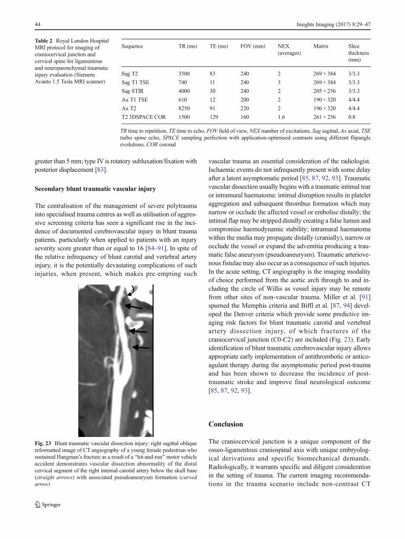
Secondary blunt traumatic vascular injury
The centralisation of the management of severe polytraumainto specialised trauma centres as well as utilisation of aggres-sive screening criteria has seen a significant rise in the inci-dence of documented cerebrovascular injury in blunt traumapatients, particularly when applied to patients with an injuryseverity score greater than or equal to 16 [84–91]. In spite ofthe relative infrequency of blunt carotid and vertebral arteryinjury, it is the potentially devastating complications of suchinjuries, when present, which makes pre-empting such
vascular trauma an essential consideration of the radiologist.Ischaemic events do not infrequently present with some delayafter a latent asymptomatic period [85, 87, 92, 93]. Traumaticvascular dissection usually begins with a traumatic intimal tearor intramural haematoma: intimal disruption results in plateletaggregation and subsequent thrombus formation which maynarrow or occlude the affected vessel or embolise distally; theintimal flapmay be stripped distally creating a false lumen andcompromise haemodynamic stability; intramural haematomawithin the media may propagate distally (cranially), narrow orocclude the vessel or expand the adventitia producing a trau-matic false aneurysm (pseudoaneurysm). Traumatic arteriove-nous fistulaemay also occur as a consequence of such injuries.In the acute setting, CT angiography is the imaging modalityof choice performed from the aortic arch through to and in-cluding the circle of Willis as vessel injury may be remotefrom other sites of non-vascular trauma. Miller et al. [91]spurned the Memphis criteria and Biffl et al. [87, 94] devel-oped the Denver criteria which provide some predictive im-aging risk factors for blunt traumatic carotid and vertebralartery dissection injury, of which fractures of thecraniocervical junction (C0-C2) are included (Fig. 23). Earlyidentification of blunt traumatic cerebrovascular injury allowsappropriate early implementation of antithrombotic or antico-agulant therapy during the asymptomatic period post-traumaand has been shown to decrease the incidence of post-traumatic stroke and improve final neurological outcome[85, 87, 92, 93].
Conclusion
The craniocervical junction is a unique component of theosseo-ligamentous craniospinal axis with unique embryolog-ical derivations and specific biomechanical demands.Radiologically, it warrants specific and diligent considerationin the setting of trauma. The current imaging recommenda-tions in the trauma scenario include non-contrast CT
Table 2 Royal London HospitalMRI protocol for imaging ofcraniocervical junction andcervical spine for ligamentousand neuroparenchymal traumaticinjury evaluation (SiemensAvanto 1.5 Tesla MRI scanner)
Sequence TR (ms) TE (ms) FOV (mm) NEX(averages)
Matrix Slicethickness(mm)
Sag T2 3500 83 240 2 269 × 384 3/3.3
Sag T1 TSE 740 11 240 3 269 × 384 3/3.3
Sag STIR 4000 30 240 2 205 × 256 3/3.3
Ax T1 TSE 610 12 200 2 190 × 320 4/4.4
Ax T2 8250 91 220 2 196 × 320 4/4.4
T2 3DSPACE COR 1500 129 160 1.6 261 × 256 0.8
TR time to repetition, TE time to echo, FOV field of view, NEX number of excitations, Sag sagittal, Ax axial, TSEturbo spine echo, SPACE sampling perfection with application-optimised contrasts using different flipangleevolutions, COR coronal
Fig. 23 Blunt traumatic vascular dissection injury: right sagittal obliquereformatted image of CT angiography of a young female pedestrian whosustained Hangman’s fracture as a result of a Bhit-and-run^motor vehicleaccident demonstrates vascular dissection abnormality of the distalcervical segment of the right internal carotid artery below the skull base(straight arrows) with associated pseudoaneurysm formation (curvedarrow)
44 Insights Imaging (2017) 8:29–47

evaluation and, where there has been a significant bony injuryor there exists suspicion of ligamentous injury, MRI assess-ment may also be required. The proximity of the internal ca-rotid arteries and vertebral arteries to the craniocervical junc-tion means that a high index of suspicion for traumatic vascu-lar dissection injury should be maintained by the radiologistwhere traumatic injury to this region has been sustained andCT angiography should be included in the imagingarmamentarium.
Author contributions CEOFFIAH - Project design/protocol, literaturesearch, data collection, manuscript writing
E DAY- Manuscript editing
Compliance with ethical standards
Ethical standards and patient consent We declare that this manu-script does not contain clinical studies or patient data.
Open Access This article is distributed under the terms of the CreativeCommons At t r ibut ion 4 .0 In te rna t ional License (h t tp : / /creativecommons.org/licenses/by/4.0/), which permits unrestricted use,distribution, and reproduction in any medium, provided you give appro-priate credit to the original author(s) and the source, provide a link to theCreative Commons license, and indicate if changes were made.
References
1. Raniga SB, Menon V, Al Muzahmi KS et al (2014) MDCTof acutesubaxial cervical spine trauma: a mechanism-based approach.Insights Imaging 5(3):321–338
2. Jinkins JR (2000) Atlas of neuroradiological embryology, anatomyand variants. Lippincott Williams & Wilkins, Philadelphia, PA
3. Menezes AH (2008) Craniocervical developmental anatomy and itsimplications. Childs Nerv Syst 24(10):1109–1122
4. Junewick JJ (2011) Pediatric craniocervical junction injuries. AJRAm J Roentgenol 196(5):1003–1010
5. Prescher A (1997) The craniocervical junction in man, the osseousvariations, their significance and differential diagnosis. Ann Anat179(1):1–19
6. Pang D, Thompson DN (2011) Embryology and bonymalformations of the craniovertebral junction. Childs Nerv Syst27(4):523–564
7. Pang D, Thompson DN (2014) Embryology, classification, andsurgical management of bony malformations of the craniovertebraljunction. Adv Tech Stand Neurosurg 40:19–109
8. Akobo S, Rizk E, Loukas M, Chapman JR, Oskouian RJ, Tubbs RS(2015) The odontoid process: a comprehensive review of its anatomy,embryology, and variations. Childs Nerv Syst 31(11):2025–2034
9. Karwacki GM, Schneider JF (2012) Normal ossification patterns ofatlas and axis: a CTstudy. AJNRAm JNeuroradiol 33(10):1882–1887
10. Arvin B, Fournier-Gosselin MP, Fehlings MG (2010) Osodontoideum: etiology and surgical management. Neurosurgery66(3 Suppl):22–31
11. O’Brien WT Sr, Shen P, Lee P (2015) The dens: normal develop-ment, developmental variants and anomalies, and traumatic injuries.J Clin Imaging Sci 5:38
12. Panjabi M, Dvorak J, Crisco J 3rd, Oda T, Hilibrand A, Grob D(1991) Flexion, extension, and lateral bending of the upper cervical
spine in response to alar ligament transections. J Spinal Disord 4(2):157–167
13. Steinmetz MP, Mroz TE, Benzel EC (2010) Craniovertebral junction:biomechanical considerations. Neurosurgery 66(3 Suppl):7–12
14. Tubbs RS, Hallock JD, Radcliff V et al (2011) Ligaments of thecraniocervical junction. J Neurosurg Spine 14(6):697–709
15. Pang D, Li V (2004) Atlantoaxial rotatory fixation: Part 1–Biomechanics of normal rotation at the atlantoaxial joint in chil-dren. Neurosurgery 55(3):614–625
16. Martin MD, Bruner HJ, Maiman DJ (2010) Anatomic and biome-chanical considerations of the craniovertebral junction.Neurosurgery 66(3 Suppl):2–6
17. Dvorak J, Schneider E, Saldinger P, Rahn B (1988) Biomechanicsof the craniocervical region: the alar and transverse ligaments. JOrthop Res 6(3):452–461
18. Tubbs RS, Dixon J, Loukas M, Shoja MM, Cohen-Gadol AA(2010) Ligament of Barkow of the craniocervical junction: its anat-omy and potential clinical and functional significance. J NeurosurgSpine 12(6):619–622
19. Debernardi A, D’Aliberti G, Talamonti G, Villa F, Piparo M,Collice M (2015) The craniovertebral junction area and the roleof the ligaments and membranes. Neurosurgery 76(Suppl 1):S22–S32
20. Krakenes J, Kaale BR, Rorvik J, Gilhus NE (2001)MRI assessmentof normal ligamentous structures in the craniovertebral junction.Neuroradiology 43(12):1089–1097
21. Vetti N, Kråkenes J, Eide GE, Rørvik J, Gilhus NE, Espeland A(2009) MRI of the alar and transverse ligaments in whiplash-associated disorders (WAD) grades 1–2: high-signal changes byage, gender, event and time since trauma. Neuroradiology 51(4):227–235
22. Haffajee MR, Thompson C, Govender S (2008) The supraodontoidspace or Bapical cave^ at the craniocervical junction: a microdis-section study. Clin Anat 21(5):405–415
23. Tubbs RS, Kelly DR, Humphrey ER et al (2007) The tectorialmembrane: anatomical, biomechanical, and histological analysis.Clin Anat 20(4):382–386
24. Tubbs RS, Grabb P, Spooner A, Wilson W, Oakes WJ (2000) Theapical ligament: anatomy and functional significance. J Neurosurg92(2 Suppl):197–200
25. Krakenes J, Kaale BR, Moen G, Nordli H, Gilhus NE, Rorvik J(2003) MRI of the tectorial and posterior atlanto-occipital mem-branes in the late stage of whiplash injury. Neuroradiology 45(9):585–591
26. Hack GD, Koritzer RT, RobinsonWL, Hallgren RC, Greenman PE(1995) Anatomic relation between the rectus capitis posterior minormuscle and the dura mater. Spine (Phila Pa 1976) 20(23):2484–2486
27. Tubbs RS, Wellons JC 3rd, Blount JP, Oakes WJ (2002) Posterioratlantooccipital membrane for duraplasty. Technical note. JNeurosurg 97(2 Suppl):266–268
28. Zumpano MP, Hartwell S, Jagos CS (2006) Soft tissue connectionbetween rectus capitus posterior minor and the posterior atlanto-occipital membrane: a cadaveric study. Clin Anat 19(6):522–527
29. Kakarla UK, Chang SW, Theodore N, Sonntag VK (2010) Atlasfractures. Neurosurgery 66(3 Suppl):60–67
30. Smoker WR (1994) Radiographics 14(2):255–27731. Gehweiler JA Jr, Daffner RH, Roberts L Jr (1983)Malformations of
the atlas vertebra simulating the Jefferson fracture. AJR Am JRoentgenol 140(6):1083–1086
32. Piatt JH Jr, Grissom LE (2011) Developmental anatomy of the atlasand axis in childhood by computed tomography. J NeurosurgPediatr 8(3):235–243
33. SimKB, Park JK (2006) A nodular calcification of the alar ligamentsimulating a fracture in the craniovertebral junction. AJNR Am JNeuroradiol 27(9):1962–1963
Insights Imaging (2017) 8:29–47 45

34. Ochalski PG, Spiro RM, Fabio A, Kassam AB, Okonkwo DO(2009) Fractures of the clivus: a contemporary series in the com-puted tomography era. Neurosurgery 65(6):1063–1069
35. Karam YR, Traynelis VC (2010) Occipital condyle fractures.Neurosurgery 66(3 Suppl):56–59
36. Bell C (1817) Surgical observations. Middx Hosp J:4469–447037. Link TM, Schuierer G, Hufendiek A, Horch C, Peters PE (1995)
Substantial head trauma: value of routine CT examination of thecervicocranium. Radiology 196(3):741–745
38. Bloom AI, Neeman Z, Floman Y, Gomori J, Bar-Ziv J (1996)Occipital condyle fracture and ligament injury: imaging by CT.Pediatr Radiol 26(11):786–790
39. Bloom AI, Neeman Z, Slasky BS et al (1997) Fracture of the oc-cipital condyles and associated craniocervical ligament injury: inci-dence, CT imaging and implications. Clin Radiol 52(3):198–202
40. Alcelik I, Manik KS, Sian PS, Khoshneviszadeh SE (2006)Occipital condylar fractures. Review of the literature and case re-port. J Bone Joint Surg (Br) 88(5):665–669
41. Leone A, Cerase A, Colosimo C, Lauro L, Puca A, Marano P(2000) Occipital condylar fractures: a review. Radiology 216(3):635–644
42. Lustrin ES, Robertson RL, Tilak S (1994) Normal anatomy of theskull base. Neuroimaging Clin N Am 4(3):465–478
43. Weber AL, McKenna MJ (1994) Radiologic evaluation of the jug-ular foramen. Anatomy, vascular variants, anomalies, and tumors.Neuroimaging Clin N Am 4(3):579–598
44. Weissman JL (1994) Condylar canal vein: unfamiliar normal struc-ture as seen at CT and MR imaging. Radiology 190(1):81–84
45. Hashimoto T, Watanabe O, Takase M, Koniyama J, Kobota M(1988) Collet-Sicard syndrome after minor head trauma.Neurosurgery 23(3):367–370
46. Sharma BS, Mahajan RK, Bhatia S, Khosla VK (1994) Collet-Sicard syndrome after closed head injury. Clin Neurol Neurosurg96(2):197–198
47. Wani MA, Tandon PN, Banerji AK, Bhatia R (1991) Collet-Sicardsyndrome resulting from closed head injury: case report. J Trauma31(10):1437–1439
48. Tuli S, Tator CH, Fehlings MG, Mackay M (1997) Occipital con-dyle fractures. Neurosurgery 41(2):368–376
49. Miyazaki C, KatsumeM, Yamazaki T, Aoki K, Kuroki T, Takasu N(2000) Unusual occipital condyle fracture with multiple nervepalsies and Wallenberg syndrome. Clin Neurol Neurosurg 102(4):255–258
50. Caroli E, Rocchi G, Orlando ER, Delfini R (2005) Occipital con-dyle fractures: report of five cases and literature review. Eur Spine J14(5):487–492
51. Hanson JA, Deliganis AV, Baxter AB, Cohen WA, Linnau KF,WilsonAJ et al (2002) Radiologic and clinical spectrum of occipitalcondyle fractures: retrospective review of 107 consecutive fracturesin 95 patients. AJR Am J Roentgenol 178(5):1261–1268
52. Anderson PA, Montesano PX (1988) Morphology and treatment ofoccipital condyle fractures. Spine (Phila Pa 1976) 13(7):731–736
53. Bools JC, Rose BS (1986) Traumatic atlantooccipital dislocation:two cases with survival. AJNR Am J Neuroradiol 7(5):901–904
54. Chirossel JP, Passagia JG, Gay E, Palombi O (2000) Managementof craniocervical junction dislocation. Childs Nerv Syst 16(10–11):697–701
55. Labler L, Eid K, Platz A, Trentz O, Kossmann T (2004) Atlanto-occipital dislocation: four case reports of survival in adults andreview of the literature. Eur Spine J 13(2):172–180
56. Menezes AH (2008) Craniovertebral junction database analysis:incidence, classification, presentation, and treatment algorithms.Childs Nerv Syst 24(10):1101–1108
57. Steinmetz MP, Lechner RM, Anderson JS (2003) Atlantooccipitaldislocation in children: presentation, diagnosis, and management.Neurosurg Focus 14(2):ecp1
58. Garrett M, Consiglieri G, Kakarla UK et al (2010) Occipitoatlantaldislocation. Neurosurgery 66(3 Suppl):48–55
59. Pang D, Nemzek WR, Zovickian J (2007) Atlanto-occipital dislo-cation: part 1–normal occipital condyle-C1 interval in 89 children.Neurosurgery 61(3):514–521
60. Pang D, Nemzek WR, Zovickian J (2007) Atlanto-occipitaldislocation–part 2: The clinical use of (occipital) condyle-C1 inter-val, comparison with other diagnostic methods, and the manifesta-tion, management, and outcome of atlanto-occipital dislocation inchildren. Neurosurgery 61(5):995–1015
61. Hadley MN, Dickman CA, Browner CM, Sonntag VK (1988)Acute traumatic atlas fractures: management and long term out-come. Neurosurgery 23(1):31–35
62. Dickman CA, Hadley MN, Browner C, Sonntag VK (1989)Neurosurgical management of acute atlas-axis combination frac-tures. A review of 25 cases. J Neurosurg 70(1):45–49
63. Ryken TC, Aarabi B, Dhall SS et al (2013) Management of isolatedfractures of the atlas in adults. Neurosurgery 72(Suppl 2):127–131
64. Ryken TC, HadleyMN, Aarabi B et al (2013)Management of acutecombination fractures of the atlas and axis in adults. Neurosurgery72(Suppl 2):151–158
65. Levine AM, Edwards CC (1991) Fractures of the atlas. J Bone JointSurg Am 73(5):680–691
66. Connolly B, Turner C, DeVine J, Gerlinger T (2000) Jeffersonfracture resulting in Collet-Sicard syndrome. Spine (Phila Pa1976) 25(3):395–398
67. Segal LS, Grimm JO, Stauffer ES (1987) Non-union of fractures ofthe atlas. J Bone Joint Surg Am 69(9):1423–1434
68. Jefferson G (1920) Fractures of the atlas vertebra: report of four casesand a review of those previously recorded. Br J Surg 7:407–422
69. Stewart GC Jr, Gehweiler JA Jr, Laib RH, Martinez S (1977)Horizontal fracture of the anterior arch of the atlas. Radiology122(2):349–352
70. Panjabi MM, Oda T, Crisco JJ 3rd, Oxland TR, Katz L, Nolte LP(1991) Experimental study of atlas injuries. I. Biomechanical anal-ysis of their mechanisms and fracture patterns. Spine (Phila Pa1976) 16(10 Suppl):S460–S465
71. Oda T, Panjabi MM, Crisco JJ 3rd, Oxland TR, Katz L,Nolte LP (1991) Experimental study of atlas injuries. II.Relevance to clinical diagnosis and treatment. Spine (PhilaPa 1976) 16(10 Suppl):S466–S473
72. Suss RA, Zimmerman RD, Leeds NE (1983) Pseudospread of theatlas: false sign of Jefferson fracture in young children. AJR Am JRoentgenol 140(6):1079–1082
73. Pryputniewicz DM, Hadley MN (2010) Axis fractures.Neurosurgery 66(3 Suppl):68–82
74. Alker GJ Jr, Oh YS, Leslie EV (1978) High cervical spine andcraniocervical junction injuries in fatal traffic accidents: a radiolog-ical study. Orthop Clin N Am 9(4):1003–1010
75. Bucholz RW, Burkhead WZ, Graham W, Petty C (1979) Occultcervical spine injuries in fatal traffic accidents. J Trauma 19(10):768–771
76. Hadley MN, Sonntag VK, Grahm TW, Masferrer R, Browner C(1986) Axis fractures resulting from motor vehicle accidents. Theneed for occupant restraints. Spine (Phila Pa 1976) 11(9):861–864
77. Greene KA, Dickman CA, Marciano FF, Drabier JB, Hadley MN,Sonntag VK (1997) Acute axis fractures. Analysis of managementand outcome in 340 consecutive cases. Spine (Phila Pa 1976)22(16):1843–1852
78. Anderson LD, D’Alonzo RT (1974) Fractures of the odontoid pro-cess of the axis. J Bone Joint Surg Am 56(8):1663–1674
79. Hadley MN, Browner CM, Liu SS, Sonntag VK (1988) New sub-type of acute odontoid fractures (type IIA). Neurosurgery 22(1 Pt1):67–71
46 Insights Imaging (2017) 8:29–47
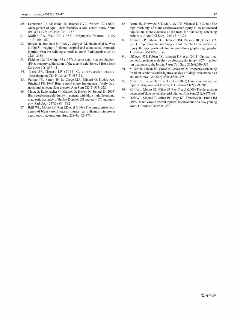
80. Lennarson PJ, Mostafavi H, Traynelis VC, Walters BC (2000)Management of type II dens fractures: a case–control study. Spine(Phila Pa 1976) 25(10):1234–1237
81. Mollan RA, Watt PC (1982) Hangman’s fracture. Injury14(3):265–267
82. Riascos R, Bonfante E, Cotes C, Guirguis M, Hakimelahi R, WestC (2015) Imaging of atlanto-occipital and atlantoaxial traumaticinjuries: what the radiologist needs to know. Radiographics 35(7):2121–2134
83. Fielding JW, Hawkins RJ (1977) Atlanto-axial rotatory fixation.(Fixed rotatory subluxation of the atlanto-axial joint). J Bone JointSurg Am 59(1):37–44
84. Nace SR, Gentry LR (2014) Cerebrovascular trauma.Neuroimaging Clin N Am 24(3):487–511
85. Fabian TC, Patton JH Jr, Croce MA, Minard G, Kudsk KA,Pritchard FE (1996) Blunt carotid injury. Importance of early diag-nosis and anticoagulant therapy. Ann Surg 223(5):513–522
86. Mutze S, Rademacher G, Matthes G, Hosten N, Stengel D (2005)Blunt cerebrovascular injury in patients with blunt multiple trauma:diagnostic accuracy of duplex Doppler US and early CT angiogra-phy. Radiology 237(3):884–892
87. Biffl WL, Moore EE, Ryu RK et al (1998) The unrecognized epi-demic of blunt carotid arterial injuries: early diagnosis improvesneurologic outcome. Ann Surg 228(4):462–470
88. Berne JD, Norwood SH, McAuley CE, Villareal DH (2001) Thehigh morbidity of blunt cerebrovascular injury in an unscreenedpopulation: more evidence of the need for mandatory screeningprotocols. J Am Coll Surg 192(3):314–321
89. Emmett KP, Fabian TC, DiCocco JM, Zarzaur BL, Croce MA(2011) Improving the screening criteria for blunt cerebrovascularinjury: the appropriate role for computed tomography angiography.J Trauma 70(5):1058–1063
90. DiCocco JM, Fabian TC, Emmett KP et al (2011) Optimal out-comes for patients with blunt cerebrovascular injury (BCVI): tailor-ing treatment to the lesion. J Am Coll Surg 212(4):549–557
91. Miller PR, Fabian TC, CroceMA et al (2002) Prospective screeningfor blunt cerebrovascular injuries: analysis of diagnostic modalitiesand outcomes. Ann Surg 236(3):386–393
92. Miller PR, Fabian TC, Bee TK et al (2001) Blunt cerebrovascularinjuries: diagnosis and treatment. J Trauma 51(2):279–285
93. Biffl WL, Moore EE, Elliott JP, Ray C et al (2000) The devastatingpotential of blunt vertebral arterial injuries. Ann Surg 231(5):672–681
94. BifflWL,Moore EE, Offner PJ, Brega KE, Franciose RJ, Burch JM(1999) Blunt carotid arterial injuries: implications of a new gradingscale. J Trauma 47(5):845–853
Insights Imaging (2017) 8:29–47 47