Embed Size (px)
Citation preview

PWSD
Portcullis House
Cradle Runway Remedial Works
PWSD
Portcullis House
Cradle Runway Remedial Works September 2010
This report takes into account the
particular instructions and requirements of our client. It is not intended for and should not be relied upon by any third party and no responsibility is undertaken to any third partyOve Arup & Partners Ltd
13 Fitzroy Street, London W1T 4BQ Tel +44 (0)20 7636 1531 Fax +44 (0)20 775 5 3673 www.arup.com
Job number 55720-54

PWSD Portcullis HouseCradle Runway Remedial Works
J:\...\REPLACEMENT WORKS 2008\0001CRADLE RUNWAY REMEDIALS.DOC 001
Ove Arup & Partners LtdISSUE 14/09/2010
Contents
Page 1 Introduction 2
2 Arup Visual Inspection 2006 3
3 Arup Inspection 2008 6
4 Thermal Movements and Jointing System in the Cradle Rails 8
5 Issues with the System 11
6 Option A: Cradle System Fully Operable 12
7 Option B: Cradle Rail System Made Safe 17

J:\040000\040200\40220\55720-54 TURRET BOLTS\REPLACEMENT WORKS 2008\0001CRADLE RUNWAY REMEDIALS.DOC
Page 1 Ove Arup & Partners LtdISSUE 14/09/2010
Executive Summary The Portcullis House cradle runway system around the outside and inner courtyard of the building is not currently used and have never been load tested or certified for use. This report summarises the history, explains in detail the deficiencies of the system and suggests two possible remedial options.
Movement joints in the rails have not been able to act as originally designed. In hot and cold weather the metal tracks have expanded/contracted with little freedom to move. This has caused permanent displacement of the tracks and bolt failures at the connections and splices. There is much evidence which shows that the track has been poorly constructed; this has contributed to and possibly caused some of the movement joints to become effectively locked.
A previous inspection of the cradle in 2006 catalogued approximately 170 individual problems with the system. A further review and limited inspection in 2008 confirmed the scale of the deficiencies. As a consequence we have outlined two possible options that give PWSD a choice over the extent of the remedial works.
The first option (option A) outlines what work is required such that the cradle runway system is reinstated so the runway beams can be load tested and certified suitable for use. The exact scope of works is dependant on site conditions and as such cannot be fully defined in this report. It is extensive and will require a full access system beneath the cradle runway both inside the courtyard and outside the building.
The second option (option B) is a minimum spend option which would make the existing runway beams safe as they stand but not operable i.e. undertake the minimum works intended to safeguard against further bolts failing and dropping out. If this option is chosen the current method of window cleaning and maintenance (abseiling) will be required to continue.
J:\040000\040200\40220\55720-54 TURRET BOLTS\REPLACEMENT WORKS 2008\0001CRADLE RUNWAY REMEDIALS.DOC
Page 2 Ove Arup & Partners LtdISSUE 14/09/2010
1 Introduction Historically there have been problems with the cradle runway system since its installation that have meant that the runway has never been load tested and certified as safe for use.
We understand that problems were identified shortly after its installation with bolts breaking or working loose during trial runs of the cradles round the track, and that more bolts fell from the runway system during a subsequent period of hot weather one summer.
We also understand that after discussions with the cradle supplier a fairly extensive replacement of the runway bolts was carried out in late 2000, early 2001. Even after these bolt replacement works the cradle supplier declined to carry out the proof load test that is required as part of the certification process before the cradle system can be used.
The installation short comings have meant that the system could not be commissioned and the cradle cleaning system can not be used. PWSD has requested Arup to consider the means by which the system could be repaired, reinstated and made safe and/or brought into service. This report describes the history of the installation, examines the structural problems with the system and outlines two different remedial options available to PWSD.
J:\040000\040200\40220\55720-54 TURRET BOLTS\REPLACEMENT WORKS 2008\0001CRADLE RUNWAY REMEDIALS.DOC
Page 3 Ove Arup & Partners LtdISSUE 14/09/2010
2 Arup Visual Inspection 2006 Arup was appointed to carry out an inspection of the runway system (as part of a wider inspection of roof structures) in 2006 and this is documented in ‘Portcullis House – 2006 Bolt Inspection, Inspection Report’, May 2006.
The aim of the report was to identify the source/cause of bolt failures and enable further discussion to be held regarding the possible failure mechanisms of the bolts.
In terms of the cradle system it concluded that:
• 32 no bolts were missing from the runway rail connections (approximately 1064 bolts in total).
• There was outward displacement (i.e. away from the building) of external runway at the corners of the building with all connections at the corner indicating outward movement. The cause of this movement was not clear.
• There were numerous incidents of poorly fitting steelwork with bolt holes drilled in incorrect locations, roller slots gouged out to allow bolts to fit and large amounts of packing, especially at the building corners.
No pattern to the missing bolts was noted and they were attributed to a combination of failures, namely: bolts not installed during construction and incorrectly tightened during construction.
The report provided a written description of the condition observed at each of the 656 connection points on the runway system and 101 photographs that show a catalogue of installation deficiencies.
The deficiencies mean that the installation is not in accordance with the initial design intent/specification and is the likely cause for its use being questioned by the cradle supplier/installer. Such is the condition described in the Inspection Report that the doubts raised by the supplier/installer may have about the systems performance in use would appear to be well founded.
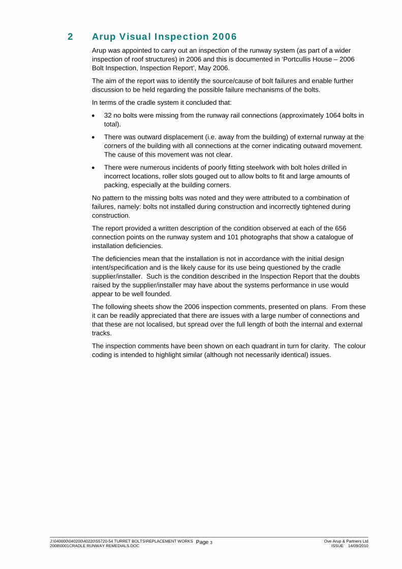
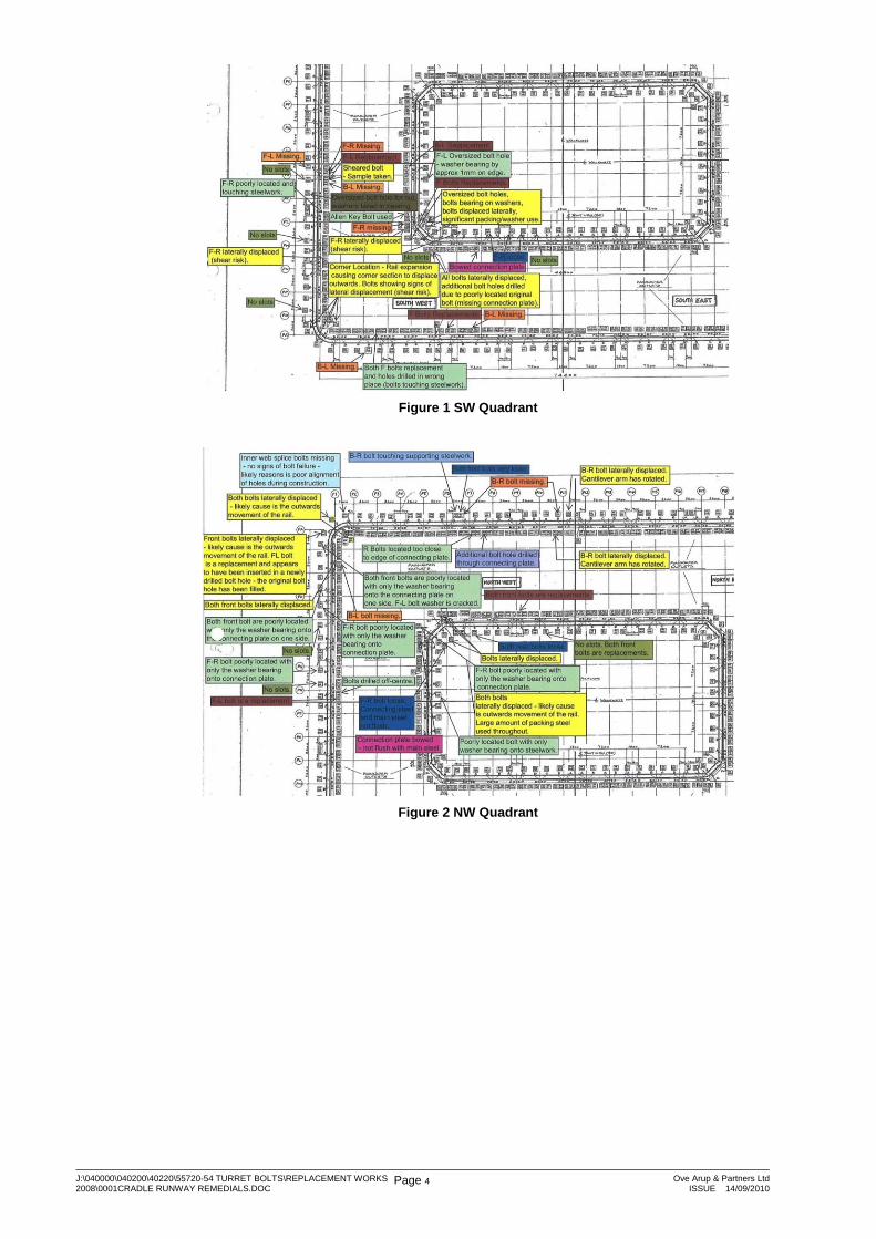
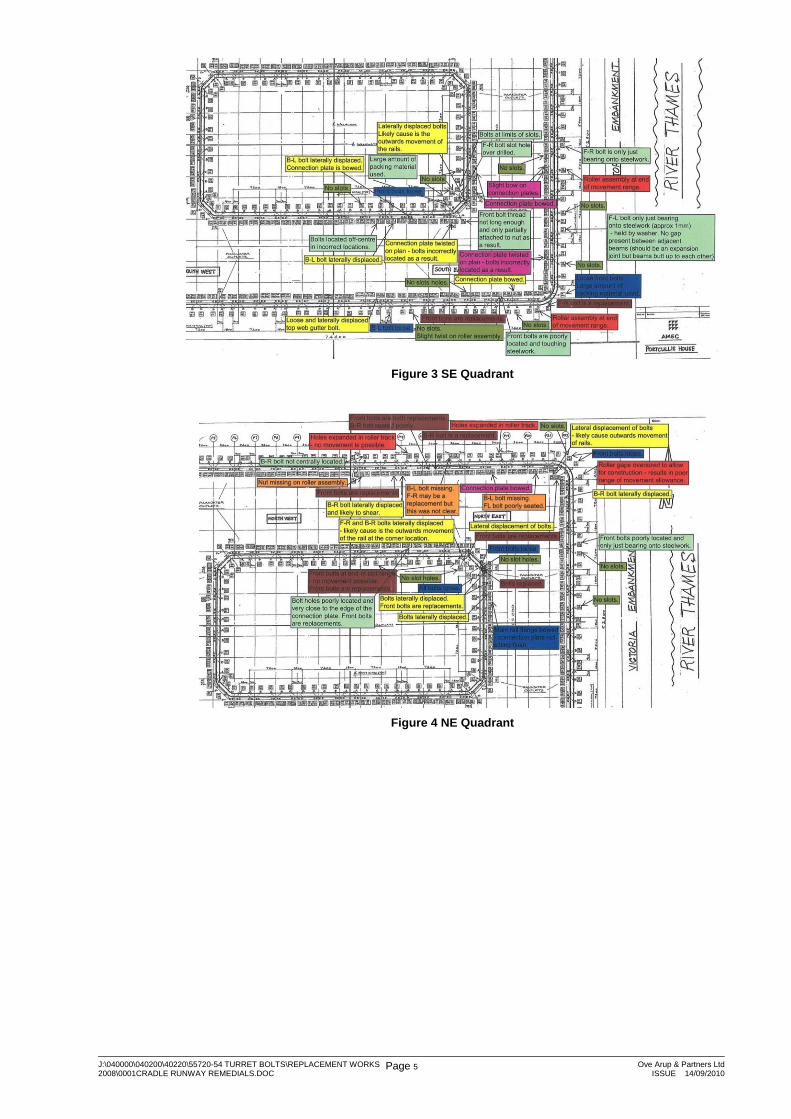
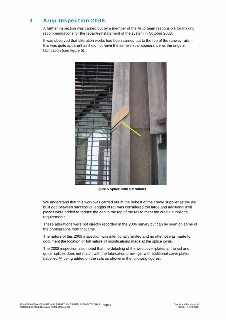
The following sheets show the 2006 inspection comments, presented on plans. From these it can be readily appreciated that there are issues with a large number of connections and that these are not localised, but spread over the full length of both the internal and external tracks.
The inspection comments have been shown on each quadrant in turn for clarity. The colour coding is intended to highlight similar (although not necessarily identical) issues.
J:\040000\040200\40220\55720-54 TURRET BOLTS\REPLACEMENT WORKS 2008\0001CRADLE RUNWAY REMEDIALS.DOC
Page 4 Ove Arup & Partners LtdISSUE 14/09/2010
Figure 1 SW Quadrant
Figure 2 NW Quadrant
J:\040000\040200\40220\55720-54 TURRET BOLTS\REPLACEMENT WORKS 2008\0001CRADLE RUNWAY REMEDIALS.DOC
Page 5 Ove Arup & Partners LtdISSUE 14/09/2010
Figure 3 SE Quadrant
Figure 4 NE Quadrant
J:\040000\040200\40220\55720-54 TURRET BOLTS\REPLACEMENT WORKS 2008\0001CRADLE RUNWAY REMEDIALS.DOC
Page 6 Ove Arup & Partners LtdISSUE 14/09/2010
3 Arup Inspection 2008 A further inspection was carried out by a member of the Arup team responsible for making recommendations for the repair/reinstatement of the system in October 2008.
It was observed that alteration works had been carried out to the top of the runway rails – this was quite apparent as it did not have the same visual appearance as the original fabrication (see figure 5).
Figure 5 Splice Infill alterations
We understand that this work was carried out at the behest of the cradle supplier as the as-built gap between successive lengths of rail was considered too large and additional infill pieces were added to reduce the gap in the top of the rail to meet the cradle supplier’s requirements.
These alterations were not directly recorded in the 2006 survey but can be seen on some of the photographs from that time.
The nature of this 2008 inspection was intentionally limited and no attempt was made to document the location or full nature of modifications made at the splice joints.
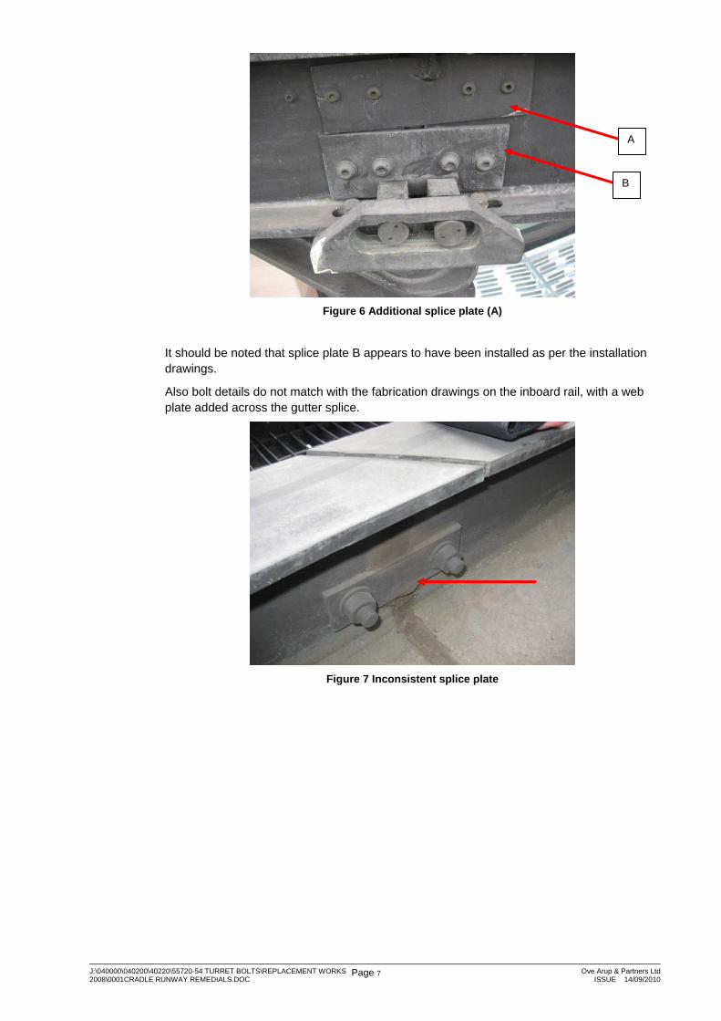
The 2008 inspection also noted that the detailing of the web cover-plates at the rail and gutter splices does not match with the fabrication drawings, with additional cover plates (labelled A) being added on the rails as shown in the following figures:
J:\040000\040200\40220\55720-54 TURRET BOLTS\REPLACEMENT WORKS 2008\0001CRADLE RUNWAY REMEDIALS.DOC
Page 7 Ove Arup & Partners LtdISSUE 14/09/2010
Figure 6 Additional splice plate (A)
It should be noted that splice plate B appears to have been installed as per the installation drawings.
Also bolt details do not match with the fabrication drawings on the inboard rail, with a web plate added across the gutter splice.
Figure 7 Inconsistent splice plate
A
B
J:\040000\040200\40220\55720-54 TURRET BOLTS\REPLACEMENT WORKS 2008\0001CRADLE RUNWAY REMEDIALS.DOC
Page 8 Ove Arup & Partners LtdISSUE 14/09/2010
4 Thermal Movements and Jointing System in the Cradle Rails 4.1 Introduction
The anecdotal evidence for the historic causes of bolt failure point to:
i. Running the cradle on the rails
ii. Summer temperatures
That elevated temperatures cause so many bolts to fail strongly suggests that the splice/movement joint details have been compromised.
The splice/movement joint system shown on the Arup drawings is described later in this chapter and provides two 8mm wide open joints in every 9m length of the building. Calculations of predicted thermal movements (describes later in this chapter) suggest that these 8mm joints might open up or close by 3.7mm.
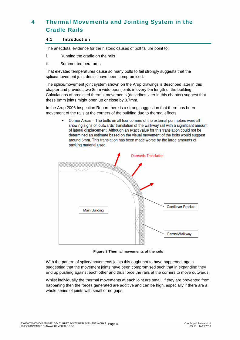
In the Arup 2006 Inspection Report there is a strong suggestion that there has been movement of the rails at the corners of the building due to thermal effects.
Figure 8 Thermal movements of the rails
With the pattern of splice/movements joints this ought not to have happened, again suggesting that the movement joints have been compromised such that in expanding they end up pushing against each other and thus force the rails at the corners to move outwards.
Whilst individually the thermal movements at each joint are small, if they are prevented from happening then the forces generated are additive and can be high, especially if there are a whole series of joints with small or no gaps.
J:\040000\040200\40220\55720-54 TURRET BOLTS\REPLACEMENT WORKS 2008\0001CRADLE RUNWAY REMEDIALS.DOC
Page 9 Ove Arup & Partners LtdISSUE 14/09/2010
4.2 The Jointing System
The splice movement joint system is described on the Arup drawings as follows:
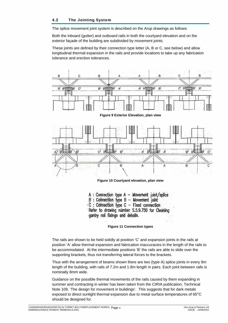
Both the inboard (gutter) and outboard rails in both the courtyard elevation and on the exterior façade of the building are subdivided by movement joints.
These joints are defined by their connection type letter (A, B or C, see below) and allow longitudinal thermal expansion in the rails and provide locations to take up any fabrication tolerance and erection tolerances.
Figure 9 Exterior Elevation, plan view
Figure 10 Courtyard elevation, plan view
Figure 11 Connection types
The rails are shown to be held solidly at position ‘C’ and expansion joints in the rails at position ‘A’ allow thermal expansion and fabrication inaccuracies in the length of the rails to be accommodated. At the intermediate positions ‘B’ the rails are able to slide over the supporting brackets, thus not transferring lateral forces to the brackets.
Thus with the arrangement of beams shown there are two (type A) splice joints in every 9m length of the building, with rails of 7.2m and 1.8m length in pairs. Each joint between rails is nominally 8mm wide.
Guidance on the possible thermal movements of the rails caused by them expanding in summer and contracting in winter has been taken from the CIRIA publication, Technical Note 109, ‘The design for movement in buildings’. This suggests that for dark metals exposed to direct sunlight thermal expansion due to metal surface temperatures of 65°C should be designed for.
J:\040000\040200\40220\55720-54 TURRET BOLTS\REPLACEMENT WORKS 2008\0001CRADLE RUNWAY REMEDIALS.DOC
Page 10 Ove Arup & Partners LtdISSUE 14/09/2010
Similarly for extreme cold temperatures a case of -25°C should be designed for.
Consistent with normal practise the fabricator should have set the rail lengths based on a temperature of 20°C, which then gives a thermal range of +/- 45°C that might cause the joints to open or close from this 8mm width.
This 45°C change in temperature on the 7.2mm rail would cause 5.8mm of movement, 2.9mm at each end. Similarly on the 1.8m long rail the values are less than 1.6mm overall, giving 0.8mm at each end.
Thus at these extreme temperature conditions each 8mm joint might open up or close by 3.7mm.
The movement joints provided should therefore be sufficient and will also cater for any fabrication and/or erection tolerances that may exist.
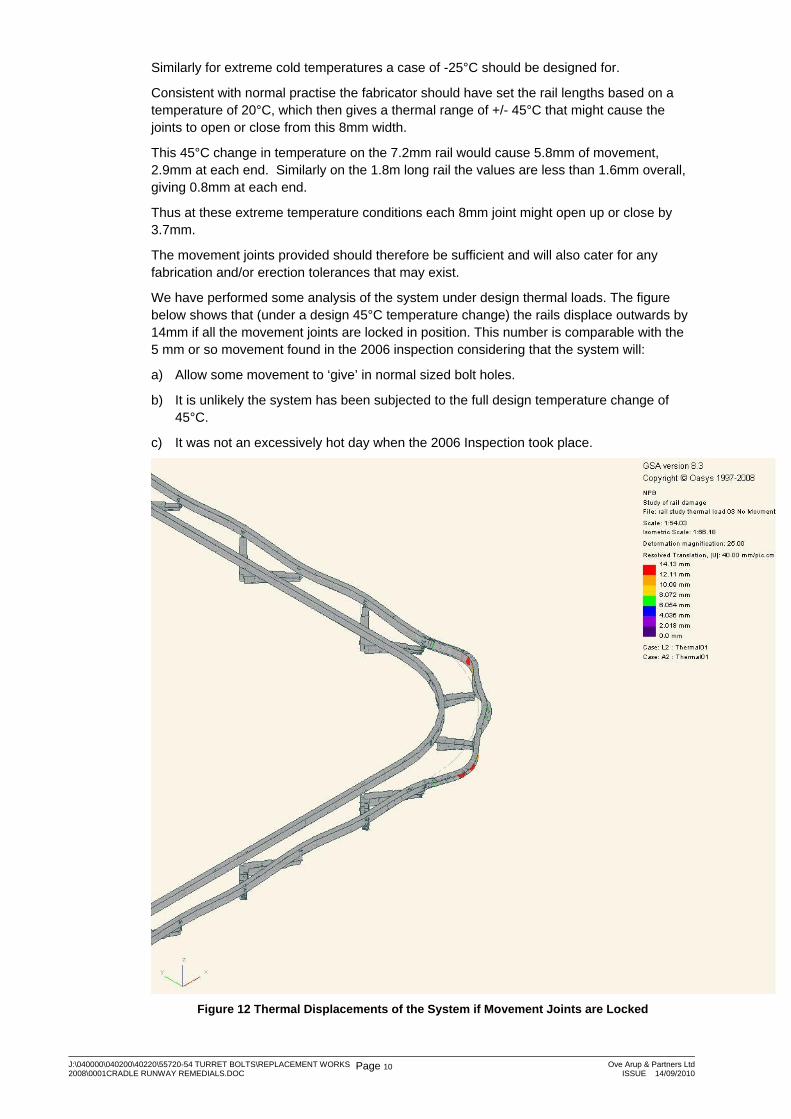
We have performed some analysis of the system under design thermal loads. The figure below shows that (under a design 45°C temperature change) the rails displace outwards by 14mm if all the movement joints are locked in position. This number is comparable with the 5 mm or so movement found in the 2006 inspection considering that the system will:
a) Allow some movement to ‘give’ in normal sized bolt holes.
b) It is unlikely the system has been subjected to the full design temperature change of 45°C.
c) It was not an excessively hot day when the 2006 Inspection took place.
Figure 12 Thermal Displacements of the System if Movement Joints are Locked
J:\040000\040200\40220\55720-54 TURRET BOLTS\REPLACEMENT WORKS 2008\0001CRADLE RUNWAY REMEDIALS.DOC
Page 11 Ove Arup & Partners LtdISSUE 14/09/2010
5 Issues with the System The problems with the system are three-fold and are described as follows.
1) Fabrication and/or installation deficiencies which will likely affect the running and performance of the cradle.
2) Permanent damage to the system which has occurred because the movement joints have become locked
3) Damage which may happen in the future (e.g. bolts failing) because the movement joints remain locked.
In many cases it is difficult to understand what has caused the deficiencies. For example, are the bolt holes misaligned because the members were fabricated/installed incorrectly or because permanent deformation has occurred due to thermal movements?
Two remedial options are set out in the following sections. The first is the work we believe necessary to make the Cradle system operable e.g. fix 1), 2) and prevent 3) from happening. The second is the minimum amount of work we consider necessary to safeguard against further bolt failures and components dropping from the system e.g. prevent 3) from occurring.
The remedial works have been separated in this manner as the extent of the work required to make the system operable is considerable and PWSD may wish to consider a ‘minimum spend’ option that does not fix the cradle but ensures the system is safeguarded against further bolt failures.
Identifying the two levels of remedial works will enable PWSD to consider the cost/benefits of carrying out more limited work and continuing with the current methods of window cleaning, maintenance etc. (e.g. abseiling) versus carrying out the full remedial works to bring the cradle into service.
In summary, a description of the two options is:
Option A: Cradle system fully repaired and reinstated so the runway beams can be load tested and certified suitable for use.
Option B: Cradle rail system made safe but not made operable
J:\040000\040200\40220\55720-54 TURRET BOLTS\REPLACEMENT WORKS 2008\0001CRADLE RUNWAY REMEDIALS.DOC
Page 12 Ove Arup & Partners LtdISSUE 14/09/2010
6 Option A: Cradle System Fully Operable The works described for this option will permit the cradle runway system to be reinstated so the runway beams can be load tested and certified suitable for use as part of the overall system.
The remedial works require the cradle runway beams to be installed to their originally specified condition whereby all deficiencies and defects are to be corrected.
The specification of remedial works is currently at an outline level to cover the general defects and problems. A detailed specification would be developed to cover the full range of defects noted/observed.
To carry out the following remedial works we believe that an extensive access system beneath the cradle runway (both inside the courtyard and outside the building) will be required.
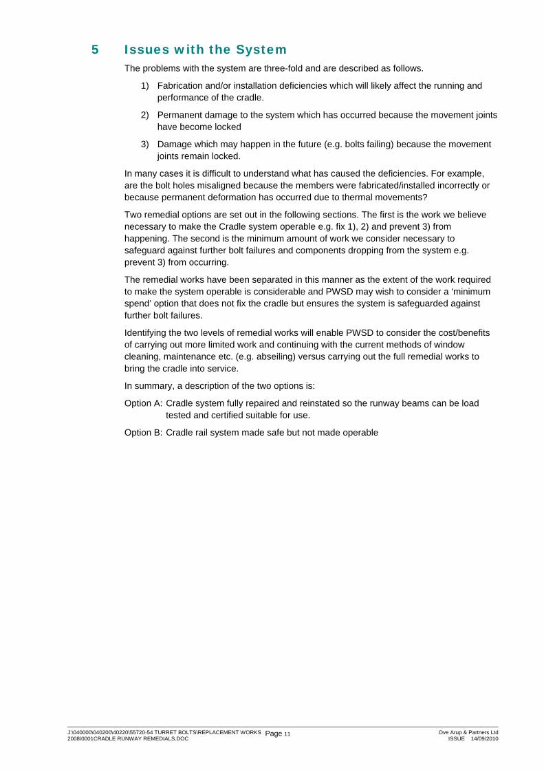
The setting out of the installed beams will need to meet the requirements of the cradle supplier (vertical and horizontal alignment, spacing between the rails, maximum gap sizes at rail splices etc.).
Figure 13 Previous remedial at gap
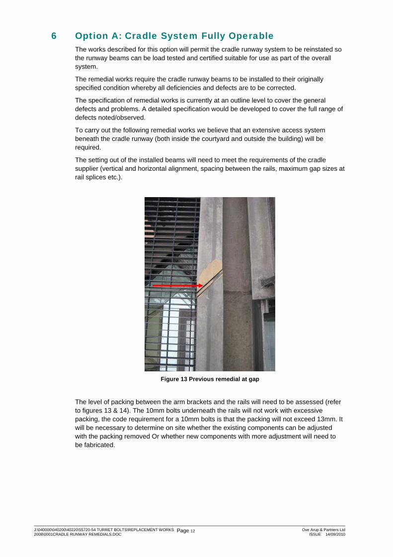
The level of packing between the arm brackets and the rails will need to be assessed (refer to figures 13 & 14). The 10mm bolts underneath the rails will not work with excessive packing, the code requirement for a 10mm bolts is that the packing will not exceed 13mm. It will be necessary to determine on site whether the existing components can be adjusted with the packing removed Or whether new components with more adjustment will need to be fabricated.
J:\040000\040200\40220\55720-54 TURRET BOLTS\REPLACEMENT WORKS 2008\0001CRADLE RUNWAY REMEDIALS.DOC
Page 13 Ove Arup & Partners LtdISSUE 14/09/2010
Figure 14 Typical Excessive Packing
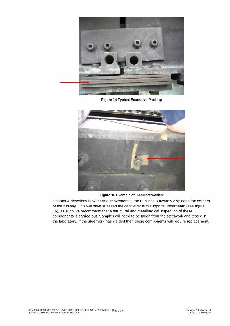
Figure 15 Example of incorrect washer
Chapter 4 describes how thermal movement in the rails has outwardly displaced the corners of the runway. This will have stressed the cantilever arm supports underneath (see figure 16), as such we recommend that a structural and metallurgical inspection of these components is carried out. Samples will need to be taken from the steelwork and tested in the laboratory. If the steelwork has yielded then these components will require replacement.
J:\040000\040200\40220\55720-54 TURRET BOLTS\REPLACEMENT WORKS 2008\0001CRADLE RUNWAY REMEDIALS.DOC
Page 14 Ove Arup & Partners LtdISSUE 14/09/2010
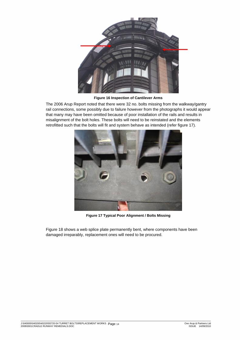
Figure 16 Inspection of Cantilever Arms
The 2006 Arup Report noted that there were 32 no. bolts missing from the walkway/gantry rail connections, some possibly due to failure however from the photographs it would appear that many may have been omitted because of poor installation of the rails and results in misalignment of the bolt holes. These bolts will need to be reinstated and the elements retrofitted such that the bolts will fit and system behave as intended (refer figure 17).
Figure 17 Typical Poor Alignment / Bolts Missing
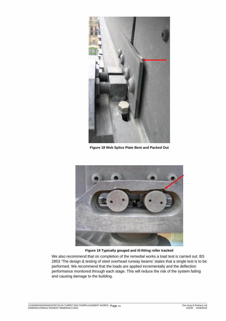
Figure 18 shows a web splice plate permanently bent, where components have been damaged irreparably, replacement ones will need to be procured.
J:\040000\040200\40220\55720-54 TURRET BOLTS\REPLACEMENT WORKS 2008\0001CRADLE RUNWAY REMEDIALS.DOC
Page 15 Ove Arup & Partners LtdISSUE 14/09/2010
Figure 18 Web Splice Plate Bent and Packed Out
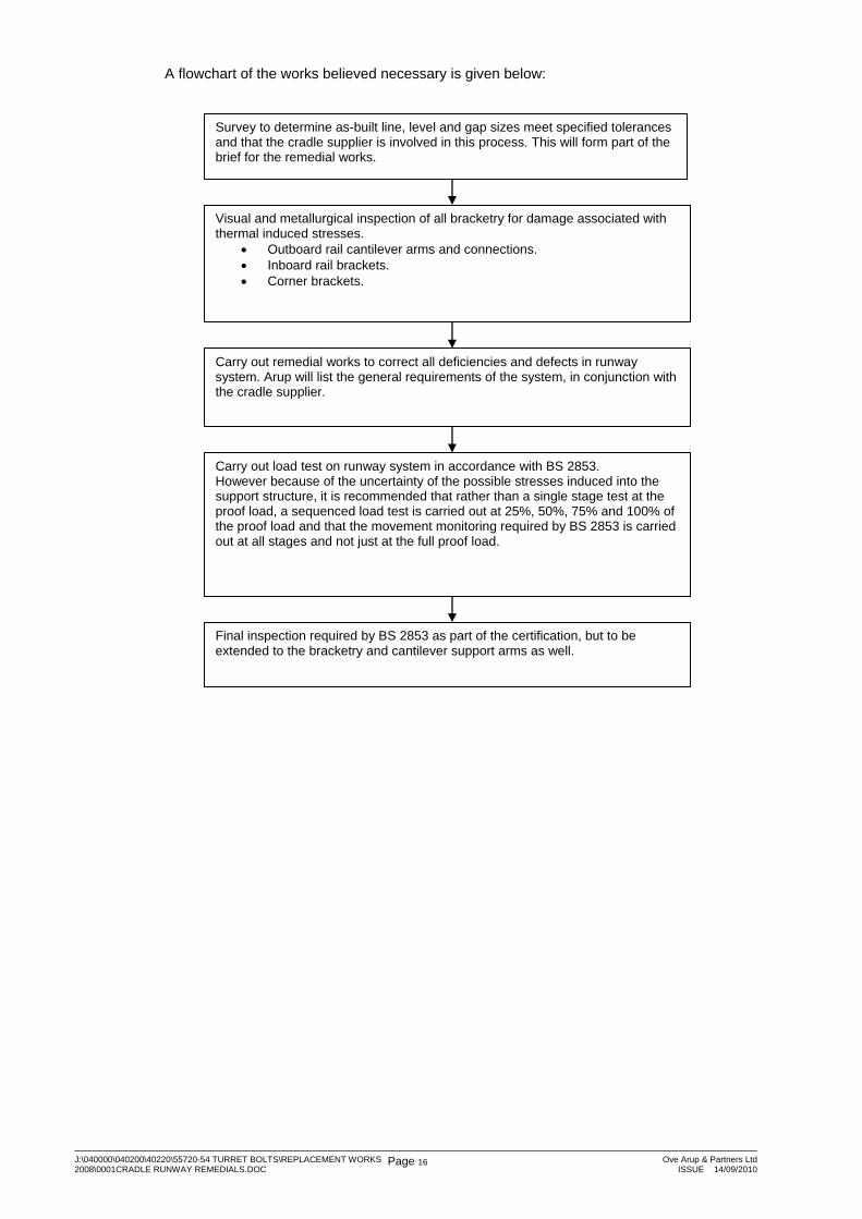
Figure 19 Typically gouged and ill-fitting roller tracked
We also recommend that on completion of the remedial works a load test is carried out. BS 2853 ‘The design & testing of steel overhead runway beams’ states that a single test is to be performed. We recommend that the loads are applied incrementally and the deflection performance monitored through each stage. This will reduce the risk of the system failing and causing damage to the building.
J:\040000\040200\40220\55720-54 TURRET BOLTS\REPLACEMENT WORKS 2008\0001CRADLE RUNWAY REMEDIALS.DOC
Page 16 Ove Arup & Partners LtdISSUE 14/09/2010
A flowchart of the works believed necessary is given below:
Visual and metallurgical inspection of all bracketry for damage associated with thermal induced stresses.
• Outboard rail cantilever arms and connections. • Inboard rail brackets. • Corner brackets.
Carry out remedial works to correct all deficiencies and defects in runway system. Arup will list the general requirements of the system, in conjunction with the cradle supplier.
Carry out load test on runway system in accordance with BS 2853. However because of the uncertainty of the possible stresses induced into the support structure, it is recommended that rather than a single stage test at the proof load, a sequenced load test is carried out at 25%, 50%, 75% and 100% of the proof load and that the movement monitoring required by BS 2853 is carried out at all stages and not just at the full proof load.
Final inspection required by BS 2853 as part of the certification, but to be extended to the bracketry and cantilever support arms as well.
Survey to determine as-built line, level and gap sizes meet specified tolerances and that the cradle supplier is involved in this process. This will form part of the brief for the remedial works.
J:\040000\040200\40220\55720-54 TURRET BOLTS\REPLACEMENT WORKS 2008\0001CRADLE RUNWAY REMEDIALS.DOC
Page 17 Ove Arup & Partners LtdISSUE 14/09/2010
7 Option B: Cradle Rail System Made Safe 7.1 Introduction
The specification for the works for this option will result in the existing runway beams being made secure. This would be the minimum works required to safeguard against bolts failing and dropping out. They would not allow the system to operate.
The walkway system would be adequate for general pedestrian maintenance access. This level of work is means it is implicit that the cradles are immobilised and not operated.
Thus the aim of Option B is to guard against the build up of thermally induced forces by carrying out work to the splice connections so that thermal movements can occur.
The scale of this work is therefore significantly less than required for the Option A remedial works.
There are 56 splice joints around the external elevations of the building and 28 on the courtyard elevations, with an inspection required for both the outboard rail and the inboard gutter/rail at each location.
At these splice connections the remedials are not intended to put right all of the deficiencies noted in the inspection report, simply those necessary to make the runway beams safe as they stand by releasing movement joints.
It is considered that these works are comparatively simple and can largely be done from the access walkway.
The following is a description of the required remedial works for option B:
The only works considered necessary are at the splice joints at the end of each rail.
In essence these works need to make sure that there is an adequate clear gap between successive rails and that the rails are free to expand or contract at these points.
7.2 Splice Joints
7.2.1 Gap widths It will be necessary is to check the sizes of all the gaps in the rails and the gutter and remedial works are carried out to provide a minimum of 3mm open joint at each splice position.
It is noted that the 2006 Arup Inspection did not highlight any particular areas where inadequate width splice joints were found.
When the joints gaps are insufficient it may be possible to even out the joints by physically repositioning the short 1.8m long rails, slackening off the support bolts and sliding into a better position.
Where this will still not provide an adequate width of joint might it be necessary to undertake local cutting to the short members to provide the clear joint prescribed.
For the inboard rail and gutter it may be necessary to lift the 1.8m long rails out of the supporting shoe castings if cutting is required.
7.2.2 Freedom at the splices Consideration also needs to be given to the support of the rails at the splice locations, to make sure that the thermal movements are not constrained through the support brackets by solid connection of the rail to the supporting bracket.
7.2.3 Connection to the support plate On the outboard rails there are slotted holes in the bottom flange of the rail. These slots occur on both sides of the web. Access to one side can only be achieved by lifting the walkway grating.
J:\040000\040200\40220\55720-54 TURRET BOLTS\REPLACEMENT WORKS 2008\0001CRADLE RUNWAY REMEDIALS.DOC
Page 18 Ove Arup & Partners LtdISSUE 14/09/2010
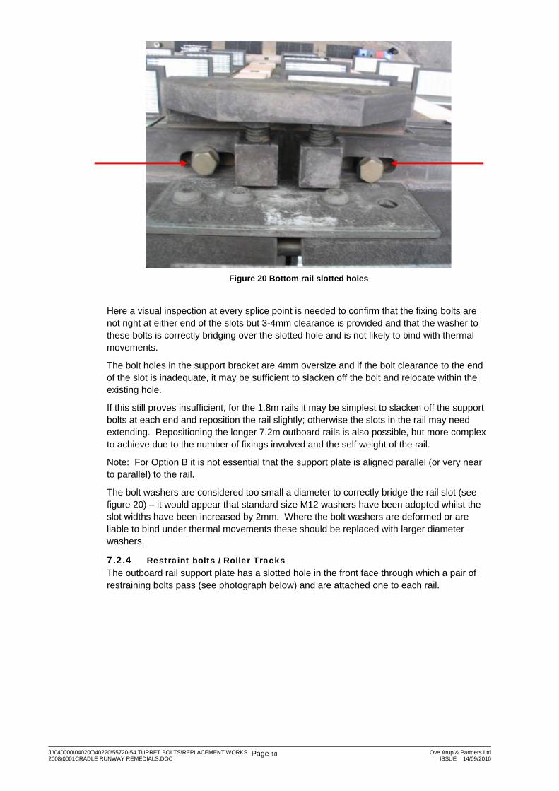
Figure 20 Bottom rail slotted holes
Here a visual inspection at every splice point is needed to confirm that the fixing bolts are not right at either end of the slots but 3-4mm clearance is provided and that the washer to these bolts is correctly bridging over the slotted hole and is not likely to bind with thermal movements.
The bolt holes in the support bracket are 4mm oversize and if the bolt clearance to the end of the slot is inadequate, it may be sufficient to slacken off the bolt and relocate within the existing hole.
If this still proves insufficient, for the 1.8m rails it may be simplest to slacken off the support bolts at each end and reposition the rail slightly; otherwise the slots in the rail may need extending. Repositioning the longer 7.2m outboard rails is also possible, but more complex to achieve due to the number of fixings involved and the self weight of the rail.
Note: For Option B it is not essential that the support plate is aligned parallel (or very near to parallel) to the rail.
The bolt washers are considered too small a diameter to correctly bridge the rail slot (see figure 20) – it would appear that standard size M12 washers have been adopted whilst the slot widths have been increased by 2mm. Where the bolt washers are deformed or are liable to bind under thermal movements these should be replaced with larger diameter washers.
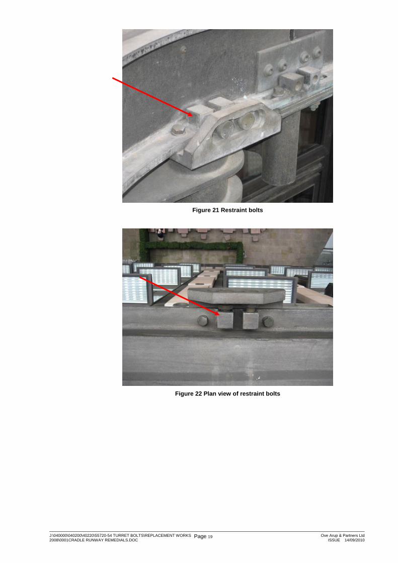
7.2.4 Restraint bolts / Roller Tracks The outboard rail support plate has a slotted hole in the front face through which a pair of restraining bolts pass (see photograph below) and are attached one to each rail.
J:\040000\040200\40220\55720-54 TURRET BOLTS\REPLACEMENT WORKS 2008\0001CRADLE RUNWAY REMEDIALS.DOC
Page 19 Ove Arup & Partners LtdISSUE 14/09/2010
Figure 21 Restraint bolts
Figure 22 Plan view of restraint bolts
J:\040000\040200\40220\55720-54 TURRET BOLTS\REPLACEMENT WORKS 2008\0001CRADLE RUNWAY REMEDIALS.DOC
Page 20 Ove Arup & Partners LtdISSUE 14/09/2010
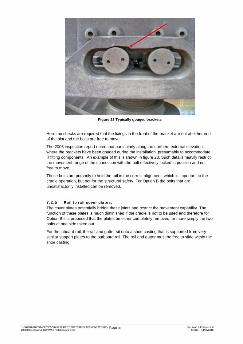
Figure 23 Typically gouged brackets
Here too checks are required that the fixings in the front of the bracket are not at either end of the slot and the bolts are free to move.
The 2006 inspection report noted that particularly along the northern external elevation where the brackets have been gouged during the installation, presumably to accommodate ill fitting components. An example of this is shown in figure 23. Such details heavily restrict the movement range of the connection with the bolt effectively locked in position and not free to move.
These bolts are primarily to hold the rail in the correct alignment, which is important to the cradle operation, but not for the structural safety. For Option B the bolts that are unsatisfactorily installed can be removed.
7.2.5 Rail to rail cover plates. The cover plates potentially bridge these joints and restrict the movement capability. The function of these plates is much diminished if the cradle is not to be used and therefore for Option B it is proposed that the plates be either completely removed, or more simply the two bolts at one side taken out.
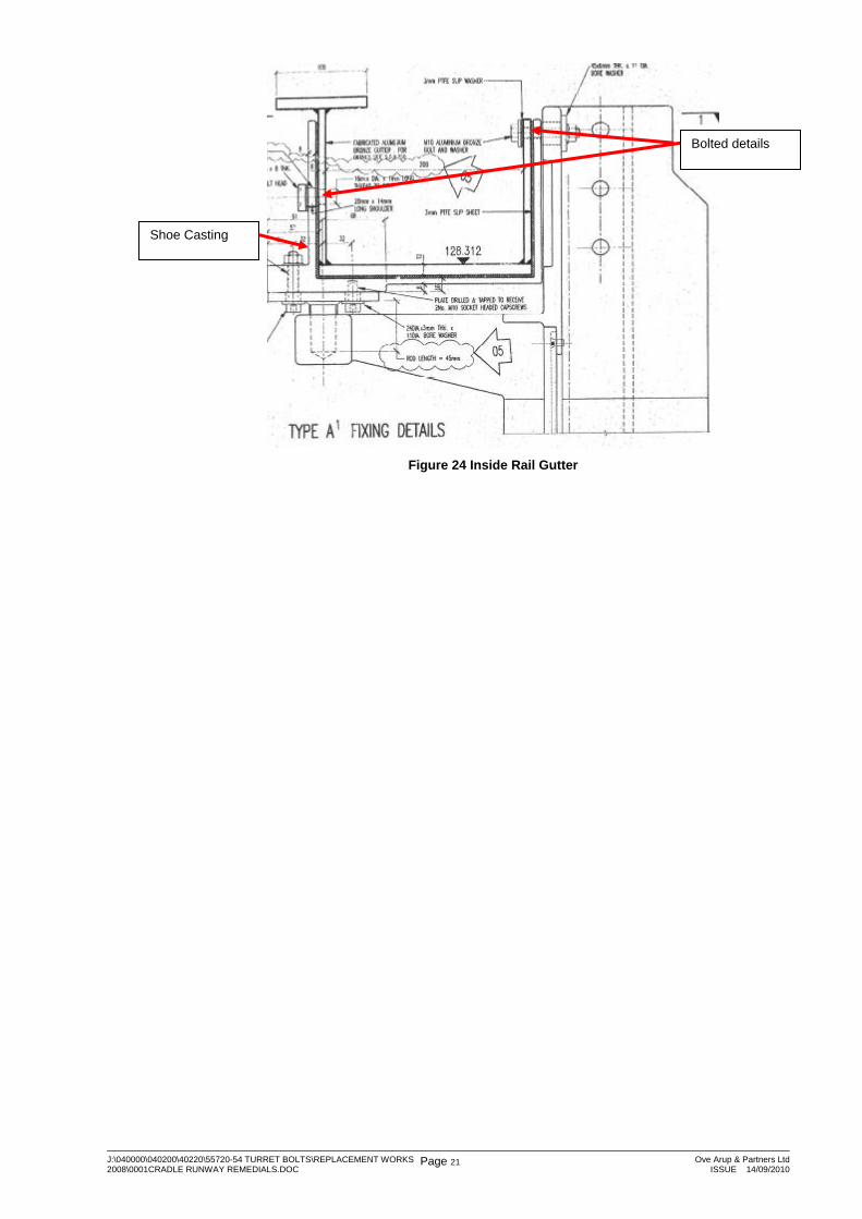
For the inboard rail, the rail and gutter sit onto a shoe casting that is supported from very similar support plates to the outboard rail. The rail and gutter must be free to slide within the shoe casting.
J:\040000\040200\40220\55720-54 TURRET BOLTS\REPLACEMENT WORKS 2008\0001CRADLE RUNWAY REMEDIALS.DOC
Page 21 Ove Arup & Partners LtdISSUE 14/09/2010
Figure 24 Inside Rail Gutter
Shoe Casting
Bolted details

J:\040000\040200\40220\55720-54 TURRET BOLTS\REPLACEMENT WORKS 2008\0001CRADLE RUNWAY REMEDIALS.DOC
Page 22 Ove Arup & Partners LtdISSUE 14/09/2010
Figure 25 Inside Rail
As noted earlier in this report it appears that the fixing bolt detail in the other gutter wall has been changed from that shown on the drawings. The detail actually employed can only be determined by loosening some of these bolts and removing the cover plates on either side.
Figure 26 Splice plate
The cover plates bridge these joints and restrict the movement capability. Again the need for these plates is diminished if the cradle is not to be used and therefore for Option B it is proposed that the bolt at one side taken out.
Visual inspection of the fixing bolts on the gutter wall closest to the building is required to check the bolts are not at either end of their slots. If there is less than 3-4mm clearance it may be sufficient to slacken off the fixings and relocate them within the bolt holes.
Outside face of Shoe Casting below rail

J:\040000\040200\40220\55720-54 TURRET BOLTS\REPLACEMENT WORKS 2008\0001CRADLE RUNWAY REMEDIALS.DOC
Page 23 Ove Arup & Partners LtdISSUE 14/09/2010
7.3 Summary of Option B Remedial Works
The following is a summary of the work required to make the cradle rail system safe but not made operable.
7.3.1 Outboard rails splice locations • Where the open gaps between adjacent rails is less than of 3mm or 4mm open the joint
by either repositioning the 1.8m long beams or by removing the web cover plates completely and saw cutting.
• Where fixing bolts are at either end of slotted holes in the rails they are slackened off and repositioned.
• Where washers are not bridging the rail slots correctly, the bolts are slacked and repositioned; it may also be necessary to use larger diameter washers.
• Where the fixings in the front of the bracket are at either end of these slot or the bolt is not free to move, remove the bolt altogether.
• The bolts on one side of the web cover plates are simply removed all together.
7.3.2 Inboard rail/gutter splice locations • Where the open gaps between adjacent gantry rails is less than of 3mm or 4mm open
the joint by removing the web cover plates completely and saw cutting.
• Undersize joints in the gutter itself will be individually assessed to determine if works are necessary.
• Where fixing bolts on the gutter wall closest to the building are at either end of their slots these are slackened of and repositioned.
• At the fixing bolt in the other gutter wall it is proposed to remove the bolts on one side of the splice connection.