Embed Size (px)
Citation preview
The Continuous Rheoconversion Process: Scale-up and
Optimization
A Thesis
Submitted to the Faculty
of the
WORCESTER POLYTECHNIC INSTITUTE
in partial fulfillment of the requirements for the
Degree of Master of Science
in
Materials Science and Engineering
May 2005
By
William J. Bernard, III
_______________________________
APPROVED:
_______________________________
Diran Apelian, Howmet Professor of Engineering, Advisor
_______________________________
Richard D. Sisson, Jr., Professor of Mechanical Engineering, Materials Science and
Engineering Program Head
ii
Abstract
Semi-solid metal (SSM) processing has emerged as a preferred manufacturing
method due to the superior quality associated with semi-solid castings. In recent years,
the driving force to reduce process cost has led to the development of a few rheocasting
(also termed slurry-on-demand) processes. These include UBE’s New Rheocasting
(NRC) process [1], Idra Prince’s Semi-Solid Rheocasting (SSR) process [2], and THT’s
Sub-Liquidus Casting (SLC®) process [3]. A novel slurry-making SSM process
developed at ACRC/MPI, termed the “Continuous Rheoconversion Process” (CRP), is a
passive liquid mixing technique in which the nucleation and growth of the primary phase
are controlled using a specially designed “reactor”. The reactor provides heat extraction,
copious nucleation and forced convection during the initial stage of solidification, leading
to the formation of thixotropic structures. In these studies, the critical issues/challenges
to optimize the CRP for industrial applications have been addressed through validation
experiments and pre-industrial trials.
iii
Acknowledgements
I would like to thank my thesis advisor, Prof. Diran Apelian, for his guidance and
support of my scholarly pursuits and my personal life over the past two years. As a
mentor and friend, he has helped steer me onto a path to a promising future.
Prof. Qingyue Pan also has been a wonderful advisor for this thesis. He was always
been available to help me, as well as explain phenomena more clearly to me.
I would also like to express my gratitude to Prof. Sisson, Prof. Makhlouf, and Prof.
Shivkumar for being such wonderful teachers. Each one is enthusiastic about their
subjects, and passionate about helping their students learn. Spending time in class with
each of them has been a privilege.
To the support staff of MPI, Carol Garofoli, Hailan Li, Betty Hale, Todor
Kiryazov, Maureen Plunkett, and Carl Raatikainen: thank you for always lending a
helping hand. Your efforts “behind the scenes” allowed me to do this work and present it
to a wide audience. You all are what make MPI such a great place.
Matt Findon, whose work this thesis is built upon, has always made himself
available to answer any questions I have had about his work. Brian Dewhirst has always
been willing to lend a helping ear or a discerning eye whenever I needed a comrade to
check what I was doing.
Joe Brooks and his excellent machining work deserve mention. Whenever Prof.
Pan or I needed help manufacturing our ideas, he was always very helpful and quick to
make what we needed.
I would like to dedicate this work in memory of my mother, Karen E. Bernard,
who always pushed me to maximize my academic potential.
iv
Table of Contents
The Continuous Rheoconversion Process: Scale-up and Optimization.............................. i
Abstract ............................................................................................................................... ii
Acknowledgements............................................................................................................ iii
Table of Contents............................................................................................................... iv
List of Figures and Tables................................................................................................... v
1. Introduction..................................................................................................................... 1
2. Background..................................................................................................................... 3
2.1 Emergence of SSM Processing................................................................................. 3
2.2 The Paradigm Shift in SSM Processing.................................................................... 9
2.3 Origins of the Continuous Rheoconversion Process (CRP) ................................... 13
3. Objectives ..................................................................................................................... 17
4. Experimental Methodology .......................................................................................... 19
4.1 Breakdown trials ..................................................................................................... 19
4.1.1 CRP Apparatus: One melt, tortuous reactor ................................................... 20
4.1.2 CRP Apparatus: One melt, no reactor............................................................. 22
4.1.3 CRP Apparatus: One melt, tubular reactors.................................................... 23
4.1.4 Sample Preparation and Microstructural Analysis .......................................... 25
4.2 Pre-industrial trials.................................................................................................. 26
4.2.1 Split Channel Plate........................................................................................... 28
4.2.2 Sloped Steel Tube ............................................................................................ 29
5. Results & Discussion .................................................................................................... 31
5.1 Breakdown Study.................................................................................................... 31
5.1.1 CRP Apparatus: One melt, tortuous reactor ................................................... 31
5.1.2 CRP Apparatus: One melt, no reactor............................................................. 34
5.1.3 CRP Apparatus: One melt, tubular reactor ..................................................... 36
5.2 Pre-industrial trials.................................................................................................. 39
5.2.1 Split Channel Plate........................................................................................... 40
5.2.2 Sloped Steel Tube ............................................................................................ 42
6. Conclusions................................................................................................................... 44
7. References..................................................................................................................... 46

v
List of Figures and Tables
Figure 1: Photograph of lab-scale CRP apparatus with important features highlighted... 14
Figure 2: CRP apparatus setups for breakdown trials: (A) one melt, torturous reactor, (B)
one melt, no reactor, and (C) one melt, tubular reactor. ....................................... 20
Figure 3: Diagram of tortuous reactor interior.................................................................. 21
Figure 4: Diagram of the “nipple” used in the one melt, tubular reactor trials................. 24
Figure 5: Diagram of location within casting from where microstructure derived .......... 26
Figure 6: Split channel plate reactor ................................................................................. 27
Figure 7: Sloped steel tube reactor................................................................................... 27
Figure 8: Trial 1 – grain refined alloy, tortuous reactor ................................................... 32
Figure 9: Trial 2 – non-grain refined alloy, tortuous reactor ........................................... 32
Figure 10: Trial 3 – grain refined alloy, no reactor.......................................................... 35
Figure 11: Trial 4 – non-grain refined alloy, no reactor .................................................. 35
Figure 12: Trial 5 – grain refined alloy, stainless steel tubular reactor ........................... 38
Figure 13: Trial 6 – grain refined alloy, copper tubular reactor ...................................... 38
Figure 14: Trial 7 – non-grain refined alloy, stainless steel tubular reactor .................... 38
Figure 15: Trial 6 – grain refined alloy, copper tubular reactor – remnant material stuck
within tube ............................................................................................................ 38
Figure 16: Trial A: 720ºC pour, no reactor..................................................................... 40
Figure 17: Microstructures obtained from trial B (split channel plate reactor) – B.1:
720ºC pour, B.2: 680ºC pour, B.3: 650ºC pour, B.4: 630ºC pour. ....................... 41
Figure 18: Microstructures obtained from trial C (sloped steel tube reactor) – C.1: 720ºC
pour, C.2: 680ºC pour, C.3: 650ºC pour, C.4: 630ºC pour. .................................. 43
Table 1: Variables in the CRP .......................................................................................... 15
Table 2: Summary of breakdown trials............................................................................. 19
Table 3: Alloy compositions used in the breakdown trials............................................... 21
Table 4: Summary of pre-industrial trials conditions ....................................................... 28
Table 5: Alloy compositions used for pre-industrial trials ............................................... 30
Table 6: Summary of breakdown study results................................................................ 31
Table 7: Summary of pre-industrial trial results .............................................................. 39
1
1. Introduction
For millennia, metal has been shaped from the liquid state or within the solid
state. Then in the early 1970’s at the Massachusetts Institute of Technology, the
foundation was laid for the emergence of semi-solid metal (SSM) processing [4]. Since
that time, much research into the special properties and formation mechanisms of SSM
slurry has led to the development of novel high integrity near net shape processes utilized
by industry. However, more economic processes must be developed to allow mass
acceptance of the technology [3, 5].
SSM slurry has distinctive properties affording shaping process advantages. First,
SSM slurries exhibit thixotropic flow behavior, meaning a semisolid object will hold its
shape until it is put under shear. When the slurry is sheared, the viscosity of the material
will decrease markedly allowing liquid-like flow while maintaining a placid flow front.
The thixotropic flow behavior of semi-solid alloys is thought to be due to its special
microstructure: nearly spherical alpha phase completely surrounded (or suspended) in a
liquid matrix of near-eutectic composition [6]. The flow properties of the slurry allow
less turbulent filling of dies as compared with traditional casting processes, leading to
less gas entrapment and less oxide skin entrainment and improved die filling with higher
yields. Secondly, upon contact of the SSM slurry with a die or mold, the metal contains
much less enthalpy in traditional casting processes, since the temperature is less and
much of the latent heat of fusion has been removed. This leads to less thermal fatigue on
the die, allowing more castings to be made with a permanent mold than usual. Since die
fabrication is often the most expensive part in a die casting operation, much cost savings
can be achieved. An additional advantage, less solidification shrinkage, is also realized

2
due to the inherent lower temperatures of the process. Therefore, theoretically, SSM
processing should allow creation of high quality near-net-shape with enhanced
mechanical properties for less overall cost [7, 8].
Two general processing routes are followed to generate globular SSM slurries:
thixocasting and rheocasting. In thixocasting, foundries purchase a specially prepared
globular (non-dendritic) billet which they then reheat to the semisolid regime. Because
of the special microstructure, the billet will hold its shape until it is sheared. However,
after a casting is made, unless the billet is made in the same foundry as the casting, the
scrap cannot be recycled. In rheocasting, the melt is processed into slurry to be injected
into a die automatically. Since a special billet is not required, and since any scrap can be
recycled, it should be a more economic process than thixocasting. Therefore, most novel
processes focus on this route of SSM processing [7].
One novel rheocasting method is the Continuous Rheoconversion Process (CRP).
In this process, two melt streams mix in a static reactor. The reactor provides heat
extraction and forced convection of the melt, allowing copious nucleation and
redistribution of the nuclei throughout the melt. This enables highly globular slurry on
demand for casting processes. Previously, research performed at the Advanced Casting
Research Center (ACRC) of the Metals Processing Institute (MPI) at Worcester
Polytechnic Institute (WPI) showed the CRP could successfully be used over a wide
process window to create highly globular semi-solid slurries [9, 10]. The focus of the
current work is to (1) understand the necessary parts of the process to simplify and
optimize it and (2) determine scale-up issues. Then, armed with that knowledge, attempts
to create new reactors able to be used in industry will be developed.

3
2. Background
The following sections outline the history of SSM processing. First, the origins of
the technology are discussed, as well as the initial mechanisms proposed for the physical
metallurgy. Processes derived from this mechanistic understanding are outlined. Second,
new processes lead to new insight into the necessary requirements of SSM structure
formation. A description is made of how this evolves. Finally, the origins of the
Continuous Rheoconversion Process (CRP) are developed and the previous work in
understanding and commercializing the process is explained.
2.1 Emergence of SSM Processing
At the Massachusetts Institute of Technology in the early 1970’s, David Spencer
worked to understand the mechanisms of hot tearing with a model Sn-15%Pb alloy [4].
He approached the problem by shearing a solidifying melt in a high-temperature Couette-
type viscometer. He hoped to measure the critical shear (apparent yield) stress needed
for hot tearing to occur for different shear rates.
Initially, Spencer began shearing his samples after the onset of solidification. His
data showed a large increase in viscosity and thus apparent yield stress as the fraction
solid increased in the material. After metallographically preparing samples from his
trials, he found a dendritic microstructure common to many solid alloys. Next, Spencer
decided to shear his sample before solidification commenced to see if any differences in
behavior could be ascertained. Surprisingly, the viscosity and shear stress state of the
material remained low (about two orders of magnitude less than in the previous trials)
until about 50% fraction solid where it began to increase dramatically. Upon analyzing
4
the microstructure, he observed a globular, non-dendritic α phase surrounded by a
eutectic matrix, later described as the “semisolid” or “SSM” microstructure.
Additionally, Spencer found that when material with this unique microstructure
was heated to the regime between the solidus and liquidus and was not churned in the
viscometer, it was viscous enough to be handled as a solid. However, if the material was
subsequently sheared, the material began to flow like a liquid. Upon the removal of the
shear stress state, the material again acquired its solid-like behavior, implying a hysteresis
loop. When dendritic material from the first set of trials was subjected to similar events,
no thixotropic nature was observed.
Fluids that exhibit a decrease in viscosity over time with application of a constant
shear rate and which regain their initial viscosity upon relaxation of shear are termed
thixotropic. Common materials exhibiting thixotropy are ketchup and wall paint [11].
Bottled ketchup is difficult to pour at first; however, with repeated tapping on the bottle,
the ketchup gradually begins to flow. If one runs out of ketchup for their French fries,
and then reaches for the same bottle some time later, one will find that the ketchup is
again difficult to pour. Similarly, paint must be stirred for a period of time before it can
be “thin enough” to be brushed or rolled onto a wall. After a full days work, a painter
will come back the next morning and realize the paint needs to be stirred once again.
Researchers sought to harness these strange properties not often seen in metals to
advance new or rethought metal shaping processes. Since the semisolid material created
by shearing (henceforth termed “slurry”) exhibits thixotropic behavior, it suggests
distinct process advantages over traditional casting operations. Less turbulent filling of
molds, leading to less gas entrapment and less oxide skin entrainment, should be realized,
5
as the material should fill the mold in a laminar liquid-like fashion with a contiguous,
placid flow front. Also thin walled sections should be able to be cast for similar reasons
[3, 8].
Additionally, a slurry contains much less enthalpy than a melt used in traditional
casting processes, since the temperature is less and much of the latent heat of fusion has
been removed. This leads to less thermal fatigue on a permanent mold, allowing more
castings to be made per mold than usual. Since die fabrication can be the most expensive
operation economically in a foundry, much cost savings can be achieved. An additional
advantage, less solidification shrinkage, is also realized due to presence of some fraction
of solid already in the material. Therefore, theoretically, SSM processing should allow
creation of high quality near-net-shape components with enhanced mechanical properties
for lower overall cost than in traditional casting operations [12].
With the promise of the technology outlined, researchers sought to understand the
mechanisms underlying the thixotropy of the slurry and the microstructure of the slurry in
order to develop processes based on Spencer’s findings. The evidence above implies that
thixotropy is due to the semisolid microstructure, and the semisolid microstructure is
formed by stirring the melt before the onset of solidification. Polymer scientists, who
often encounter thixotropic materials, believe upon shear, a progressive breakdown in
material structure (such as untangling of polymeric chains) leads to the thinning of the
material. When shearing is stopped, the initial structure of the material reforms [11]. In
Kirkwood’s excellent review of SSM processing [13], he posits that the globular, non-
dendritic α phase forms a slushy agglomerated network at rest, allowing the material to
exhibit some stiffness. However, when the material is squeezed or sliced, the particles
6
slide freely, allowing the material to flow easily. When shearing ceases, the particles
reagglomerate, and the stiffness of the material returns. This mechanism is consistent
with the polymer scientist’s mechanisms of thixotropy.
As for globular microstructure formation, it was thought that the vigorous forced
convection applied to a cooling alloy melt somehow separated dendrite arms from their
preexisting roots near the metal/mold interface. Afterwards, the fluid flow transported
the fragments away from the solid/liquid interface into the bulk of the fluid [8, 13]. This
grain multiplication mechanism has also been used to describe the formation of the
equiaxed zone in castings [14]. If the bulk fluid does not remelt the dendrite fragments,
then they will grow and/or ripen into small dendrites, rosettes, or nearly spherical
globules. It has been shown that with increasing convection, the shape of the grain will
become more spherical[13]. Different researchers have proposed how the dendrite arms
separate from their roots, including by shear forces causing fracture [8], shear forces
causing concurrent plastic deformation and dislocation generation leading to the
formation of new grain boundaries [13] and remelting due to high solute content at the
dendrite roots[8, 14].
Armed with this basic mechanistic understanding, researchers thought about the
best way to create and process a slurry. Two process paths were immediately suggested.
One idea was to somehow shear and cool a molten alloy into the semisolid regime to
enable thixotropic properties in order to form a part by injecting the slurry into a die or
mold. Researchers coined this route rheocasting or stircasting [8, 15-17]. Another
thought was to create a highly grain refined or rheocast billet, to cut a required volume
slug from the billet, and then to reheat the slug into the semisolid regime. Here, the slug
7
will attain thixotropic properties, and can be formed into a part via a forging-like or
casting-like process. This process was termed thixoforging or thixocasting, dependent on
the shaping methods employed [12].
The first commercial processes designed to create semisolid microstructures were
based on rapidly cooling a melt and mechanically stirring it to break up dendrites, as in
Spencer’s first experiments [8, 13]. Rheocasting and thixocasting routes were employed.
Various stirring methods, including “egg beater” type apparatuses, single or twin helical
screws, and rolling concepts have been attempted. These processes achieved their
desired goals; however, most have proven to be unfeasible in one way or another.
Stirrers erode in the harsh melt (usually aluminum) environment and must be replaced
relatively frequently. Furthermore, oxides and gas are from the surface are stirred into
the feedstock, negatively affecting mechanical properties in the finished part. One other
issue arose that became important for processing – often the material would not achieve a
uniform semisolid-type microstructure. Instead, some rosette-type particles would be
present. Also, some of the globular structures would contain entrapped eutectic liquid,
limiting the effective fraction liquid available to enhance the thixotropic properties for a
given fraction solid.
Driven to alleviate these issues, ITT developed the magnetohydrodynamic
(MHD) process in the 1980’s [7]. Instead of using a mechanical stirrer, the process used
inductive coils to generate powerful convective currents in a melt to break up dendrites
and distribute them uniformly within the slurry. Depending on the inductive coil design,
high quality globular microstructures can be attained. Additionally, since the metal can
be effectively degassed and defluxed prior to casting, problems with gas porosity and
8
oxides can be minimized. However, due to the complex and expensive tooling involved,
the process is only economical to semi-continuously produce rheocast billets. Foundries
\would then buy the billets, and use them for thixocasting or thixoforging operations.
Since the foundry usually was separate from the MHD billet production facility, the
foundry needed to ship its scrap back to the MHD billet producer in order to generate
more feedstock, which can prove uneconomical [18]. Additionally, the time it takes to
reheat a billet reduces foundry productivity, and temperatures must be precisely
controlled in order to successfully form quality parts.
Arguably the most successful semisolid process to date, Thixomolding [7],
created by Dow, is an injection molding type process using solid metal (usually
magnesium) chips like polymer resin. Many laptop computer and cellular phone
structural castings are created this way today. The metal chips are simultaneously heated
into the semisolid range and sheared by a large Archimedean screw under an argon
atmosphere. The screw transports the material to a nozzle, which pressurizes the slurry
and injects it into a mold, forming a part. The process could be used to make aluminum
and zinc castings; however, the screw material must be able to withstand erosion.
Another process developed with the dendrite fragmentation mechanism in mind is
the Strain-Induced Melt Activation (SIMA) process [13] developed by Kirkwood. A
conventionally cast billet is subjected to intense working and is then heated into the
semisolid regime. High angle grain boundaries are melted preferentially, and a globular
equiaxed microstructure develops due to recrystalization and coarsening of the new
grains.
9
2.2 The Paradigm Shift in SSM Processing
As described above, in the early days of SSM development, it was thought that
one had to cool the liquid down into the two-phase region, form dendrites, and then shear
off and break the dendrites (i.e. melt agitation via mechanical or, later on,
magnetohydrodynamic [MHD] stirring) in order to produce a slurry. However, it has
been contrarily suggested that the shear forces produced by a convecting alloy melt may
not be enough to fracture or plastically deform a dendrite arm [13]. Furthermore, the
kinetics of the dendrite arm remelting mechanism may not be fast enough to produce the
grain multiplication normally seen in a semi-solid casting. Additionally, since grain
multiplication theory is also used to produce the equiaxed zone in castings, it does not
explain why globules instead of equiaxed dendrites form in the bulk fluid.
Three different (and independently developed) processes give clues to the
mechanisms leading to globular/fine equiaxed microstructures. First, the Microcast-X
(MX) process was created to produce extremely fine, equiaxed microstructures for
superalloys [7]. The process involved pouring low superheat melts into a chilled mold.
An explosion of nuclei due to a high heat extraction rate ensued. Second, Spray casting,
otherwise known as the Osprey process [7], creates highly refined equiaxed
microstructure materials by atomizing a melt and depositing it on a substrate. Third,
Southwire Corporation developed a way to cast highly grain refined copper alloys via the
Properzi process via low superheat pouring [7]. In each instance the as-cast material can
be heated again to the semisolid regime to form a globular slurry-billet, which then can
be used in thixocasting applications. No observed brute electromagnetic or mechanical
means are used to cause dendrite fragmentation, and the thermal and fluid stresses

10
inherent in the processes do not seem great enough to cause fragmentation of solid
dendrites.
Instead, it seems that a semi-solid slurry could be obtained via copious nucleation,
inhibition of growth and remelting, and redistribution of nuclei throughout the melt led to
highly grain refined and homogenous structures. Dendrites did not fragment; they just
did not have the opportunity to become large. If an extremely high number of nuclei
form, their growth will be minimal before they impinge upon one another. Upon
reaching this status, the nascent grains will begin to coarsen; however, growth will cease.
Novel rheocasting (or as the authors proclaim them, slurry-on-demand or SoD)
processes developed today use this new mechanistic understanding to achieve semisolid
thixotropy and microstructures. Controlled nucleation, growth, and coarsening are of
utmost importance to inhibit nuclei from forming large dendrites. Furthermore, some
forced convection is present to cause a homogenous distribution of particles within the
melt and thus casting. Additionally, most of these processes based on this new paradigm
are devoted to rheocasting, eliminating the need for specially prepared billets and
enabling in-house recycling of remnant material to decrease overall process cost. Recent
literature has documented many of these new processes, including UBE’s New
Rheocasting (NRC) [1], Idra-Prince’s Semi-Solid Rheocasting (SSR) [2], THT Presses’
Sub-Liquidus Casting (SLC) [3], and Alcan’s Swirl Enthalpy Equilibration Device
(SEED) [19].
One of the first processes developed to take advantage of this technique is the
New Rheocasting (NRC) process developed by UBE Industries [1]. In this process, a
ladle pours low superheat molten metal onto the relatively cool sidewall of a tilted
11
crucible-like receiver at the end of a die-casting machine-like piston. Supposedly, upon
melt contact with the sidewall, nucleation occurs, and nuclei are redistributed throughout
the melt due to the forced convection. After the required melt volume is poured, the
piston and receiver are straightened into a vertical die-casting machine. During this time,
the machine thermally manages the melt/slurry temperature to attain a certain fraction
solid and thixotropic properties, whereupon a shot is made and a part is formed. In
summary, the UBE team showed that a globular slurry could be obtained by through
promoting nucleation by pouring melt onto a cooling plate and providing thermal
management of the developing slurry [7]. The NRC promises all the advantages noted
above for the new SoD processes; however, a large capital investment must be made for
the machinery.
Another process now available commercially which employs the new mechanism,
Semi Solid Rheocasting (SSR) was developed by work sponsored by the Department of
Energy [20], by a research team at ACRC – MPI and MIT [21]. (The technology behind
the process subsequently was purchased for commercialization by IdraPrince [2].) This
team made a new discovery via their process: forced convection at and only immediately
below the liquidus temperature was required to achieve a globular slurry. In this process,
a spinning cold finger is inserted into a low superheat melt, promoting nucleation on the
surface of the finger and distribution of the nuclei into the bulk melt due to centripetal
force. The finger has “smooth walls,” and therefore, it should not fragment dendrites.
While the finger is inserted, the bulk melt is cooled to below liquidus to inhibit remelting
of the nuclei. However, the slurry is not sheared after this point – the cooling finger is
removed, and the melt transforms into slurry via thermal management. After the slurry is

12
formed and reaches a certain casting temperature, the material is inserted into a die
casting machine and a part is made. Again, the process promises all the benefits of
rheocasting.
Sub-Liquidus Casting (SLC) [3], developed by THT Presses, is another recently
commercialized process. It is based on the knowledge that three major zones sequentially
develop within a conventionally prepared ingot casting: (1) a chill zone where grains are
very small and equiaxed, (2) a columnar zone, where columnar dendrites form.
Sometimes formation of one or two zones is suppressed; however, at least one is always
present. In the process, pre-grain refined liquid metal is poured into the water-cooled
shot sleeve of a die-casting machine. A high fraction solid to fully solid skull forms in
the shot sleeve containing a low to medium fraction solid slurry. The microstructure of
the skull is much like the chill and columnar dendrite zone in a traditional casting, while
the slurry contains grains that would develop into the equiaxed zone of a traditional
casting. After the preferred slurry temperature is attained, a water-cooled piston shoots
the slurry through the solid skull into the die. Therefore, the equiaxed grains develop into
a semisolid microstructure within the die. Analyzing the process with the current
mechanistic understanding in mind, controlled nucleation takes place in the equiaxed
portion of the material, and redistribution takes place via natural convection and piston-
controlled forced convection.
Alcan’s Swirl Enthalpy Equilibration Device (SEED) [19] also is developed based
on the proposed controlled nucleation and growth mechanism. A ladle pours melt onto a
tilted crucible wall allowing nucleation. Then, the crucible is set upright and spun,
swirling the nuclei throughout the bulk melt. Next, the spinning ceases, and a slide at the
13
bottom of the crucible is opened, allowing liquid to exit and a certain fraction solid to
develop within the crucible. This step allows a much finer α-phase for a particular
fraction solid than in other semisolid processes, although the chemistry of the alloy would
change slightly. Finally, the “billet” is transferred to a casting machine, where it is
formed into a part.
The Advanced Casting Research Center (ACRC) of the Metals Processing
Institute (MPI) at Worcester Polytechnic Institute (WPI) previously recorded another new
process, the Continuous Rheoconversion Process (CRP), in the literature [9, 10]. This
latter process is the focus of the current work and is described further below.
2.3 Origins of the Continuous Rheoconversion Process (CRP)
The CRP was invented with the controlled nucleation and growth mechanism in
mind. The process combined two separate techniques, liquid mixing and passive stirring,
previously reported in the literature to produce globular slurries [7, 13]. The mixing of
two melts of different composition (whether grain refined or not) near their respective
liquidus temperatures and passive stirring of liquid metal in channels (instead of active
stirring via mechanical or electromagnetic means) have been shown to promote smaller
grain sizes and more globular structures. It was thought that combining these two
approaches would allow fully globular microstructures to be attained. Additionally, the
CRP was designed to be flexible, allowing for thixocasting or rheocasting applications as
well as batch or continuous casting. MHD is the only commercial process amenable to
continuous casting, and that has been shown to be uneconomical for most casting
operations; therefore, a cheaper alternative process is greatly needed.

14
Figure 1: Photograph of lab-scale CRP apparatus with important features highlighted
A picture of the CRP apparatus designed is shown in figure 1. Table 1 below
outlines relevant process variables. The apparatus first prepares two melts of either equal
or different compositions and temperatures within two separate resistance furnaces. An
operator then flips a switch allowing stoppers to unplug the bottom of the melt-containing
crucibles. The melts pour via gravity through two separate stainless steel transport tubes
into a static reactor. The reactor is made of a highly conductive copper and contains
tortuous channels in order to promote copious nucleation and redistribution of the nuclei
respectively throughout initial solidification. In the picture above, a low fraction solid
slurry exits the reactor into a heated receiving crucible, creating a thixocast billet,
Alternatively, the low fraction solid slurry can be guided into a rheocasting machine and
cooled to a specified forming fraction solid. A more detailed description of the CRP
apparatus may be found in Findon’s thesis [9].
Melting furnaces
Solenoid and crucible plugs
Receiving crucible/mold
Reactor
Temperature controllers
Melt transport
tubes

15
Table 1: Variables in the CRP Variable Conditions Surroundings Ambient Temperature, Humidity Alloys Used GR or Non-GR A356 Crucibles Used Alumina or Low-Carbon Steel (similar geometry) Melting Furnace Used Resistance Furnace Pre-pour Melt Characteristics Superheat, Degassed?, Heating/Cooling Rate Reactor System Tortuous Reactor, No Reactor, Tubular Reactor
Receptacle Low Carbon Steel Crucible, Clay/Graphite Crucible, or Water Quench Tank
Receptacle Furnace Resistance Furnace
Findon studied the capability of the CRP lab-scale apparatus to produce semi-
solid slurries for thixocasting and rheocasting [9]. For his thixocasting set, he studied (1)
the effect of superheat and (2) the effect of reactor system heat extraction ability due to
temperature. He found the reactor indeed allows copious nucleation over a wide range of
superheats; however, grain size would increase and globular morphology would decrease
with increasing superheat. Additionally, he found that above a certain preheat
temperature, the reactor did not cool the melt stream below its liquidus temperature.
Only when this occurred did highly dendritic structures form. This finding was also
reported by the MIT group developing the SSR process [22].
In the rheocasting set, Findon varied the type and heat-extraction rate of the
receptacle (room temperature water bath, room temperature graphite-clay crucible, or
pre-heated graphite-clay crucible) and the quench temperature (corresponding to a
particular fraction solid based on the Gulliver-Schiel equation) of the semisolid sample.
Grain size decreased with increased cooling rate through the semisolid regime. Globular
slurries were always achieved.

16
In both studies, Findon also looked at the effect of alloy composition, namely
A356 with or without grain refinement. Although some effect on grain size was noticed,
he found that grain refinement did not empower a semisolid microstructure more than
non-grain refined material.
As seen in figure 1 above, the reactor system also includes the transport tubes
from the melting crucible to the reactor. In his experiments, Findon heated the tubes to
inhibit nucleation within them. However, in a separate experiment, he also showed that
not enough nucleation occurred within an unheated tube to cause formation of a globular
slurry. Therefore, the copper tortuous reactor plays a primary role in developing a
globular slurry whether the tube is heated or not..
Therefore, Findon demonstrated that the CRP apparatus can consistently generate
near-ideal semi-solid structures for grain refined and non-grain refined A356 type alloys
within a large process window of superheats and heat extraction rates. The recent
published work of Pan and Findon [10] has claimed the CRP is also highly effective for
the manufacture of high quality semi-solid feedstock of other commercial alloy systems,
including hypereutectic aluminum-silicon (390), aluminum-copper (A206), and wrought
aluminum alloys. Importantly, feeding and hot-tearing problems inherent to A206 and
wrought aluminum alloys were supposedly alleviated due to the globular microstructure.
Additionally, unpublished work by DasGupta, Pan, and Bernard has shown the CRP is
able to create an AZ91D (a magnesium-aluminum alloy) globular slurry [23].

17
3. Objectives
The CRP exhibits great potential for commercial applications. The focus of the
current work is to optimize and scale-up the process sufficiently whereby MPI’s
industrial partners can adopt and further commercialize it. To achieve this goal, several
questions must be answered.
(1) Can the CRP convert larger volume melts?
In each of his trials, Findon melted 300 g (0.66 lb) of material to process into
slurry [9]. Obviously, many castings are larger. Therefore, it must be shown that the
CRP can handle increased precursor melt size. Also, it must be determined if any scale
effects exist and how they may be handled.
(2) Can the CRP be simplified by flowing one melt instead of two melts?
Attempting to characterize the effect of two liquids mixing in the CRP, Findon
performed a special experiment [9]. First, he prepared a slurry in a normal fashion, with
two melt streams made of TiB2-grain refined A356. Secondly, keeping all other variables
constant, he allowed only one melt stream to flow through the static reactor. Upon
comparison, the one melt stream trial produced a slightly less refined semi-solid
microstructure than the two melt stream trial. In this study, attempts are made to validate
this finding, as it suggests an optimized apparatus design for applications without need
for two separate alloys mixing at two different temperatures.
(3) How critical is heat extraction vs. forced convection?
Findon [9] proposed: “Copious nucleation of the primary phase during the early
stages of solidification coupled with forced convection due to complex fluid flow can
result in the formation of thixotropic SSM structures.” Within the tortuous reactor used

18
by Findon, copious nucleation occurs via the extraction of heat from the melt stream.
The twisting defined path allows forced convection, homogenously distributing the
nuclei. Other processes also explain globular slurry formation to be due to copious
nucleation and forced convection. However, it is unknown how heat extraction and
forced convection individually affect the resultant microstructure. Through a special
experimental design, attempts are made to decouple heat extraction from forced
convection to determine the relative effects of the two.
(4) What is the optimal design for the reactor?
To create an optimally designed reactor, a minimum of complexity, a maximum
of efficiency, and a minimum in lifecycle cost must be achieved. Drawing from Findon
and this study, new reactors will be created based on the mechanistic understanding of
the CRP. These reactors will be used for two purposes: to promote greater
understanding of the process, and to provide a jump off point for industry to adopt the
CRP.
These questions/challenges are the theme of this work. In the following, the
results of these investigations and consequences of those results are presented.
19
4. Experimental Methodology
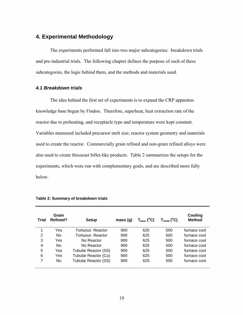
The experiments performed fall into two major subcategories: breakdown trials
and pre-industrial trials. The following chapter defines the purpose of each of these
subcategories, the logic behind them, and the methods and materials used.
4.1 Breakdown trials
The idea behind the first set of experiments is to expand the CRP apparatus
knowledge base begun by Findon. Therefore, superheat, heat extraction rate of the
reactor due to preheating, and receptacle type and temperature were kept constant.
Variables measured included precursor melt size, reactor system geometry and materials
used to create the reactor. Commercially grain refined and non-grain refined alloys were
also used to create thixocast billet-like products. Table 2 summarizes the setups for the
experiments, which were run with complementary goals, and are described more fully
below.
Table 2: Summary of breakdown trials
Trial Grain
Refined? Setup mass (g) Tpour (oC) Tmold (oC) Cooling Method
1 Yes Tortuous Reactor 900 625 500 furnace cool 2 No Tortuous Reactor 900 625 500 furnace cool 3 Yes No Reactor 900 625 500 furnace cool 4 No No Reactor 900 625 500 furnace cool 5 Yes Tubular Reactor (SS) 900 625 500 furnace cool 6 Yes Tubular Reactor (Cu) 900 625 500 furnace cool 7 No Tubular Reactor (SS) 900 625 500 furnace cool

20
Figure 2: CRP apparatus setups for breakdown trials: (A) one melt, torturous reactor, (B) one melt, no reactor, and (C) one melt, tubular reactor.
4.1.1 CRP Apparatus: One melt, tortuous reactor
The current CRP apparatus was setup as shown in figure 2(A) for this trial. About
900 grams of material was placed in a ceramic holding crucible with a ceramic “stopper”
and was melted in a resistance furnace. Material was either commercially grain refined
A356 or specially made A356 with no grain refiner (Table 3). The melting furnace was
preset to 690oC and covered with fibrofrax insulation as it heated. A bent 1” diameter
stainless steel transport tube defined the flow path from the melting crucible into a copper
tortuous path reactor. A diagram of the reactor’s interior is shown in figure 3. A low
carbon steel crucible was used as the slurry receptacle. It was placed in another
resistance furnace set below the reactor exit. The furnace was covered with insulation
A B C

21
and set to a 500oC preheat temperature. Boronitride coating was applied previously to all
surfaces in the flow path (melting crucible, stopper, transport tube, reactor, and receiving
crucible) and was reapplied as necessary. Type K thermocouples were used to measure
the temperature of the holding crucible and receiving crucible. Temperature data was
recorded with a NI-DAQ® data acquisition system and DasyLab® software.
Table 3: Alloy compositions used in the breakdown trials
Alloy Si Fe Mg Ti AlTi-grain refined A356 6.96 0.054 0.352 0.230 bal.non-grain refined A356 6.96 0.044 0.380 0.011 bal.
wt% element
Figure 3: Diagram of tortuous reactor interior
Once the melt in the holding crucible reached 650oC, the melting furnace was
turned off, and the insulation on top of the melting crucible was partially removed. The
melt was allowed to cool to the pouring temperature of 625oC at about 0.1oC/s. This
pouring temperature corresponds to about 9oC of superheat for the alloys considered. As

22
the melt approached the pouring temperature, the insulation on the top of the receiving
crucible was removed, and the furnace was checked to make sure it was rolled into place
underneath the reactor exit hole. At the pouring temperature, the operator flipped a
switch enabling a solenoid to withdraw the stopper from the bottom of the melting
crucible. The melt flowed through the transport tube and reactor into the receiving
crucible, where the melt was allowed to solidify within the furnace (furnace cooling).
Once the casting was relatively cool (about 100oC), the receiving crucible was removed
from the furnace, and the casting was ejected. Metallographic samples were prepared in
accordance with section 4.1.4 below.
For each experiment, the null hypothesis was utilized: the CRP would be able to
promote a globular microstructure with this setup based on Findon’s results with one tube
and a smaller initial quantity of melt.
4.1.2 CRP Apparatus: One melt, no reactor
In this trial, the tortuous reactor system was removed, as depicted in figure 2(B)
above. Following the procedure of section 4.1.1, a 900 gram charge was melted within
the holding crucible and the low carbon steel receiving crucible was preheated to 500oC.
The furnace was shut off and the melt was cooled to the pouring temperature in
accordance with section 4.1.1.
Before turning on any furnaces, a steel plate covered with fibrofrax insulation was
placed upon two aluminum cross bars below the holding crucible exit. The cross bars
normally support the copper reactor. As the melt approached the pouring temperature,
the receiving crucible was removed from the furnace with steel tongs and placed on the
insulation atop the steel plate below the holding crucible exit. In this manner, the

23
receiving crucible could be supported and would not lose excess heat to the steel plate or
aluminum struts.
When the stopper was removed from the holding crucible, the melt poured out the
bottom through the air into the receiving crucible below. After pouring, the operator
grabbed the crucible with tongs and placed it back in the furnace. The sample was
furnace cooled, removed, and microstructurally examined in the same way as described
in section 4.1.1.
Again, for this experiment, the null hypothesis is used: it is assumed that without
the reactor system, there would not be enough nucleation and forced convection to
promote a globular slurry. In essence, ambient air was the reactor.
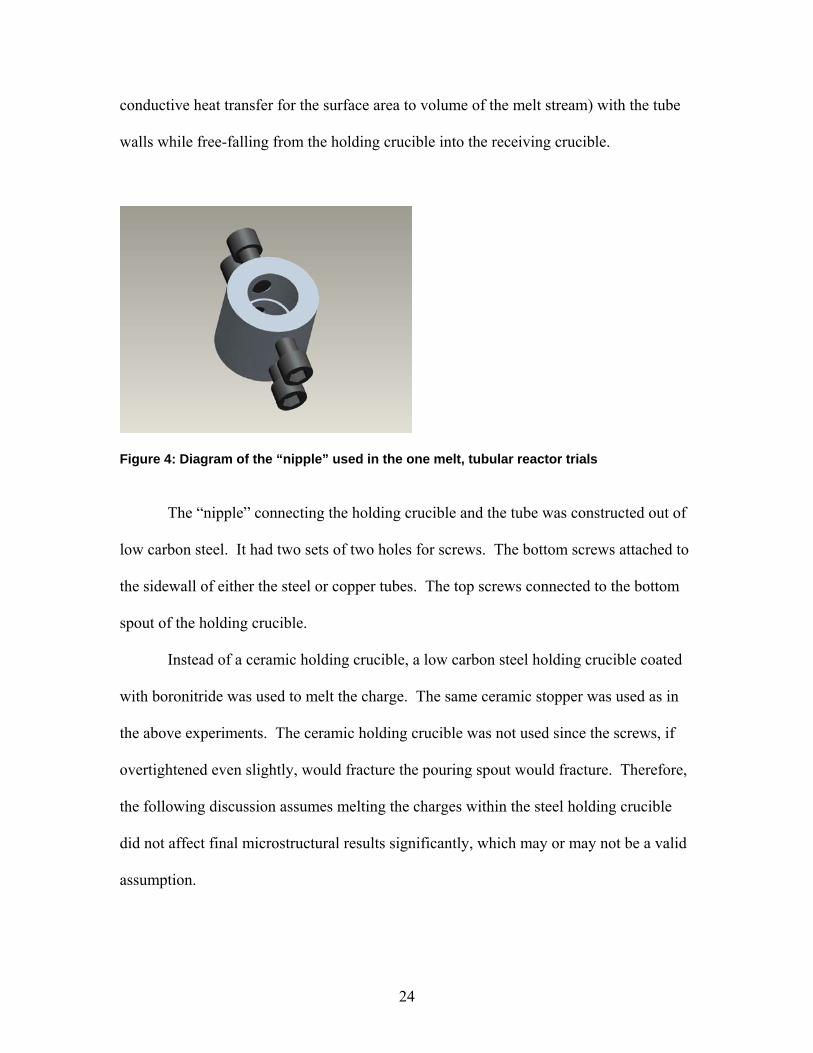
4.1.3 CRP Apparatus: One melt, tubular reactors
The CRP apparatus setup for this experiment is shown in figure 2(C). A new
reactor system was designed to connect directly to the pouring spout of the holding
crucible. A 26.5” long, 0.5” outer diameter thin-walled tube made out of either stainless
steel or copper was connected by a “nipple” (figure 4) to a low carbon steel holding
crucible. The particulars of this design are laid out below.
Copper and stainless steel were picked for their differing heat extraction material
properties. The length of the tube was chosen so that it would eliminate melt stream
contact with the surrounding air from holding crucible exit to receiving crucible top. The
outer diameter was specified so that the inner diameters of the tubes would be as flush as
possible to the inner diameter of the pouring spout of the holding crucible. In this way, it
was hoped that the melt would be in maximum contact (and thus a maximum amount of
24
conductive heat transfer for the surface area to volume of the melt stream) with the tube
walls while free-falling from the holding crucible into the receiving crucible.
Figure 4: Diagram of the “nipple” used in the one melt, tubular reactor trials
The “nipple” connecting the holding crucible and the tube was constructed out of
low carbon steel. It had two sets of two holes for screws. The bottom screws attached to
the sidewall of either the steel or copper tubes. The top screws connected to the bottom
spout of the holding crucible.
Instead of a ceramic holding crucible, a low carbon steel holding crucible coated
with boronitride was used to melt the charge. The same ceramic stopper was used as in
the above experiments. The ceramic holding crucible was not used since the screws, if
overtightened even slightly, would fracture the pouring spout would fracture. Therefore,
the following discussion assumes melting the charges within the steel holding crucible
did not affect final microstructural results significantly, which may or may not be a valid
assumption.

25
Before heating, the steel receiving crucible was placed in its furnace and was
centered underneath the tube exit. The melt was prepared to its pouring temperature and
the receiving crucible was preheated in the same way as section 4.1.1. Again, when the
pouring temperature of the melt was reached, the stopper was removed from the holding
crucible pouring spout, and the melt ran through the tube into the receiving crucible.
After pouring, the casting was cooled, removed, and examined as described above in
section 4.1.1.
It was hypothesized that this new reactor system would provide a globular slurry.
However, since the melt basically freefalls through the tube, much like how the melt
freefalls through air in section 4.1.2, it was thought that the heat extraction capability of
the tube would be the primary reason for globular slurry formation.
4.1.4 Sample Preparation and Microstructural Analysis
Samples were prepared in two fashions in order to characterize macrostructure
and microstructure. For macrostructures, samples were sectioned to show the center of
the casting from top to bottom. Coarse grit SiC paper was used to grind the samples,
which were subsequently etched for 1 minute with 10% w/v KOH aqueous solution at 60-
70ºC. For microstructures, samples were taken from the location (outer radius, center
height) shown in figure 5 below. Samples were mounted in bakelite, and ground with
successively finer SiC papers to 4000 grit. Then, they were pre-polished with 1.0 µm and
0.3 µm alumina paste on a Struers MDChem pad. Final polish was performed with
colloidal SiC on a Struers MDChem pad. Samples were subsequently etched with
Keller’s Reagent.

26
Microstructures of castings were photographed and analyzed with one of two
microscope systems: (1) a Nikon Epiphot microscope connected to an UNIX terminal
running Context Vision contextual image analysis software, and (2) a Nikon Epiphot-200
microscope equipped with a Nikon DXM1200F 0.7x digital camera and Nikon ACT-1
imaging software. Scale bars indicating the magnification of each photograph are shown
in the figures below. Images were enhanced for contrast and brightness as necessary.
Figure 5: Diagram of location within casting from where microstructure derived
4.2 Pre-industrial trials
Based on the understanding achieved from the studies above and past trials, two new
reactor designs (figures 6 - 7) were created. These designs are described as a split-
channel plate and a sloped steel tube.
The split-channel plate is block of low carbon steel with two parallel channels
which converge partway down the plate. The fundamental idea of the design is similar to
the two-melt tortuous reactor CRP apparatus setup used by Findon. It attempts to provide

27
copious nucleation within two separate flow streams which then mix upon one another,
whereby nuclei are distributed throughout the converged melt stream.
The sloped steel tube is basically a fifteen inch long, one inch outer diameter
stainless steel tube. At one end of the tube, a 1½ inch long cutout of the top of the tube is
made to allow the melt to enter the tube. The interior of the tube was coated with
boronitride. This reactor was modeled after the thin tubes used in the breakdown study
above.
Figure 6: Split channel plate reactor
Figure 7: Sloped steel tube reactor
The reactors were mounted on a cart so that they could be wheeled around the
shop floor. The cart can angle the reactor over a wide range. A steel pouring cup, shown
in figure 6 was attached to the top of the reactor. The split-channel reactor had an
ellipsoidal pouring cup, while the sloped steel tube had a circular pouring cup.
Conceptualized to be easily retrofitted to a high pressure die casting machine, the designs
were tested as shown in table 4, and as more fully described below.

28
Table 4: Summary of pre-industrial trials conditions
Trial Tpour Reactor? Tquench Tmold fce Alloy Mold A 720 NONE 580 300 GR A356 Ceramic
B.1 720 Split-Channel Plate 580 300 GR A356 Ceramic B.2 680 Split-Channel Plate 580 300 GR A356 Steel B.3 650 Split-Channel Plate 580 300 GR A356 Steel B.4 630 Split-Channel Plate 580 300 GR A356 Steel C.1 720 Sloped Steel Tube 580 300 NGR Alloy Ceramic C.2 680 Sloped Steel Tube 580 300 NGR Alloy Steel C.3 650 Sloped Steel Tube 580 300 NGR Alloy Steel C.4 630 Sloped Steel Tube 580 300 NGR Alloy Steel
4.2.1 Split Channel Plate
In this set of experiments, an Inductotherm® induction furnace was used to melt
about 40 lbs of material. The alloy used was a commercially provided Ti-grain refined
alloy whose composition is shown in table 5. The reactor and receiving crucibles were
preheated in a box furnace at 300oC. Receiving crucibles were made of either low carbon
steel or clay-graphite (ceramic) materials. Table 4 shows which crucible was used with
which trial. Before each pour, the surface of the melt was scraped clean of all dross;
furthermore, receiving crucibles were taken out of the box furnace and were placed on a
jack at the base of the reactor exit. Then, a large steel ladle coated with boronitride
withdrew a volume of melt. The melt temperature was recorded with a K-type
thermocouple. When the melt reached the respective pouring temperature for the four
trials (720oC, 680oC, 650oC or 630oC), the operator poured the melt from the ladle into
the reactor pouring cup. The melt flowed through the cup onto the split channel plate.
After traversing the plate, the melt cascaded into the receiving crucible.

29
Utilizing a similar technique one additional pour was made. In this case, the melt
was poured directly (i.e., no reactor) into a receiving crucible once the melt temperature
within the ladle reached 720oC. Therefore, the effect of the reactor could be compared to
this control sample (trial A).
In all cases, after pouring, the temperature of the solidifying melt was monitored.
When the temperature recorded reached 580 oC, corresponding to about 50% fraction
solid, each casting was quenched to preserve the microstructure exhibited at that
temperature. Resultant castings were removed, sectioned, and metallographically
prepared for microstructural analysis as described in section 4.1.4 above.
Since the fundamental concept behind the split-channel plate is similar to the CRP
apparatus, it is hypothesized that the novel reactor will be able to provide a globular
slurry for all temperatures, as long as it extracts enough heat to allow the melt to reach its
liquidus. Additionally, the grain sizes should increase with increasing superheat.
4.2.2 Sloped Steel Tube
The experimental procedure for the sloped steel tube trials was similar to that in
section 4.2.1. One difference was that no pour was made at 720oC without a reactor. The
alloy used was different, which must be explained in detail.
The experimental plan called for the use of the same specially prepared non-grain
refined A356 type alloy used in the breakdown trials (Table 3). However, after the trials
were run, it was found that the alloy composition was not what was specified. The
composition realized is shown below in Table 5. It is high in copper, magnesium, zinc,
and manganese, and relatively low in silicon. Therefore, the microstructures will not be
directly comparable to the others in this study. However, even if the alloy used in this
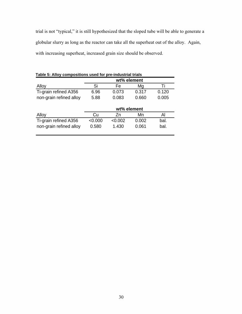
30
trial is not “typical,” it is still hypothesized that the sloped tube will be able to generate a
globular slurry as long as the reactor can take all the superheat out of the alloy. Again,
with increasing superheat, increased grain size should be observed.
Table 5: Alloy compositions used for pre-industrial trials
Alloy Si Fe Mg TiTi-grain refined A356 6.96 0.073 0.317 0.120non-grain refined alloy 5.88 0.083 0.660 0.005
Alloy Cu Zn Mn AlTi-grain refined A356 <0.000 <0.002 0.002 bal.non-grain refined alloy 0.580 1.430 0.061 bal.
wt% element
wt% element
31
5. Results & Discussion
5.1 Breakdown Study
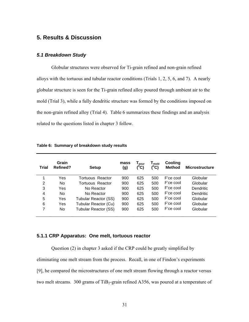
Globular structures were observed for Ti-grain refined and non-grain refined
alloys with the tortuous and tubular reactor conditions (Trials 1, 2, 5, 6, and 7). A nearly
globular structure is seen for the Ti-grain refined alloy poured through ambient air to the
mold (Trial 3), while a fully dendritic structure was formed by the conditions imposed on
the non-grain refined alloy (Trial 4). Table 6 summarizes these findings and an analysis
related to the questions listed in chapter 3 follow.
Table 6: Summary of breakdown study results
Trial Grain
Refined? Setup mass
(g) Tpour (oC)
Tmold (oC)
Cooling Method Microstructure
1 Yes Tortuous Reactor 900 625 500 F’ce cool Globular 2 No Tortuous Reactor 900 625 500 F’ce cool Globular 3 Yes No Reactor 900 625 500 F’ce cool Dendritic 4 No No Reactor 900 625 500 F’ce cool Dendritic 5 Yes Tubular Reactor (SS) 900 625 500 F’ce cool Globular 6 Yes Tubular Reactor (Cu) 900 625 500 F’ce cool Globular 7 No Tubular Reactor (SS) 900 625 500 F’ce cool Globular
5.1.1 CRP Apparatus: One melt, tortuous reactor
Question (2) in chapter 3 asked if the CRP could be greatly simplified by
eliminating one melt stream from the process. Recall, in one of Findon’s experiments
[9], he compared the microstructures of one melt stream flowing through a reactor versus
two melt streams. 300 grams of TiB2-grain refined A356, was poured at a temperature of

32
625 ºC through the tortuous reactor system into a graphite-clay crucible heated to 500 ºC.
He found that the resultant slurry provided a globular structure only slightly larger in
grain size than a similar experiment mixing two melts in the tortuous reactor system. A
question arose whether the grain refinement of the alloy used was producing an effect on
the resultant microstructure. Therefore, Findon’s experiment was repeated (although
with three times as much initial melt) with titanium grain refined and non-grain refined
alloys (trials 1 & 2).
Figure 8: Trial 1 – grain refined alloy, tortuous reactor
Figure 9: Trial 2 – non-grain refined alloy, tortuous reactor
The microstructures that developed from the conditions imposed are shown in
figures 8 and 9. Each microstructure is globular and highly refined as compared to
ingots. Recall, the structures are thixocast structures, not rheocast structures. Not much
difference between the two images is apparent to the naked eye.
33
A number of conclusions can be drawn from these results. First, the imposed
thermal profile and convection level provided by flowing one melt through the reactor is
sufficient to result in globular SSM structures. The CRP can therefore be simplified
greatly by excluding the second melting furnace. A two furnace design is only needed if
there is a special need for two melts. One circumstance would be to utilize the benefits of
mixing two compositionally different melts, as in Controlled Diffusion Solidification.
[24] Another reason would be a need to mix two melts of different temperatures;
however, it is not clear what benefits would be achieved from this practice.
Second, due to the similar structures seen for both alloy types, grain refinement
appears to be not a major cause of the microstructure produced by allowing one melt
stream to flow through the tortuous reactor system. Findon previously found that grain
refinement was not necessary for developing globular slurries with two melt streams
running through the tortuous reactor system. Mechanical properties of the castings
produced have not been determined at this time. However, since grain size is a major
determinant of mechanical properties [25], it would not seem that these properties would
be much different in castings formed from semisolid slurries of either alloy. Oxides and
porosity also greatly determine quality of castings [26], but these also have not been
measured. Therefore, the added cost of grain refiner should not be necessary when using
the CRP, unless another reason than those given above calls for it.
Third, since three times more melt was used, larger melt sizes can be processed by
the tortuous reactor than previously recorded. This affirmatively answers question (1) of
Chapter 3. However, melts larger than 900 grams can not be made safely with the current
CRP apparatus. The melting furnace and holding crucible volumes must both be

34
increased to allow more charge to be melted. Additionally, the stopper height must be
increased in tandem with any holding crucible dimensional change. Finally, the melting
furnace power must be increased. Currently it takes over one hour to melt 900 grams of
material, which is not acceptable for a commercial process.
5.1.2 CRP Apparatus: One melt, no reactor
Findon examined many variables in his work; however, he never eliminated the
full reactor system as a process variable. Therefore, the question arises: if the reactor
system is removed, and the melt pours from the bottom of the holding crucible into the
receiving crucible, will a globular slurry form? The receiving crucible temperature is
below that of the melt liquidus temperature, a possible nucleation enhancer.
Additionally, as the melt stream splashes into the receiving crucible, much forced
convection could take place which would allow nascent nuclei to distribute evenly
throughout the melt.
Two mechanisms have been proposed in the literature that would support this
theory. First, low superheat pouring, as utilized in the MX process described above,
solely pours a low superheat melt into a relatively cool mold [7, 27]. In Findon’s
experiments and the one-melt trial above, the melt contained relatively little superheat
before pouring; therefore, this is a probable mechanism. Secondly, it has been suggested
that rapid cooling of a poured melt within a mold enables globular structure formation
[28]. In many rheocasting experiments discussed in the literature, including some of
Findon’s trials, researchers quench their samples to “freeze” the microstructure present in
the two phase regime. However, if the proposed rapid cooling mechanism is true,
researchers draw the incorrect conclusions from their results. Therefore, in the
35
breakdown trials, furnace-cooled thixocast billets were deliberately made in order to
eliminate the rapid cooling (quenching) effect.
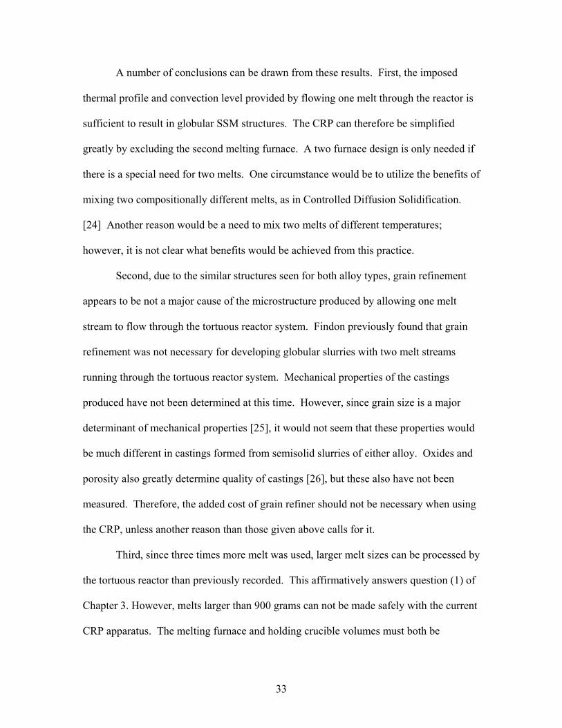
With these thoughts in mind, two billets (one titanium grain refined, the other
non-grain refined) were cast without any reactor present. Microstructures taken from
these trials are shown below. Casting 3 exhibits a mostly dendritic structure; however,
some globules are present in the eutectic pool. Casting 4 is fully dendritic. Therefore,
using the conditions applied, a globular slurry is not attained.
Figure 10: Trial 3 – grain refined alloy, no reactor
Figure 11: Trial 4 – non-grain refined alloy, no reactor
Low superheat pouring cannot be a major mechanism in the CRP process. Findon
has shown increased superheat leads to increased grain size and decreased globularity.
However, a CRP-poured low superheat melt cannot form a globular slurry without the
help of a reactor system.
Additionally, in regards to the CRP, the rapid quenching mechanism is refuted.
The samples exhibiting globular microstructures in Findon’s experiments were cooled

36
more quickly (quenched or air cooled) than the furnace cooled samples above. While
true that the slow cooling rate used in the non-reactor system samples above did not
provide semisolid structures, the tortuous reactor system samples did exhibit globular
structures. These castings exhibited similar cooling rates to the non-reactor trial.
Therefore, the tortuous reactor system used in trials 1 and 2 can be said to play a
meaningful part in causing formation of semisolid microstructures. However, it does not
imply the conclusion that the design is the optimal and most simple design needed for the
process to work.
5.1.3 CRP Apparatus: One melt, tubular reactor
The next set of experiments were performed to analyze the effect of flow path
geometry on the microstructure produced, in order to determine the amount of forced
convection needed within the reactor system (Question (3) of Chapter 3). In the tortuous
reactor used in trials 1 and 2, deceleration of the melt stream flow takes place at each of
the numerous “corners” of the flow path. Intense forced convection coupled with
conductive heat transfer occurs at these points. In this trial, the reactor was greatly
simplified. A tubular reactor (trials 5, 6, and 7) made of either stainless steel or copper
guided the fluid into the receiving crucible.
This simplified reactor minimizes the amount of forced convection present in the
reactor system. The path laid out by the new reactor was straight up and down, unlike the
numerous twists and turns of the tortuous reactor system. In this way, the melt stream
acceleration should approach free fall conditions, much like the non-reactor trial
described above. The tubular reactor melt stream should only experience small drag

37
forces due to the tube walls, just like as in a sprue system. Therefore, without the
possibility sudden melt deceleration, a large amount of mixing should not take place.
Additionally, the simplified reactor increases the heat extraction capability almost
to a maximum. In the tortuous reactor system, the melt stream and reactor system
surfaces are not always fully in contact. This is because the reactor channel diameter is
wider than the holding crucible pouring nozzle exit. Because of this, the melt stream will
always be slightly in contact with air. As shown in the previous non-reactor trial, air
cannot extract enough heat from the melt stream to promote nucleation. With the tubular
reactor, the channel diameter is nearly the same as the holding crucible pouring nozzle
exit. Therefore, the melt stream surface should be in constant contact with the conductive
tube walls.
Therefore, using this simple design, heat extraction should dominate over forced
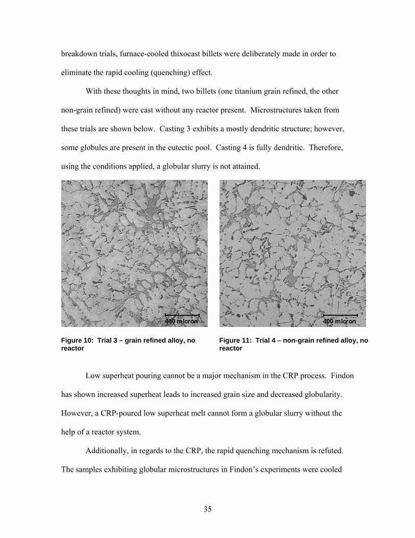
convection, and their relative effects can be analyzed. Microstructure analyses show that
both the tubular reactor trials – stainless steel (trials 5 and 6) and copper (trial 7) –
provided sufficient heat extraction and forced convection to form similar globular
microstructures as seen in the tortuous reactor system castings (trials 1 and 2).
The results indicate that increasing the rate of heat transfer from a flowing melt
stream can enhance nucleation, and only a slight amount of forced convection is needed
to redistribute nuclei, and thus to lead to the formation of globular semi-solid structures.
Tortuous forced convection within a static reactor is not required. Therefore, new, less
complicated reactors can be designed.
38
Figure 12: Trial 5 – grain refined alloy, stainless steel tubular reactor
Figure 13: Trial 6 – grain refined alloy, copper tubular reactor
Figure 14: Trial 7 – non-grain refined alloy, stainless steel tubular reactor
Figure 15: Trial 6 – grain refined alloy, copper tubular reactor – remnant material stuck within tube
In trial 6, some remnant material stuck at the bottom of the copper reactor. This
material was sectioned and polished to determine whether nucleation took place in the
reactor. As can be seen from figure 15, a highly globular structure formed. Looking at

39
the scale bar, the size of each grain is about ½ the size as those in castings 5, 6, and 7.
Since the remnant material stuck in the room temperature copper tube would solidify
faster than the casting in the hot steel receiving crucible, a large amount of grain growth
and coarsening takes place in the receiving crucible. However, the grains retain their
spheroidicity.
5.2 Pre-industrial trials
Utilizing the knowledge gleaned from the breakdown trials, pre-industrial trials
were performed with two novel reactors. Globular structures were observed for Ti-grain
refined and non-grain refined alloys for all but one of the split-channel plate and sloped-
steel tube reactor conditions. (Table 7) The only dendritic structures observed were
developed from the non-reactor trial and the 720ºC pouring temperature/sloped-steel tube
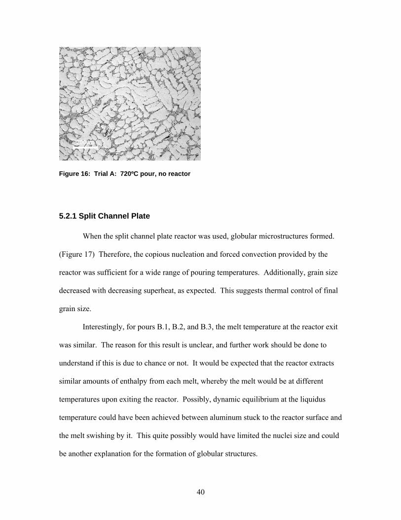
trial. The non-reactor trial A microstructure, as exhibited in figure 16, shows that a
reactor is again needed, and normal pouring and rapid quenching is not sufficient to form
SSM structures. Table 7 summarizes the overall findings, and an analysis of the two
reactor’s results follows.
Table 7: Summary of pre-industrial trial results (SCP – Split-Channel Plate, SST – Sloped Steel Tube)
Trial Tpour Reactor? Tquench Tmold fce Alloy Mold Texit Microstructure A 720 NONE 580 300 GR A356 Ceramic N/A Dendritic
B.1 720 SCP 580 300 GR A356 Ceramic 612 Globular B.2 680 SCP 580 300 GR A356 Steel 610 Globular B.3 650 SCP 580 300 GR A356 Steel 610 Globular B.4 630 SCP 580 300 GR A356 Steel 594 Globular C.1 720 SST 580 300 NGR Alloy Ceramic 630 Dendritic C.2 680 SST 580 300 NGR Alloy Steel 614 Globular C.3 650 SST 580 300 NGR Alloy Steel 614 Globular C.4 630 SST 580 300 NGR Alloy Steel 610 Globular
40
Figure 16: Trial A: 720ºC pour, no reactor
5.2.1 Split Channel Plate
When the split channel plate reactor was used, globular microstructures formed.
(Figure 17) Therefore, the copious nucleation and forced convection provided by the
reactor was sufficient for a wide range of pouring temperatures. Additionally, grain size
decreased with decreasing superheat, as expected. This suggests thermal control of final
grain size.
Interestingly, for pours B.1, B.2, and B.3, the melt temperature at the reactor exit
was similar. The reason for this result is unclear, and further work should be done to
understand if this is due to chance or not. It would be expected that the reactor extracts
similar amounts of enthalpy from each melt, whereby the melt would be at different
temperatures upon exiting the reactor. Possibly, dynamic equilibrium at the liquidus
temperature could have been achieved between aluminum stuck to the reactor surface and
the melt swishing by it. This quite possibly would have limited the nuclei size and could
be another explanation for the formation of globular structures.

41
Figure 17: Microstructures obtained from trial B (split channel plate reactor) – B.1: 720ºC pour, B.2: 680ºC pour, B.3: 650ºC pour, B.4: 630ºC pour.
One drawback of the reactor is that as pouring temperatures decreased, increased
melt amounts would freeze to the reactor, forming increasing larger “sprues.” This
phenomenon decreased the yield of the pours. A suggestion would be to coat the reactor
with boronitride and repeat the experiments to see if sticking is decreased.
Another suggestion would be to include some sort of automatic pouring system to
control final casting size. A hand-held ladle was used, and could only pour a limited
amount of melt into the reactor. Thus, the final casting mass varied over a wide range.
42
Finally, this reactor should be retrofitted to a current die casting machine setup to
see if the slurry formed has the rheology desired. The experimental setup did not allow
measurement of the thixotropic properties of the slurry. Since the ACRC does not have a
die casting machine in its lab, the experimental plan necessarily called for permanent
mold castings. This, of course, is not directly comparable to the intended end-use of the
reactor.
5.2.2 Sloped Steel Tube
For the three lowest superheat melts poured, globular microstructures were
observed. However, for the 720ºC pouring temperature, a fully dendritic structure
developed. As can be seen in Table 7 above, for this condition, the temperature of the
melt at the reactor exit was 16 to 20ºC higher than the other three pours. If the liquidus
temperature of the off-spec alloy was lower than the reactor exit temperature, then this
finding shows once again that the melt must begin solidifying within the reactor in order
for a globular structure to form. Another possible reason why not enough enthalpy
extraction took place with the sloped steel tube is that possibly less melt surface area was
in contact with the tube than on the split channel plate. The split channel plate was also
thicker, allowing more heat to be stored in the reactor without raising its temperature,
unlike the thin walled steel tube. Quite possibly, the optimum reactor would be a water-
cooled thick-walled tube of similar diameter to the pouring cup. Or, even better, it would
be tapered like a parabolic sprue to allow maximum melt contact and velocity control and
a minimum of aspiration [29].

43
Figure 18: Microstructures obtained from trial C (sloped steel tube reactor) – C.1: 720ºC pour, C.2: 680ºC pour, C.3: 650ºC pour, C.4: 630ºC pour.
The “sprues” left over in the sloped steel tube were much smaller than in the split
channel plate trials, and therefore, casting yield increased. This result possibly is due to
the fact that the tube was coated with boronitride. However, casting size varied due to
uncontrolled mass in the pouring ladle. Again, pours should be made allowing for a
consistent casting size for each level of superheat to see if any size effects come into
play.
Finally, even though the alloy was not an A356-type alloy, globular structures still
formed, and grain size decreased with decreasing superheat as expected.
44
6. Conclusions
In chapter 3, four questions were asked. The following answers those questions
from the results obtained above.
(1) Can the CRP convert larger volume melts?
In the CRP breakdown studies, three times more melt (900 grams vs. 300 grams)
were converted into globular slurry than previously reported. A larger and more
powerful melting system must be added to the CRP in order for larger melts to be made
safely.
(2) Can the CRP be simplified by flowing one melt instead of two melts?
The mixing action of two melt streams inside a reactor was found not to be
required to produce globular slurry. One melt stream flowing through the reactor was
sufficient. Therefore, previous CRP designs with two crucibles can be greatly simplified
by eliminating one of the crucibles. This is a major advantage for commercial
applications.
(3) How critical is heat extraction vs. forced convection?
Both forced convection and heat extraction rate are critical parameters needed to
be controlled in order to produce high quality SSM globular structures via the rheocasting
route. However, heat extraction via a reactor seems to have a larger effect. Globular
structures cannot be obtained by pouring low superheat melt stream into a relatively cool
mold. A reactor is needed to control the nucleation and the distribution of the nuclei in
the melt as it is flowing into the receiving crucible.
Supporting this fact, a new tubular reactor to fit into the CRP apparatus was
designed. The tubular design, which is much simpler than the previously designed

45
tortuous reactor, is effective in extracting heat from the flowing melt; however, the
tubular reactor does not promote as large amounts of forced convection as the tortuous
reactor. Since globular structures were achieved with the tubular reactor system, the
primary purpose for a reactor design should be to extract heat from a flowing melt
stream. Forced convection should be a secondary consideration.
(4) What is the optimal design for the reactor?
Three new reactors were created in this study. The tubular reactor attempts to
minimize forced convection and maximize heat extraction. The split channel plate and
sloped steel tube attempt to provide heat extraction and forced convection while being
easily retrofittable to current die casting cells. The split channel plate provides globular
slurry over a wide range of superheats, while the sloped steel tube shows more limited
utility. However, both provide high nucleation within the melt and forced convection of
the melt. Based on the successful results, beta trials using the two new reactors within
die casting machines have been arranged.
46
7. References
1. UBE Industries Ltd., Method and apparatus for shaping semisolid materials, in
European Patent EP 0 745 694 A1. 1996. p. 117.
2. Yurko, J.A., R.A. Martinez, and M.C. Flemings, SSRTM: The Spheroidal Growth
Route to Semi-Solid Forming, in 8th International Conference on Semi-Solid
Processing of Alloys and Composites. 2004: Limassol, Cyprus.
3. Jorstad, J.L., SSM Processes - An Overview, in 8th International Conference on
Semi-Solid Processing of Alloys and Composites. 2004: Limassol, Cyprus.
4. Spencer, D.P., R. Mehrabian, and M.C. Flemings, Rheological Behavior of Sn-15
Pct Pb in the Crystallization Range. Metallurgical Transactions, 1972. 3: p. 1925-
1932.
5. Udvardy, S., Processing Economics, Markets, & Future Challenges, in Science
and Technology of Semi-Solid Metal Processing, A. de Figueredo, Editor. 2001,
NADCA: Rosemont, IL.
6. Alexandrou, A., Rheology & Numerical Simulations of Flow of Semi-Solid
Suspensions, in Science and Technology of Semi-Solid Processing, A. de
Figueredo, Editor. 2001, NADCA: Rosemont, IL.
7. de Figueredo, A. and D. Apelian, Processing Routes, in Science and Technology
of Semi-Solid Metal Processing, A. de Figueredo, Editor. 2001, NADCA:
Rosemont, IL.
8. Flemings, M.C., Behavior of Metal Alloys in the Semisolid State. Metallurgical
Transactions A, 1991. 22A: p. 957-981.
9. Findon, M.M., Semi-Solid Slurry Formation via Liquid Metal Mixing, in
Materials Science and Engineering. 2003, Worcester Polytechnic Institute:
Worcester, MA. p. 98.
10. Pan, Q.Y., M. Findon, and D. Apelian, The Continuous Rheoconversion Process
(CRP): A Novel SSM Approach, in 8th International Conference on Semi-Solid
Processing of Alloys and Composites. 2004: Limassol, Cyprus.
11. Rosen, S.L., Fundamental Principles of Polymeric Materials. Second ed. 1993:
John Wiley & Sons, Inc. 420.
47
12. de Figueredo, A., ed. Science and Technology of Semi-Solid Metal Processing.
2001, North American Die Casting Association: Rosemont, IL.
13. Kirkwood, D.H., Semisolid metal processing. International Materials Reviews,
1994. 39(5): p. 173-189.
14. Jackson, K.A., et al., On the Origin of the Equiaxed Zone in Castings.
Transactions of the Metallurgical Society of AIME, 1966. 236: p. 149-158.
15. Molenaar, J.M.M., F.W.H.C. Salemans, and L. Katgerman, The structure of
stircast Al-6Cu. Journal of Materials Science, 1985. 20: p. 4335-4344.
16. Molenaar, J.M.M., et al., On the formation of the stircast structure. Journal of
Materials Science, 1986. 21: p. 389-394.
17. Doherty, R.D., H.-I. Lee, and E.A. Feest, Microstructure of Stir-cast Metals.
Materials Science and Engineering, 1984. 65: p. 181-189.
18. Jorstad, J.L., Practical Considerations of Processing, in Science and Technology
of Semi-Solid Processing, A. de Figueredo, Editor. 2001, NADCA: Rosemont, IL.
19. Doutre, D., J. Langlais, and S. Roy, The SEED Process for Semi-Solid Forming,
in 8th International Conference on Semi-Solid Processing of Alloys and
Composites. 2004: Limassol, Cyprus.
20. DOE Report number DE-FC07-98ID13618.
21. Flemings, M.C. Semi-Solid Processing - The Rheocasting Story". in Test Tube to
Factory Floor: Implementing Technical Innovations (MPI Spring Symposium,
May 22, 2002). 2003. Worcester Polytechnic Institute, Worcester, MA: Metal
Processing Institute.
22. Martinez, R.A., et al., NADCA Transactions, 2001: p. 47 - 54.
23. DasGupta, R., Q.Y. Pan, and W.J. Bernard III, Unpublished Work. 2004.
24. Shankar, S., et al., CDS: Controlled Diffusion Solidification: a novel casting
approach, in 8th International Conference on Semi-Solid Processing of Alloys
and Composites. 2004: Limassol, Cyprus.
25. Reed-Hill, R.E. and R. Abbaschian, Physical Metallurgy Principles. Third ed.
1994, Boston, MA: PWS Publishing Company. 926.
26. Campbell, J., Castings. Second ed. 2003, Oxford: Butterworth Heinemann. 335.
48
27. Wang, H., et al., Semisolid Casting of AlSi7Mg0.35 Alloy Produced by Low-
Temperature Pouring. Materials Science Forum, 2002. 396-402: p. 143-148.
28. Browne, D.J., M.J. Hussey, and A.J. Carr, Towards Optimization of the Direct
Thermal Method of Rheocasting, in 8th International Conference on Semi-Solid
Processing of Alloys and Composites. 2004: Limassol, Cyprus.
29. Flemings, M.C., Solidification Processing. 1974: McGraw-Hill. 355.