Embed Size (px)
Citation preview
The Collapse Strength o f S tee 1 Columns
...
Interim Report No. 1
C1aSSIFIC~TION OF COLmv~ PROBLEMS
:By
Lynn S. Beedle
Sponsor
Sandia Corporation, P. O. No. W-906
Fri tz Engineering Labora toryDepartment of Civil Engineering and Mechanics
:Beth1ehem,Penna.
December 8, 1951
Fritz Laboratory Report No. 226.2

226.2 12/8/51 -1-
C 1 ass i f i cat ion of C'ol u m n Problems
I. I N T ROD U C T ION
.ils indicated in the proposal for this investigation {l),
the first step in the study of the collapse strength of stenl col-
umns was to make a classification of the problems and influencing
factors in order to provide a system for arranging eXisting data
on the subject. ,11 tentative classifi cation was suggested in the
proposal.
The purpose of this interim report is to present an agreed-
upon chart with a description of the type of material to be considered
under each heading. This has resulted from conferences between the
writer and Dr. Bruce Johnston. Those who are interested in this
program may Wish to make suggestions regarding arrangement ·or em-
phasis, remembering that the objective of the project is:
(a) to evaluate what is now known regardin~ the
ultimate strength of steel columns, including sum-
mary of tests, and on that basis,
(b) to develop methods of predicting the collapse
strength of columns.
(1) Proposal, "'!he Colla.pse Strength of Steel Structures It, LynnS. BeAdle, Lehigh University, File R-6.1, 25 June 1951.

226.2 12/8/51 -2-
The study is' to emphasize columns of the type used in industrial
and tier bUildings. The behavior of columns beyond the elastic limit
is of primary importance.
Other classifications of the column problem have been
presented by Salmon, Bleich, Jakkula & Stephenson, and in several
ColQmn Research Council reports. These are referred to whereap
propriate.
The next step to follow the development of the chart is
the ticketing of references in such a manner that all the reports
and abstracts concerning columns collected in the primary survey
by Dr. Johnston may be arranged under the appropriate headings of
the chart. Consideration has been given to a "keysorting" system.
There may be insufficient abstract cards to justify this system•
.oI.bstract cards are to be furnished by Dr. Bruce Johnston.

226.2 12/8/51.
I I. C H .~ R T'"
(I) MODE OF F.~ILURE (elastic and inelastic buckling)
1. Bonding2. Bending and Torsi on3. Bendin~ and Local Buckling"''''4. Bending, Torsion, and Local Buckling
(I ~ INFLUENCING FA.CTORS
A. Type of Member
1. Cross-sectional form (prismatic members)2. Slenderness ratio3. Longitudinal variation in cross-section4. Initial eccentricities and initial cur
vature5. .Q.cti on of spli ces6. Size of cross-section
B. Type of Structure (columns in trusses and rigid frames)
C. Boundary Conditions (load and restraint)
1. Type and location of loads
a. End forces and moments (3 coordinate axes)b. Intermediate loads: lateral and longitudinal
2. End Restraints (3 coordinate axes) and supports3. Lateral Support4. Encasement5. Action of End Connections6. Column Footings
D. Mechanical Properties of Material
1. Type of Material (steel)2. Variation in Material Properties throughout Member3. Effect of Fabrication ~ocesses on Material Properties4. Residual Stress Due to Fabrication Process
E. Time Effects
1. Impact
a. Blast loading
... Description of each item is contained in Section III.
** Chapter 8 of the Monograph is to include a treatment of local instabili ty.'
12/8/51
There are certain limitations in this classification.
Fatigue, b.rittle fracture modes of failure and failure due to re-
peated loading in the plastic range are not considered •
.u though a cla.ssification of the failure of columns was
not a primary purpose of the Jakkula-Stephensonsurvey(2) their
"Table of Data" contained in the section, "Selected Column Tests
Summary" lists modes of failure as follows:
1. Local-Flange
2. General
3. Local
4. Local Buckling of Flange (Tee-shape)
5. Torsional and Local Buckling
The Bleich survey(3), also contains a clasSification of
column problems and the original outline headings· are summarized
in Appendix .4..
The first Column Research Council questionnaire survey(4)
also classified column problems, again on a sligptly differ~nt basis
and this is contained in .~ppendix B. The same scheme has been used
in the second survey(5).
•(2) Jakkula, A.A. and Stephenson, H.K., "Stenl Columns: .~ Survey
and Appraisal of Past Works", Texas ~ & mBulletin No. 91,June 1, 1947.
(3) Bleich, Friedrich, "'!he Buckling.Strength of Metal Structures",McGraW-Hill, Scheduled for 1952 publication.
(4) Lundquist, Johnston, Jones, and Tammen, lISummary of .Q.nswers to~estionnaire on Important Structural Problems Involving StabilityAgainst Buckling", Column Research Council, March 31, 1947.
(5) Beedle,. Lynn S., and Johnston, Bruce, n~e3ti..onn~:ire SUrvey on CurrentResearch" Column Research Council, Sept.l, 194~ and May 2, 1950.
12/8/51 -5-
III. S COP E u FIT EMS I N T II E C II.j\, R T
The fo11owi~g is a brief description for each item presented
in Section II.
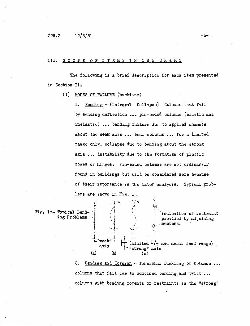
(I) MODES OF F~ILURE (buckling)
1. Bending - (Integral Collapse) Columns that fail
by bending deflection ••• pin-pnded columns (elastic anq
inelastic) ••• bending failure due to applied moments
about the weak axis ••• beam columns ••• for a limited
range only, collapse due to bending about the strong
axis ••• instability due to the formation of plastic
zones or hinges. Pin-ended columns are not ordinarily
found in buildings but will be con sidered here because
of their importance in the later analysis. Typical prob-
lems are shown in Fig. 1.
," i.J.... -J..:..."weak" I
axis
~<If)!i "Indication of restraintI provided by adj oining
\@' members.I
load range)
--1--,
- t "If'.1
I'J/-}"
I I II I, /t-j- (Limi ted L r and axial
1-- "strong" axis(c)(b)(a)
•'f1:- Typical Bend- :' I
ing problems'..lt
Fig.
Bending and Torsion - Torsional Buckling of Columns •••
columns that fail due to combined bending and tWist •••
columns with bending moments or restraints in the "strong fl
226.2 12/8/51 -6-
direction ••• the influence of non-symmetrical cross-
sections ••• open cross-sections. Fig. 2.
-'
/T'II
._. '....
".~I \~/~r? "1'
f-~-~
: (a)
Fig. 2
,--I
IL_
'-Ii I
...L,
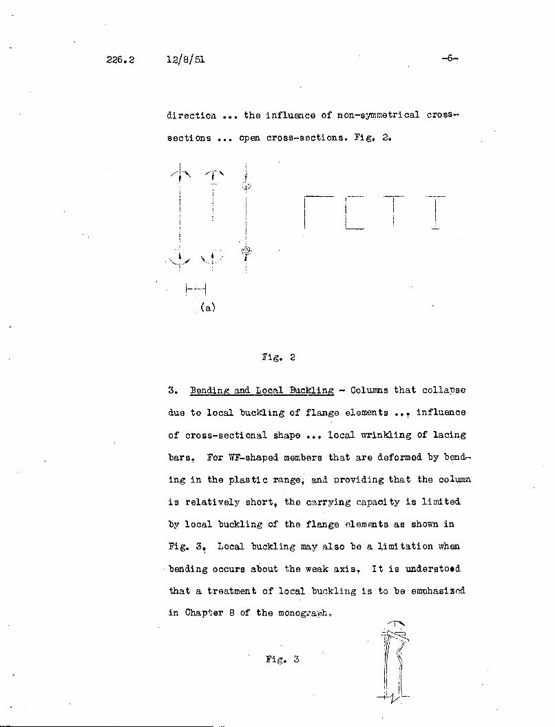
3. Bending and Local Buckling -' Columns that collapse
due to local buckling of flange elements influence
of cross-sectional shape ••• local wrinkling of lacing
bars, For WF-shaped members that are deformed by bend-
ing in the plastic range, and providing that the column
is relatively short, the carrying capaoity is limited
by local buckling of the flange elemAnts as shown in
Fig. 3~ Local buckling may also be a limitation when
bending occurs about the weak axis~ It is understold
that a treatment of local bu~kling is to be emphasizod
Fig. 3
226.2 12/8/51 -7-
4. Bending. Torsion, and Local Buckling - This is
a combination of bending, torsion and local buckling
tha t occurs, for exan p1e, when WF columns of relatively
short length are loaded in such a way that the maximum
moment is not at the column end. Bending and twisting
action oc.cur, followed in the later stages by local
buckling of the flange.
(II) INFLlTmCING F~CTORS
~. Type 0 fM e m b e r
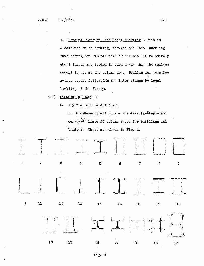
1. Cross-sectional Form - The Jakkula-Stephenson
survey(2) lists 25 column types for buildings and
bridges. These are shown in Fig. 4.
- - - =: ~--- ':. .. ----T-- !___ i "", -I - .-I
1.__..-1i II ! '-f' ; I i
II I i i
i
lI.
III i
II I ! !I ! ! i
.-1._.. I ',---1...-. _.11_. I _ i_ I.-----; I.-.~- ..... --- _.- -~. -'-
1 2 3 4 5 6 7 8 9
IIr- '-11'-'- "'-'lr-' - lil-- --r!
I I ;
,-ji._1.,
iii'I _J L_ _.111_ _cJll=-I,
'--- __..1;_.
10 11 12 13 14 15 16 17 18
II
J- ._-- -
19 20 2l
Fig. 4
22
... r
II 'I
r~'lfl-~. I~"""I_,; i-
24 25
12/8/51 -8-
It will be recognized that a large number of these are
more common for compression members in bridges. In this
projoct, ~JPes land 2, will receive predominant atten
tion. The shape may ei ther be WF or .~erican Standard I.
and althou~ only about 2fo of U.S. tonnage is of I-shape,
this section is so common in Europe that it will require
study. ~e golid T should be added to the types shown
in lig. 4 as well as the chro nel and built-up I-shape
wi th unequal flange widths.
2. Slenderness Ratio - This is a basic variable in all
column problems, the ratio of length L to radiUS of
gyration, r. Each treatmentwiil be concerned with this
influencing factor.
3. Longitudinal Variation in Cross-Section - Non-uni
formity along the member ••• variable cross-sections •••
columns With cover plates •••• longitudinal lines of
welds or rivets ••• latticed columns ••• batten plates •••
perforated cover plateD ••• non-prismatic columns ••• col
umns With off-sets ••• referring to Fig. 4, all column
types except 1, 10, lla.
4. Initial Eccentricities and Initial Curvature - ~uilt-ln
and accidental eccentricities and cUrJature ••• review
of tolorancee ••• one end twi s ted with respect to opposi tEl
end ••• ends out of square.
12/8/51 -9-
5. ~ction of Splices - Influence of rivetp.d or welded
splices on column strength.
6. Size of Cross-Section - Primarily a study of the
size or scale offect ••• comparison of tosts whose conditions
are identical with the exception of size of cross-sec-
tion. This will also involve the cross-sectional form
and residual stross.
B. T Y P e 0 f S t r u c t u res (Columns in trusses
and rigid frames)
This study is primarily that of the behavior of
tho isolated column as influenced b;r type of member,
boundary conditions, mechanical properties of the material,
and the rate of loading. Sections 9-14 of the monograph.
being prepared by Dr~ Johnston at the University of Michigan
will each deal with the complete frame of which the col
umn is a part. As indicated in·the proposal(l), progress
"notes" will be prfrpared as appropriate for inclusi on
with other sections of the monograph and will treat the
behavior of the column as part of particular structural
types. In this section would bo presented information
rela.ting ta rticularl~, to framed columns.
C. B 0 u n dar y Con d i t ion s (Load and Restraint)
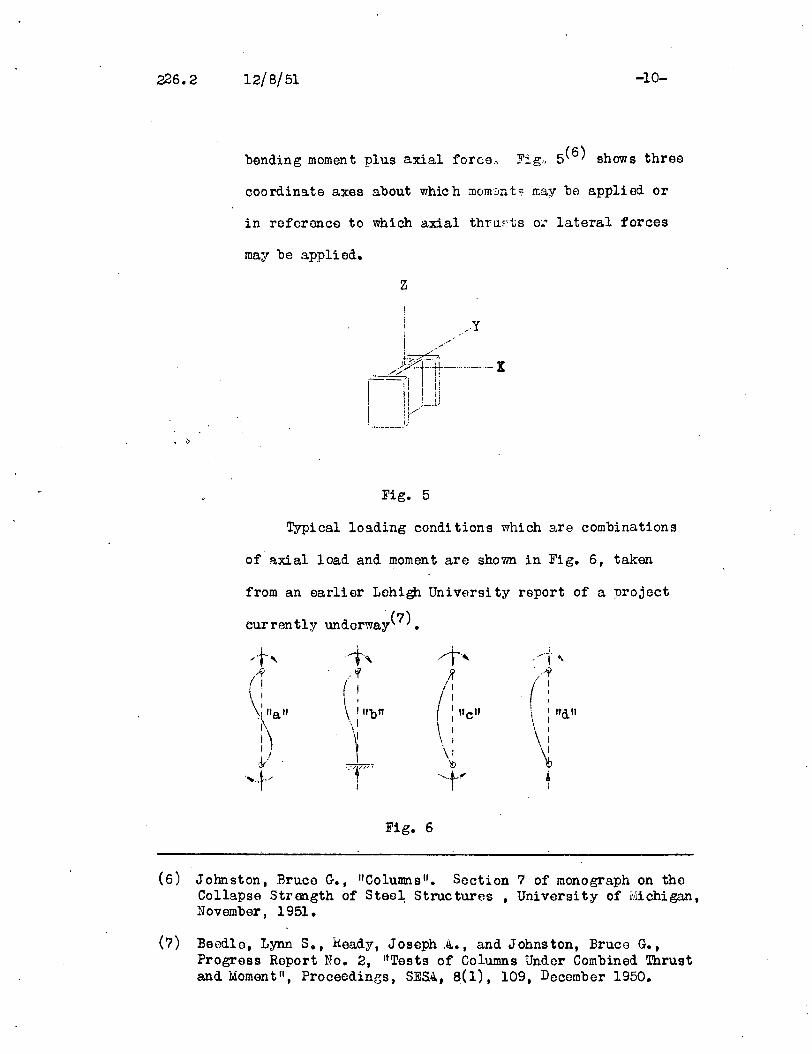
lao Typo and Location of Loads: End Forces and Moments -
~xial load ••• eccentric loqds 0". lateral loads 0 •••
226.2 12/8/51 -10-
bending moment plus axial forco., Fig" 5(6) shows three
coo rdina. te axes about whic h mom:m t s n:a.y be appli ed. or
in reforonce to which axial thruFts o:..~ lateral forces
may be applied.
z
Fig. 5
T,rpical loading conditions which are combinations
of a.xial load and moment are shown in Fig. 6, taken
from an earlier Lehigh University report of a project
currently undorway(?) •
Fig. 6
(6) Johnston, Bruce G., "Columns fl. Section? of monograph on theCollapse Strength of Stee~ Structures. University of Michigan,November, 1951.
(7) Beed10, Lynn S., heady, Joseph .~., and Johnston, Bruce G.,Progress Report No.2, "Tests of Columns Under Combined Thrustand Moment fl , Proceedings. SESQ" 8(1), 109. December 1950.

12/S/51 -11-
lb. Type and Location of Loads: Intermediate Loads
(lateraJ. and longi twU.nal) ••• Loads palU8lled to
column axis but offset from it ••• thrusts inclined to
column axis ••• lateral forces applied between the ends •••
forces applied through crane brackets.
2. End Restraints or Supports - Knife-edge supports •••
pin ends ••• flat ends ••• rollers ••• spherical ends •••
restraining action due to adjoining members. Since in
each case there iean almost infinite variety of possi-
bilities, only the important practical cases will be
treated (See also Fig. 5). In Fig. 7 from Ref. 7 is
shown a simple example of the development of rostraint
in a frame. With constant loads P the column loads shown
as F are increased un til the frame collap:; es. The column
end moments decrease from (a) to (b) and finally revorso
for loading (c).
(c)
'-- IJ ---._.--.... -_. ..., \
/ \
( \
\\.---------(/
+-
(b)
F 1---\pF p. ~ ~
1-:.:... ..' :...:-.:::-; -'--_ .. ' .
\:_-- :
---- =-., t t tF l' P F
(a)
Fig. 7

12/8/51 -12-
The J~kku1a-Stephenson survey(2) classified support or
IIl oading conditions" as shown in Fig. 8.
k i-I. I
ji
•
LQA.DIN,G~ITIONS _ ..,.-
_S_YM_B_OL._-+-_a_+__b--!-__~ d [_~ f ~ g ! h
END I. II OONDITIO ROLLER, PIN, OR KNIFE EDGE i S P HER I C A. LI i
---'L-O-.U)----+--·-+----!ic~ .a.LI---t--+---t-i--+·- :_..QQNDITIO "~~:hUJ'-!RJC "~:~~~tI~_-+~~ ~CCEN.~~c. _
I I ':, I I ! I I-,- '='--: --- I ;r i /! I '--r- I ._-; -,.. 1.-'
DU.GBAM 1 -t- 1· I I: I I I.- / Ir" , ! t ! r i· I I I- l-j ---,...rb~! -~ l-'---! ---' j-L...---L__ _ , ..L I.. ~.--J
Dashed line represents axis of roller, pin or knife edge support.Dot represents location of spherical bearing block•
Fig. 8
The Preliminary report(6) of section? of the monograph
also classifies various restrant conditions for columns.
3. Lateral Support - Innuence on column capaci ty of
lateral support along the length •• , restrai. ning action
of intermediate lateral connections ••• influence of
deformation of lateral support.
4. Encasement - Tho restraining action (both lopal and
lateral) of casing material ••• its efficiency when·cracked.
5. Action of End Connections - Slip in rivflted connec-
tions '" deformation in corner connections of rigid frames •• ·,
column base plate connections.
226.2 12/8/51 -13-
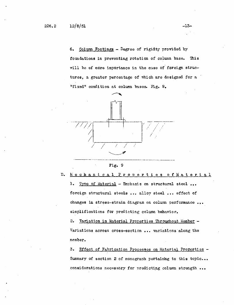
6. Column Footings - Degree of rigidty provided by
foundations in preventing rotation of column base. This
will be of more importance in the case of foreign struc-
tures, a greater percentage of which are designed for a
"fixed" condi tion at column bases. Fig. 9•
..- -_ ...._--_.._.__../ .' /_._-/../ -;-;
. ////
/ / / / I/
i /
Fig. 9
D. M e c han i cal Pro per tie s 0 f Mat e ria 1
1. Type of Material - Emphasis on structural steel ..0foreign structural steeis ••• alloy steal ••• effect of
changes in stress-strain diagram on column performance
simplifications for predicting column bohavior.
.,.
2. Variation in Material Properties Throughout Member -
Variations across cross-section ••• variations along the
member.
3. Effect of Fabrication Processes on Material Proporties -
Summary of section 2 of monograph pertairong to this topic •••
considerations necessary for predictip.g column strength •••
226.2 12/8/51 -14-
riveting ••• welding ••• punching ••• cold rolling •••
strain hardening an d aging ••• Bauschinger...forming
effect.
4. Residual Stresses due to Fabrication Proces~es -
Residuals due to cooling after rolling and due to welding,
local hoating, cold bending ••• influence of shape and
size of cross-section on magnitude of residual stress.
E. Tim e E f e c t s
1. Impact: Blast Loading - Dynamic response of columns •••
elastic and inelastic behavior.
IV. .Q. C K NOW LED G MEN T S
The chart prosentedin Section II is the. result of a gradual
development. The original suggestion to nrepare a chart to cover
a much broader field was made by Mr. Jonathan Jones. Others who
have participated in tho arrangement are Dr. Bruce Johnston, Dr. Knud
E. Knuds~nJ Dr. C. H. Yang, and Mr. Robert L. Ketter•
.~ considerable amount of ~~terial has also been drawn from
references 3, 4 and 6 which could not be acknowledged conveniently
in the text.

12/8/51
Appondix .Q.
TENT~TIVE OUTLINE OF CH~PTER HElDINGS
Bleich: liThe Buckling Strength of Meta.! Structures"
-15-
~ book of Ithe above ti tle is scheduled to bf\ published as
an Engineering Societies Monograph in J.~uary, 1952. ~~e following
topics WElre originally proposEld in a 1ntter dated June 23, 1947.
llilvisions have naturally been made since that timo. Compression
members other than columns for bridgf:1s and buildings are also treated
in tho work~
1. The Fundamental Features of the Buckling Problem
2. The M::l.thematical Treatment of Stabili ty Probloms in Structural.4.nalysis
3, . Buckling of .cd.xially Loaded Columns. The Elastic and InelasticBange of Buckling
4. Built-Up Columns
5. Built-Up Columns Raving Variable Moments of Inertia
6. Eccentrically and Laterally Loaded Columns
7. Bending and Twisting of ~h1n-Walled Mombers
8. Buckling of Compressi on MembArs Having T '- C '0n- Cross Section j
Torsional Buckling
9. Lateral Buckling of I-Shaped Boams Subject to Loading in thoPlane of the Web
10. Elastic Stability of Frameworks Having Stiff Joints
11. Compressive Strength of Tapered Str~tq
226.2 12/8/51-16
~ppendlE A
12. Buckling Strength of Members Considered as Part of .~ Truss
13. Compression Members in Rigid Frames
14. Buckling Strength of .~~ia11y Loaded Columns Elastically Supported at Intermediate Points
15. The Three-Dimensional Column Problem
16. Buckling of Roct'angular Plates .~cted Upon by Compressive Stressosin Their Planes .~ong Two Opposite Edges
17. Compressed Plates HaVing Longitudinal Stiffeners
18. Compressed Rectangular Plates Transversely Loaded
19. Elastic Stability of Web Plates in Girders

... 226.2 12/8/51
A P pen d i x B
LundquiC!t Survey(4)
SUBJECT CL~SSIFIC~TION
-17-
I. Bending Deflection - This group contains problems relatingto columns that fail by bending deflection~ Typical for thegroup are the following problems:
Axial force wi th end momen tEccentricitiesAxial force and end moments with transverse loads;
Beam-ColwnnsDesign of columns with perforated cover platesBuckling load for arches
II. Combined Bending and Twist -Typical subjects of the groupare:
Angle & tee strutsBuckling of compresSion flange of beams
III. Local Buckling -Thi s group includes those twes of membersthat fail by local buckling of the cross-section. Examplesare:
~ocal instability failures of columnsPlates and shells - with or without stiffeners;
cylinders
IV. Bracing Members - Typical subjects of this group are:
Desi gn of column bracing; evaluation of bracing effect on strength
Bracing for compression flange of beam
V. Plate Grider -'Typical subjects of this group are:
Design of intermediate stiffeners of a plate girderBuckling of gi rder web
VI. Through Bridge Desip;n Problems
VII. Miscellaneous
Material properties of various alloysTflsting methodsSpecifications, handbooks, booksTime and impact effects
VIII. Non-Metallic Colwnns
IX. Research Facilities and Suggestions for Research
~esponse to questionnaires