Embed Size (px)
Citation preview

The Centre for Sustainable Building (ZUB)* A Case Study
Dietrich Schmidt Tekn. Lic. 1,2
1 KTH-The Royal Institute of Technology. Division of Building Technology. Brinellvägen 34. SE-100 44 Stockholm. Sweden. Phone: +46 8 790 8716. Fax: +46 8 411 8432. E-mail: [email protected] 2 ZUB-Centre for Sustainable Building. Gottschalkstrasse 28a. DE-34127 Kassel. Germany. Phone: +49 561 804 1871. Fax: +49 561 804 3187. E-mail: [email protected]. 1. INTRODUCTION The primary energy demand of residential and commercial buildings still counts for about one third of the total world energy demand (ECBCS 2002). Therefore, energy efficient building with the lowest possible impact on our natural environment is much more than a demand, it is a need in the entire building process. The ZUB office building is an example of how new low temperature heating / cooling systems and strategies have been implemented and new environmentally friendly building materials can be used. It illustrates how new efficient systems and strategies can be realised in practical building projects.
Figure 1 The office building of the Centre for Sustainable Building (Meyer 2001) Nowadays an environmentally friendly and sustainable building process is an interdisciplinary task. Only a close teamwork of people from different building related disciplines makes it possible to face the challenge of answering these questions and real life
* Zentrum für Umweltbewusstes Bauen; Kassel, Germany.
problems. That is one reason for the foundation of the Centre of Sustainable Building at the University of Kassel, Germany. But, not only building research and the development of integrated planning processes in the field of building are conducted within the walls of the centre. Moreover, the centre is a platform for the fast implementation of research results into practical building processes. It offers a variety of different services in research and development, in education for all kinds of people who are interested in building (professionals and non-professionals). Furthermore, public relation activities are carried out at ZUB to introduce the ideas of better, more efficient and reliable building with the smallest possible impact on the environment. The building of ZUB is an example of what today's state of the art technology of low energy demand and sustainable building can look like. 2. THE BUILDING CONCEPT The office building of the Centre for Sustainable Building is situated at the University of Kassel, in an old urban neighbourhood. The new building of the ZUB closes a gap between an ensemble of old houses. An atrium, used as a light gap, which contains the entrance zone and the staircases, joins the old brick building of the Faculty of Architecture to the modern concrete construction, joining them to form a combination of old and new (see Figure 1).
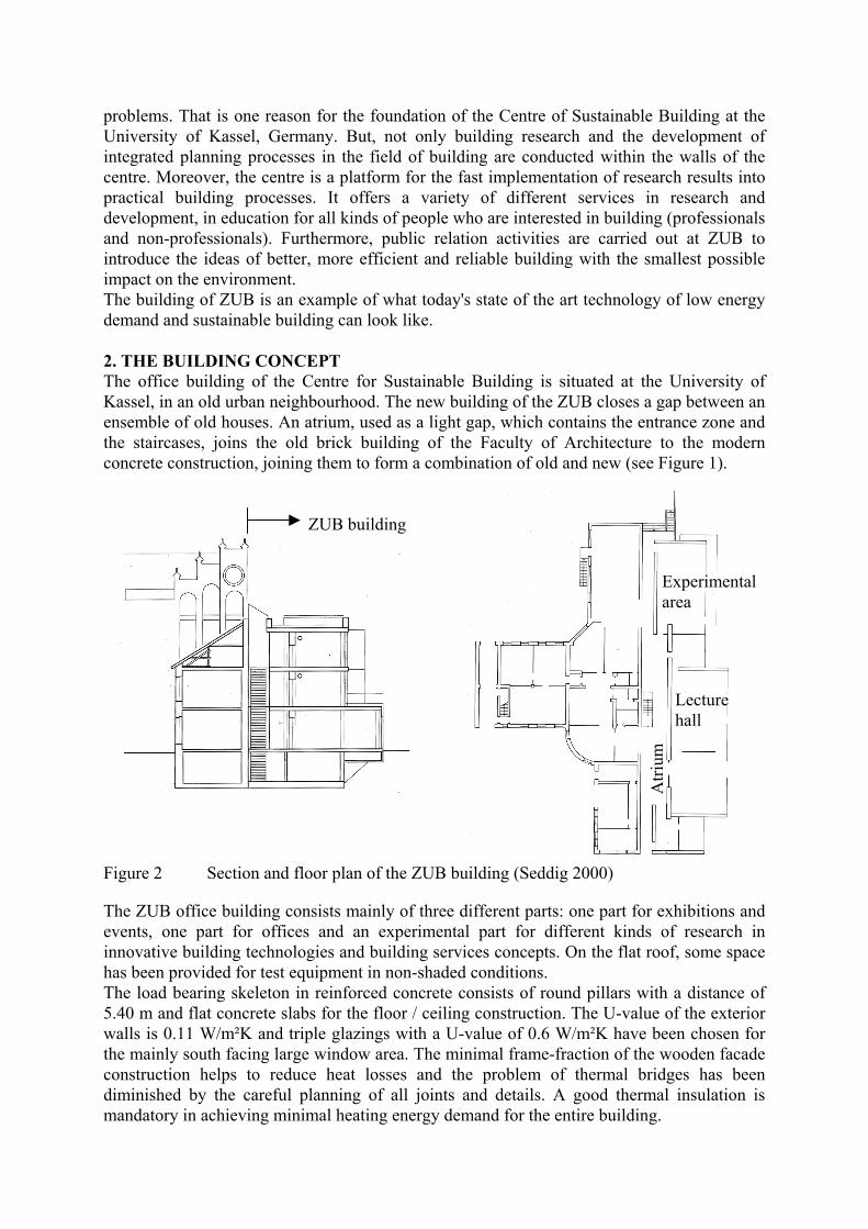
Figure 2 Section and floor plan of the ZUB building (Seddig 2000) The ZUB office building consists mainly of three different parts: one part for exhibitions and events, one part for offices and an experimental part for different kinds of research in innovative building technologies and building services concepts. On the flat roof, some space has been provided for test equipment in non-shaded conditions. The load bearing skeleton in reinforced concrete consists of round pillars with a distance of 5.40 m and flat concrete slabs for the floor / ceiling construction. The U-value of the exterior walls is 0.11 W/m²K and triple glazings with a U-value of 0.6 W/m²K have been chosen for the mainly south facing large window area. The minimal frame-fraction of the wooden facade construction helps to reduce heat losses and the problem of thermal bridges has been diminished by the careful planning of all joints and details. A good thermal insulation is mandatory in achieving minimal heating energy demand for the entire building.
Experimental area
Lecture hall
Atri
um
ZUB building

Table 1 Main building facts Volume 6882 m3 Building part U-valueNet floor area 1732 m2 Exterior walls 0.11 W/m2KMain floor space 830 m2 Roof 0.16 W/m2K Windows 0.80 W/m2KArea/volume ratio 0.34 m-1 Wall/floor against ground 0.26 W/m2K Mean U-value 0.32 W/m2KCalculated heating demand (acc. to energy code WSVO’95) 5.3 kWh/m³a or 16.5 kWh/m²a Costs: Construction Services equipment Building costs per volume 249 €/m³ 97 €/m³ 346 €/m³ per net floor area 988 €/m² 387 €/m² 1375 €/m²
Figure 3 Inside view of an office room (Meyer 2001) 3. THE ENERGY CONCEPT The office has been planned as an example of a low energy building. To reach this aim, the planned annual heating demand was projected as less than 20 kWh/m². It turned out to be 16.5 kWh/m², which is only 27% of the limiting maximal value, according to the German Energy code “Wärmeschutzverordnung 95”. To save electrical energy, both natural lighting and even ventilation strategies have been implemented. Solar gains are utilised through the glazing of the south facing façade. At the same time, a good thermal and indoor comfort for the occupants was a major demand from the building owner. To monitor the aims and verify the concepts and achievements, an intensive research project for "solar optimised building"∗∗ is currently being run. Over a period of four years, all the planning and construction processes are being followed up and, for at least two years, measurements of all important parameters of this building are being drawn out. Approximately 1300 measurement points, such as temperatures and heat and energy flows, are being monitored. In addition, the thermal / indoor comfort and indoor air quality is being ∗∗ Solaroptimiertes Bauen; Teilkonzept 3, research programme funded by the German Ministry of Economy and Technology
+ =

reported and controlled. Studies on the building behaviour are being done in two especially equipped office rooms. Detailed system studies on components (heating and ventilation system) are being drawn out, the entire building is supervised, and the overall energy consumption is being reported. Furthermore, the ZUB office building is a demonstration project for the IEA ECBCS Annex 37 “Low Exergy Systems for Heating and Cooling of Buildings”. 3.1 Systems for heating and cooling To achieve the heating and cooling of the offices using one system, only a hydronic conditioning system with embedded pipes has been chosen. In the case of heating, the system works with low inlet temperatures (approx. 24° C, outdoor temperature dependent). When cooling is necessary, pipes in the floor slab construction of the basement, the ground heat exchanger, cool the water. Ground coolness, a renewable and environmental energy source is utilised and a mechanical cooling machine is not required. The conditioning concept shows how a low energy system can be designed using today’s technologies.
2nd floor
1st floor
Ground floor
Basement
Thermal insulation
Thermal insulation
Thermally activated concrete slab
Thermally activated concrete slab
Thermally activated concrete slab
Thermally activated concrete slab,ground heat exchanger
Activated surface layer
Activated surface layer
Activated surface layer
Figure 4 Position of the different layers of pipes in the concrete slabs As shown in Figure 4, the pipes are embedded in the concrete floor slabs and in the upper floor construction. The slabs are thermally activated and in addition, a conventional floor heating system has been placed on top of them to test the properties of different systems and their advantages. Since each room has its own heating circuit, individual regulation of the thermal conditions is provided. Normally, the systems operates with a low constant inlet

temperature, using the self-regulation effect of this system. It is not possible for the room temperature to exceed the inlet temperatures of the pipes and if the room temperature is higher than the inlet temperature, the system will cool, even in the case of heating. The thermal comfort in these offices is very high because of the even and relatively high surface temperatures. 3.2 Ventilation strategies To reduce ventilation heat losses, mechanically balanced ventilation using heat recovery with two cross flow heat exchangers in a series and a thermal efficiency of 0.8 has been installed. In the normal operation mode, fresh air is supplied directly to the office rooms and exhaust air is extracted from the atrium, then transported to the heat recovery unit. For research purposes, the air flow direction is reversible. The fresh air can be supplied to the central atrium and the exhaust air extracted from the office rooms.
Figure 5 Fresh air supply directly to the
offices and return air via the atrium (Hausladen 2000)
Figure 6 Fresh air supply to the atrium and exhaust air from the offices (Hausladen 2000)
The air flows are regulated via indoor air quality sensors (VOC) and the ventilation is demand controlled. The design air flow, with 4000 m³/h, is too low to supply the offices and the fully occupied lecture hall, which has its own direct ventilation supply from the AHU (Air handling unit). When the overall delivered airflow is not sufficient, the offices are ventilated by natural means. Fresh air is supplied via the open windows in the offices and exhaust air leaves the building through openings at the top of the atrium. The stack effect of this high building helps in ventilating without fans. For this ventilation strategy, no heat recovery can take place, but it has great advantages for night cooling. The building structure is cooled during the night by a massive flow of cold ambient air. 4. OTHER SYSTEMS There is a clay wall, made from massive unbaked clay bricks, in the centre of the building and on all floors. This wall, with its great heat capacity and the capability of dampening fluctuations in humidity, can be seen as a climate wall. It also provides the space necessary for electrical and ventilation installations. The function of this wall is also monitored. The building is equipped with a building management system. All building service functions are controlled and the components, like ventilation and heating equipment, are regulated. The measurements for the research programme are done via the building management system. An optimisation of particular building components will be conducted, based upon these values.

Furthermore, new strategies for energy management systems in buildings are going to be developed and tested.
Figure 7 View inside the atrium, it shows the open thermal masses and the internal clay
wall used for all the installations (right hand side) (Meyer 2001) 5. CONCLUSION The ZUB building is actual proof that it is possible, using today’s construction technology, to combine the demand for energy efficiency with sustainable building. This can only be achieved by having a well-designed integral planning process and a close teamwork of all participating parties. An example of this is, shown by ZUB, where the hydronic heating/cooling system has been merged into the building structure, an entirely new challenge for planers and builders. Measurements (Approx. heating energy 26.7 kWh/m²a, approx. electricity consumption 10.7 kWh/m²a) of the first heating period, indicate that the demand for low energy use has been fulfilled. 6. ACKNOWLEDGEMENT The author wants to thank the German Ministry of Economy and Technology and the Swedish Council for Building Research for financing the research work on this project. 7. REFERENCES ECBCS 2002. Energy Conservation in Buildings and Community Systems Programme. International Energy Agency. Homepage http://www.ecbcs.org. Hausladen G. (ed.) 2000. Innovative Gebäude-, Technik und Energiekonzepte. Oldenburg Industrieverlag, Munich. Meyer C. 2001. Photos of ZUB. Meyer Architekturphotographie. Cologne. Schmidt D. 2001. Models for Coupled Heat and Mass Transfer Processes in Buildings – Applications to Achieve Low Exergy Room Conditioning. Tekn. Lic. Thesis. ISRN KTH-BYT/R-01/185-SE, KTH, Stockholm. Seddig I. 2000. Architectural drawings and planning of ZUB. Jourdan & Müller ° PAS, Seddig Architekten. Kassel.