Embed Size (px)
Citation preview

The Cause of Cracking inPost-Tensioned ConcreteBox Girder Bridges andRetrofit Procedures
Walter Podolny, Jr.Bridge DivisionOffice of EngineeringFederal Highway AdministrationWashington, D.C.
On the premise that "Those who ig-nore history will be condemned to
relive it," this paper attempts to docu-ment those types of problems that leadto cracking in post-tensioned concretebox girder bridges and have been en-countered in both Europe and theUnited States.
These problems are not limited tothose of prestressed box girder bridges,but may occur in other types of struc-tures with similar conditions and de-tails. Problems are generally attributedto poor quality control, inadequate de-sign details, inferior workmanship, orlack of understanding as to how thestructure will behave, either through ig-norance or because a particularphenomenon is unknown to the currentstate-of-the-art, or a combination of all
these factors.Cracking in post-tensioned concrete
box girders generally results, in a broadsense, for the following reasons: inade-quate flexural and shear capacity, non-consideration of thermal stresses, insuf-ficient attention to stresses developedby curvature of tendons, improper or in-appropriate construction techniques,lack of quality workmanship to meet thetolerances necessary for problem freestructures, and understrength materials.
It should also be noted that cracks arenot totally avoidable in post-tensionedconcrete box girder bridges, since not allportions of the structure are precom-pressed in three directions and localconcrete shrinkage is not always con-trollable. Certain cracks may not bestructurally serious, while others are. It
82

is, therefore, important for the structuralengineer to determine the structuralsignificance of a crack and its effect onthe serviceability of the structure.
In general, in today's technology it isvery rare that the triggering mechanismcan be traced to a single source, Each ofthe sources cited above, when taken in-dividually, usually produce stresses orcverstresses that are minor and withinallowable limits. However, if one or anumber of the sources is ignored or in-advertently overlooked, a superpositionof stress can occur such that the capacitycf the concrete is exceeded and the onlyrelief the structure has from this over-stress is to crack.
Therefore, it can be seen that it is verydifficult to diagnose a specific triggeringmechanism. It generally requires anextensive investigative effort, usually bya. process of elimination, to determine asingle or small group of probable causa-tive factors.
When serious and/or extensivecracking distress occurs in a project,there may he a concern for the integrityof the structure. This usually results indelay of the project, investigation, ret-rofit measures, determination of liabil-ity and legal involvements, which be-comes costly in terms of both time andmoney. It is hoped that the data pre-sented in this paper will help to dissipatethe occurrence of these problems to thebenefit of both the engineering and con-struction professions.
FLEXURAL CRACKINGFlexural cracking is associated with
tensile stresses that exceed the tensilecapacity of concrete. They are generallyfound, in continuous girders, at the bot-tom of the girder in positive momentareas and at the top of the girder innegative moment areas (Fig. 1). In boxgirders, positive moment flexure crackswill traverse the bottom flange (soffit)width and if severe enough will propa-
SynopsisThe appearance of distress in
the form of cracking in any con-crete structure is one of concernand consternation to all parties in-volved. It is evidence of an unf a-vorable stress condition and if seri-ous enough could affect the struc-ture's integrity. Cracking may occurfor a number of reasons but usuallyis the result of the interaction ofseveral causative factors. Thesefactors taken individually may beminor but when superimposed canresult in distress.
This paper presents documenta-tion of problems that have led tocracking in post-tensioned con-crete box girder bridges in Europeas well as in the United States. 1tdiscusses cracking resulting frominadequate flexural and shearcapacity, thermal stress cracking,and cracking resulting from tendoncurvature and tendon misalign-ment. Also discussed are possibleretrofit measures.
The intent of this paper is tobring these problems to the atten-tion of the engineering and con-struction professions with the hopeof precluding their recurrence.
gate in the webs. Flexure cracks in thetop of the section, in the negative mo-ment area, occur less often since there isgenerally a moment redistribution thatoccurs which reduces the tensile stress-es in this area.
In segmental box girders, flexurecracks will generally occur in or near thesegment joints (Fig. 2). The crack widthat the bottom can be on the order of0.004 to 0.008 in, (0.1 to 0.2 mm). As thecracks propagate up to the top flange,they will become fine microcracks.
PCI JOURNAL/March-April 1985 83

^^K^PATTERN
inflectionpoints MOMENT DIAGRAM+M
Fig. 1. Flexural cracking zones.
Flexural cracks can he small (mi-crocracks) and the structure may appearto be intact. However, the width of theseflexural cracks can vary and becomequite large, 1 to % in. (3 to 10 mm),under the effects of external loading,such as dynamic traffic load or thermalgradient.
In areas near the support the effect ofshear will be superimposed upon theflexural stresses producing, after initialvertical cracking, cracks that are in-clined and become more and more diag-onal in the webs, which may indicateinsufficient shear strength (Fig. 3).
This type of cracking will be accom-panied by deformation in the structure,visible and measurable deflection.Cracks of this type pose a risk to thereinforcement, prestress or conven-tional, that traverse the crack from corro-sion or from fatigue damage under largeand frequent stress variation.
Considerable care must be exercisedin diagnosing the cause of cracks in thispattern. Inadequate flexural capacitymay or may not necessarily be thecausative factor. Excess tension andsubsequent cracking behind blister an-chorages can produce similar cracking(this effect will be discussed in a sub-sequent section). Therefore, cracking ofthis type may have its origin in inade-
quate flexural capacity, cracking behindanchorage blisters or a combination ofboth.
Causes of inadequate flexural capacityare varied in origin and it is seldom thata single cause will produce significantcracking. More generally, there are anumber of causes which by themselvesare insignificant, but when acting inconcert with other causes produce sub-sequent cracking.
The more prevalent causes are as fol-lows:
(a) During Design1. Inadequate consideration of, or un-
derestimation of, stresses resulting frommoment redistribution,
2. Underestimation of thermal stresses(expansion or contraction),
3. Lack of consideration of, or under-estimation of, thermal gradient.
4. Overestimation of initial prestressresulting from optimistic coefficients offriction and wobble.
5. Underestimating relaxation loss inprestressing.
6. Selection of a tendon profilewhereby a large variation of prestresseccentricity occurs (Fig. 4), and notchecking the stresses at critical loca-tions.n
84

Fig. 2. Flexural cracks.
verticalbendingcracks
f '
combinedbending-shearCracksnear support
Fig. 3. Flexural cracks.
cantilever tendons continuity tendons
joint(i)sections at rightand left checked
unchecked zonewhere crackingdevelops
joint(i*I)sections at rightand left chocked
Fig. 4. Unverified zone of cracking.
PCI JOURNALIMarch-April 1985 85

point ofinfI -tinn
la!
faulting
(b)
Fig, 5. Shear cracking.
(b) During Construction1. Losses as a result of excessive fric-
tion resulting from crushed tendonducts.
2. Displacement of poorly securedtendon ducts which then alters the ec-centricity and also produces additionalfriction.
3. Lack of isolation from the concreteof tendon couplers. If the coupler is po-sitioned such that it cannot freely moveas the tendon elongates under stressing,the prestress force distribution is al-tered.
4. Failure of strands or wires in a ten-don.
(c) Excess Permanent Loads1. Underestimating the weight of con-
struction equipment and permanentnonstructural loads (roadway thickness,overlay, utility lines not originallyplanned, etc.).
2. Accidental displacement of formsbefore or during concrete placement re-sulting in a greater thickness andheavier deck. The opposite can also
occur whereby the thickness is reducedresulting in decreased concrete area toaccommodate stress.
3. Underestimation of the voiuminalmass of concrete, especially wheredense aggregates such as those of basal-tic origin are used.
(d) Secondary Stresses andOverloads
These are stresses experienced duringconstruction and service life for which itmay not have been designed.
1. Differential settlement of supportsor movements of pier foundations whichmodify stresses and/or deformations.
2. Cracks caused in the concrete dur-ing or after setting that result frommoving construction loads or shifting offormwork.
3. Faulty concreting sequence thatcan cause cracking as a result of differ-ential shrinkage.
4. Overload from heavy truck trafficand accompanying dynamic effects.
5. Failure to recognize local effectssuch as, for example, curvature of ten-dons or stresses behind anchorages.
86

t fX
longitudinalstresses
draped cantilever tendons
Fig. 6. Shear forces.
SHEAR CRACKINGShear cracks occur in the webs and are
perceptibly inclined at approximately a45 deg angle. They normally manifestthemselves in a zone between the sup-port and an inflection point (Fig. 5a).The web reinforcement traversing thesecracks is subject to stress variationswhich can cause bond failure andfatigue damage. In addition, at the limit,the reinforcement can yield. This mayresult in the faulting of the intradoswhich is usually not visible to the eye(Fig. 5b), but can be instrumentallymeasured.
Most of the causes of flexural cracksare also responsible for shear crackssince a change in bending moment au-tomatically changes shear stress:'
1. Insufficient prestressing2. Excess permanent loads3. Secondary stresses4. Thermal effectsShear cracks can also be initiated by
bending cracks or high tensile stressesbehind tendon anchorages. The fol-lowing design oversights may also con-tribute to the formation of shear cracks:
1. Lack of recognition of shear dis-tribution in the webs of multicell gird-ers. The transverse design of the sec-tion does not take into account the trueflexibility of the cross section. (This ef-fect will be discussed in a subsequentsection.)
2. Lack of double checking to the rightand left of a section where a tendon ter-minates.
3. Failure to recognize the effect of in-clination of continuity tendons in vari-able depth girders. Although the verticalcomponent of a single tendon may besmall, if there are a large number of ten-dons they can create a significant shearforce.
The total net shear force, V, is thesum of the following terms (Fig. 6):3
1. Shear force due to applied loadsequals V,
2. Reduction due to verticaI compo-nent of draped tendons, where usedequals –E P sin a.
3. Increase due to inclination of con-tinuity tendons in the bottom flange forvariable depth girders equals +1 P sinIs.
4. Reduction due to the inclined prin-
PCI JOURNALJMarch-April 1985 87

typical diagonal cracksIT-max. oper+ing 0.02" (0.6 mm)
intermediate diaphragm
PARTIAL ELEVATION
Fig, 7. Web cracking of center web.
cipal compressive stresses in the bottomflange (usually called the Resat effectafter the engineer who first studiedmembers of variable depth) equals–ff tB tany.Thus:Vo –V –YEP sin a+IPsing –f. tB tan y
Cracking Produced by IncorrectDistribution of Forces
This example 3.4 is one of a two-cell,variable depth, box girder bridge con-structed by the balanced cantilevermethod and consisting of five spans of210, 370, 370, 390, and 230 ft (64, 113,113, 119, and 70 m). External webs are13 in. (340 mm) thick and the center webis 12 in. (300 mm) thick. Because thebridge was subsequently intended tocarry monorail pylons, two intermediatediaphragms were provided at the thirdpoints of each span, as indicated in Fig.7.
Longitudinal prestress was applied bystraight tendons in the top flange and
vertically curved tendons in the bottomflange. Vertical prestress was applied inthe webs to control shear stresses. Diag-onal cracking was observed in the centerweb, only near the intermediate dia-phragms, with a maximum crack openingof 0.02 in. (0.6 mm). In addition therewas cracking in the bottom flange,
A complete investigation of the prob-lems encountered revealed that crack-ing was the result of the superposition ofseveral adverse effects, any of whichmight have been harmless if consideredseparately:
1. The computation of shear stressesfailed to take into account the adverseeffect (usually neglected) of the verticalcomponent of continuity prestress in thebottom flange of a girder with variabledepth. The curvature of continuity ten-dons distributed in the bottom flange issuch that a downward reaction is pro-duced at the webs that is additive to theshear in the web (see above).
2. The distribution of shear stresseswas made under the conventionalstructural analysis assumption that the
88

(a) conventional assumptionof transverse rigidity
(b) transverse deformability
Fig. B. Transverse stiffness of a two-cell box.
cross section was rigid and transverselyundeformable (Fig. 8a). However, de-pending upon the stiffness of compo-nent parts of the cross section this as-sumption may be erroneous (Fig. 8b).Conventional analysis, assuming a rigidundeformable cross section, assumesthat a centered loading is evenly dis-tributed among the webs. In fact, acenter loading induces a transverse de-formation in the top and bottom flangeswith a displacement of the center weblarger than that of the external webs.Fig. 9 indicates influence lines for shearin the center web and the external web.The transverse behavior appears verydifferent from that of a transversely un-deformable section and may producecracking in the bottom flange as indi-cated in Fig. 10. For any particular crosssection, a more rigorous analysis is indi-cated than that usually conducted.
3. The vertical web prestress was par-tially lost into the intermediate dia-phragms, and the actual vertical compres-sive stress was lower than assumed.
4. Vertical prestress is usually applied
with short bar tendons and even ifequipped with a fine thread they are notcompletely reliable unless special pre-cautions are taken under close supervi-sion. Even a small anchor set signifi-cantly reduces the prestress force, and itis not unlikely that the actual prestressforce is only three-fourths or eventwo-thirds of the theoretical prestress.
Cracking as a Result of IndirectSupport
The ideal position of bearings at a pieris directly tinder the webs of a box gir-der. The shear from the web is trans-ferred directly from the web to thebearings, and there is need only for asimple inside diaphragm designed totransfer the shear stress, due to possibletorsion moments, to the substructure.However, to avoid spalling the bottomoutside comer of the soffit, the edge ofthe bearing should be a minimum of 2in. (50 mm) clear of the corner. If achamfer exists at the corner, the cleardistance should he measured from the
PCI JOURNALJMarch-April 1985 89

edge of the chamfer (Fig. Ila).A more complicated situation arises
when the bearings are offset with re-spect to the webs (Fig. lib). Mild steelreinforcement and possibly prestressingsteel must be provided in the cross see-
(a) INTERNAL WEB
actual
conventional analysis100
4HH898040
(b) EXTERNAL WEB
tion immediately above the pier to ac-commodate the following:3
1. Suspend all shear stresses carriedby the web under Point A, where a 45deg line starting at the bearing edge in-tersects the web centerline (hatchedarea in the shear diagram).
2. Balance the moment (V x d) in-duced by the hearing effect.
Obviously the most severe situation isthat where a single bearing is used, or apair ofbearings is sufficiently offset, andthat the 45 deg line from the bearingdoes not intersect the web centerline(Figs. lie and lid).
An approach to the determination ofthe forces involved is by means of a trussanalogy,' using trusses with compres-sion struts formed in the plane of thewebs and diaphragms. Fig. 12 shows thetruss analogy for the case of a singlebearing at the centerline of the crosssection. Where the web trusses and thediaphragm truss intersect, the web isstressed in the same manner as if a loadwere suspended from the bottom at theposition of the diaphragm.
Reinforcement requirements shouldhe based upon an ultimate load condi-tion. Suspension reinforcement is re-quired to transfer the ultimate load inthe web to the diaphragm. The resistingsuspension reinforcement in the webshould be in addition to the normalshear reinforcement.
This suspension reinforcementshould, in addition, be distributed in the
60
40
20
Fig. 9. Shear influence lines.
Fig. 10. Cracking pattern in bottom flange.
90

web
I R 1\v(
I )
distribution ofshear stressin web
V ^ (b)
I(c)
Fig. 11. Position of bearings.
hatched area of the intersection zone(Fig. 12d), such that 70 percent of it islocated in the web.' It should he the fulldepth of the girder and adequately an-chored.
In many instances, provisions aremade (or should be made) for futurejacking up of the superstructure in theevent the bearings require replacement.The design drawings should indicatethe intended position of the jacks andthe consequences of this temporary re-positioning of reactions should be ac-commodated in the design.
THERMAL STRESSCRACKING
The current AASHTO Specifications°recognize thermal expansion and con-traction in the design of bridge struc-tures. The rise and fall of temperatureshould be determined for the site of thestructure under consideration. In gen-eral, AASHTO requirements for tern-
(d)
perature rise and fall of a concretestructure about an assumed temperatureat time of construction is as follows:
Type of climate
Temperature
Rise Fall
Moderate climate 30°F 40°F(16.7°C) (22.2°C)
Cold climate 35°F 45°F(19.4°C) (25.0°C)
The thermal coefficient for normalweight concrete is taken as 6 x I0- 11 perdeg F (10.8 x 101 per deg C). Thus, byusing the equation:
e=aIAt (1)
wheree = total change in length Ia = thermal coefficient of
expansion (or contraction)l = length of a member from a
reference pointA t = change in temperature of an
PCI JOURNALIMarch-April 1985 91

(b) CRACK PATTERN
unrestrained memberThe change in length of an unre-
strained member can be determined.Where a member is restrained (fixity ofsupports or friction in bearings) thethermal expansion or contraction is pre-vented by reactions at the supportswhich then cause stresses in the mem-ber. This stress is calculated by assum-ing that the thermal expansion or con-traction first occurs and then forces(reactions) are applied at the restraintsto bring the member hack to its originallength.
From Eq. (1) the strain in the memberis determined as:
E= ell=a At (2)
The change in length of the memberper unit of length accompanying theunit stress "s" caused by the restraint is:
e = s/E (3)
where E is the compressive or tensilemodulus of elasticity. Thus:
e=s1E=aAt ors =EaAt (4)
@ webs
girder depth
supportreaction 2V it
(a) CROSS SECTION d
`4 t
aphragg e
compressi(— tension
reaction 2Vult //I
(c) ANALOGUS TRUSSES
Fig. 12. Indirect bearing support.
jdiaphragm
^ N
web
whichever produces
Ld/2 T— the largest area
(d) PLAN OF DIAPHRAGM/ WEB REGION
92

ambient temperature sun
---`-wind speed A.
re-radiation doorio ^/ asphalt} } 7 qi
\]/cate:iaiproperties
--+- wind speed
ambient temperature
Fig. 13. Thermal response parameters.
From the above, expected movementsor stresses can he determined for sup-port conditions and expansion joints andbearings as appropriate can be provided.However, occasionally distress is stillevident from displaced bearings and/ordamaged expansion joints. Presumably,this distress occurs from unanticipatedtemperature rise or fall.
Although the above consideration hasbeen a traditional approach to thermalstresses in bridge structures, bridge en-gineers have relatively recently becomeaware of another thermal phenomenon,namely, thermal gradient. As a result ofthe poor thermal conductivity of con-crete, a temperature gradient will occurthrough the depth of a concrete mem-ber. The gradient is a function of anumber of variables (Fig. 13) such assolar radiation, ambient temperature,wind speed fluctuations, material prop-erties, surface characteristics, and see-tion shape.
This type of thermal gradient willcause external restraint forces in stat-ically indeterminate structures such ascontinuous girders. If in a continuousbridge the interior supports (points offixity) are released, the structure willattempt to camber upward, assuming an
increase in temperature of the uppersurface with respect to the lower sur-face. Since the structure is restrainedfrom cambering freely, restraint mo-ments and shears are produced (Fig.14)-' 'Z
In prestressed concrete structuresthere may be zones, under dead loadplus prestress, where there is a lowcompressive stress reserve and thestresses due to restraint forces can easilyreach values that exceed the tensilestrength of the concrete. This usuallyleads to vertical cracks very close to in-termediate supports. Cracking as a re-sult of thermal gradients have been re-ported 13 and is considered to he one offour prime causes of cracking in pre-stressed concrete bridges.-' In somecases the thermal gradient stresses canbe larger than the live load stresses.These cracks can be further enhanced oraggravated by stresses resulting frombearing pressure at the supports or ra-dial tendon stresses from curved ten-dons in the support area.12
The magnitude of the restrainingforces is a function of the thermal gra-dient assumed and can be linear or non-linear. Several countries recognize theexistence of thermal gradient and make
PCI JOURNAL/March-April 19B5 93

FREE DEFORMATION
tP ^
P_ = PL1
RESTRAINT FORCES AND MOMENTS
Fig. 14. Moment caused by thermalgradient.
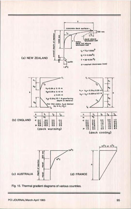
recommendations for their considera-tion in design. Most of these recom-mendations require different shapedgradients and intensities to be evaluated(Fig. 15). However, it should be notedthat they are influenced by localmeteorology and construction practices.
The New Zealand gradient" (Fig.15a) is a fifth power parabola for a depthof 1200 mm (48 in.) with the tempera-ture (T) at the concrete surface related toan asphalt thickness (d) in mm. Thiscurve is used for webs and that portionof the deck not above an enclosed cell,i.e., deck flange cantilevers.
For decks above an enclosed cell alinear curve is used of 5 – 0.054°C per100 nun (4 in.) thickness with the temper-ature (1') at the top surface. A lineartemperature increase from 0°C to 1.5°Cis used over the bottom 200 mm (8 in.)thickness of the section.
For structures shallower than 1400mm (56 in.) the two parts of the solidcurve are to be superimposed. For boxgirders the transverse effects are ob-tained by using the dotted curve. On abridge which is to be surfaced, the tem-porary unsurfaced condition is to bechecked by using a value for(T) of27°C.
Thermal gradient curves used in En-gland 15 are indicated in Fig. 15b for deckwarming and deck cooling. These
curves assume a thickness of surfacingof 40 mm (1.6 in.) for Groups 1 and 2loading and 100 mm (4 in.) for Groups 3and 4. For other thicknesses of surfac-ing, the values of (T) are adjusted ac-cording to prescribed tables that arepresented in the British Code of Prac-tice.
In Australia' the thermal gradientcurve takes the shape indicated in Fig.15c. In France' (Fig. 15d) a linear varia-tion is used with a 10°C gradient used incombination with dead load, shrinkage,and creep. A 5°C gradient is used withall loads (including live load and im-pact).
Currently in the United States thereare no general criteria for thermal gra-dient, although a recommendation ispresented in Ref. 16. However, the Na-tional Cooperative Highway ResearchProgram (NCHRP) has a current Project12-22 titled "Thermal Effects in Con-crete Bridge Superstructures" that willhopefully result in recommendations tobe used for United States practice.
The effects of thermal gradient areusually computed by assuming the gra-dient to be constant throughout thebridge superstructure length, which isnot necessarily the case. Fig. 16 indi-cates the results for the case of a typicalspan fixed at both ends (the case of along structure with many identicalspans). The stress at the bottom fiberdepends upon the following two factors:
1. Variation of height between spancenter and support (ratio ]k 11,, ).
2. Position of the center of gravitywithin the section (ratio c2/h),
The stress increases rapidly when thevariation in depth is more pronounced.For normal proportions the effect of gra-dient is increased by 50 percent in vari-able depth girders compared to constantdepth girders.'
Another source of thermal stress(strain) related cracking is that associ-ated with heat of hydration, subsequentcooling and shrinkage. Heat of hydra-tion is a chemical process that is a func-
94
T
concrete deck surface 1
(a) NEW ZEALAND
iy
ii
} E0
v .Drat
1.5°C
100 mm''' tY
' (deck above, enclo sad Cellwebs deck nol aboveenclosed cell
ty • T(y3 1200)5Yy - 5-0,05d0CT- 32-0.2d*Cd=capful thickness (mm)
__I
Tthi
T2h2
h1.0.3hz6 0.15 mh h2.0.3h 8 0.10 m
50.25 mh '. 0.3h^ (0.1 mtsurlacinp
depth In meters)(tor thin slabs. h 3 1e hmlled
13 by h-hl-h27
h T1 T2 TIll oC
(b) ENGLAND zz 0.2 e.5 3.5 05
0.4 12.0 3.0 1.5
0.6 13.0 3.0 2.0ar 0.8 13.6 3.0 2.5
(deck warming)
Tthi
72h2
h 1 - u14 02h0.25 mh 2 h3 0.25h^0.2 m h` -
h3T3
h4T4
h T T2 T Tm
0.2 2.0 0.5 0.5 1.50.4 4.5 1.4 1.0 3.50.6 6.5 1,8 1.5 5.00.8 7.6 1.7 1.5 6.01.0 8.0 1.5 1.3 6.31.5 6.4 0.5 1.0 6.5
(deck cooling)
10°G ar Soc24°C ^ ^Il
n _c goC0
h
(c) AUSTRALIA v (d) FRANCE
Fig. 15. Thermal gradient diagrams of various countries.
PCI JOURNALMarch-April 1985 95

300
^^` range C2 /h=0.65
E '- 250 C2/h0=0.60yoa i
220— 50 psi for constantn°^ 200 depth and inertia
a f2 Ec(t T)C2Jh0rn 150W 160 Si a -coefficient of.. a cons ant de rth thermal expansiontl7 N
100 oT+tamp eraturegradient
NOTE: For other moduliic° of elasticity mutttplyEc = 5,000,000 psi stress by E/5,000,000
1.0 1.5 2.0 2.5 3.0 h11h0
h 1 h1 T" 18°F f
^' r0LEif2
ELEVATION OF SPAN SECTION AT CENTER
Fig. 16. Effect of thermal gradient on box girder decks.
Lion of the type and amount of cement,thickness of concrete members andtemperature of aggregate, mixing waterand surrounding atmosphere. As a resultof heat of hydration and shrinkage,especially between thick and thin por-tions of a cross section, large residualstresses can be produced which exceedthe tensile strength of"green" concrete.
Thin parts of the cross section willcool faster than adjoining thick partsproducing residual tensile stress andcracking, There is always a potential ofcracking when a thin member is at-tached to a relatively larger member.The thinner member will always hesubjected to a faster rate of temperaturechange (cooling), larger creep andshrinkage than the larger member andthus the thinner member will crack,112
In box girders with thick webs rela-tive to the thickness of the bottom flange,
the bottom thin flange will cool fasterand attempt to shrink at a faster rate thanthe webs and is therefore being re-strained. To relieve tensile strains, pro-duced by restraint of the webs, the thinbottom flange has no other alternativebut to crack (Fig. 17a). In a transversesection, large differences in thicknesscan produce restraining moments whichcan produce horizontal cracks in thewebs (Fig. 17b).
A similar thermal stress (strain) in-duced cracking can occur in staged con-struction whereby the cross section isconstructed in two or more pours re-quiring construction joints. When freshyoung concrete is placed against hard-ened older concrete there is a danger ofcracking. Initially, the fresh concretewill have an increase in temperature re-sulting from heat of hydration, thenwhen cooling occurs the new concrete is
96

crack
crack
b!2
/ nNcracks
Plan
(a) CRACKS IN THIN BOTTOM FLANGE
Fig. 17. Thermal shrinkage cracking.
top flange3rd stage casting
(b) HORIZONTAL CRACKS IN WEBS
web2nd stage castingforms still in place
bottom flange1st stage casting ELEVATION
SECTION
Fig. 18. Web shrinkage cracks.
restrained from shrinking by the olderconcrete.
Usually, because of insufficient lon-gitudinal reinforcement and/or lack ofsufficient bond development betweenthe reinforcement and the young con-crete, there is insufficient capacity forthe younger concrete to resist the re-
straint to shrinkage produced by theolder concrete and cracking of theyounger concrete will occur. If the formsare left in place too long, they will pre-sent a large surface area of friction thatwill also hamper the shrinkage of thenew concrete and thus cause cracking(Fig. 18).'
PCI JOURNAL/March -April 1985 97

segment A segment B
(a) ELEVATION
cons,
(6) CONSTRUCTION STAGES
Fig. 19. Klement Gottwald Bridge.
As an example of temperature varia-tion in a box girder bridge, data extract-ed from Ref. 17 is presented here toillustrate the point. The research effortinvolved the instrumentation and tem-perature data collection in two adjacentsegments near the midspan of an inter-ior span (Fig. 19a) during construction ofthe Klement Gottwald Bridge over theNusle Valley in Prague, Czechoslovakia.Segment A had been previously cast andSegment B is the segment being con-structed, Segment length is 11.5 ft (3.5m) and is cast in three stages as indi-cated in Fig. 19h.
Concrete temperature data obtainedin December 1969 was influenced bythe following factors:
1. Extremely cold ambient tempera-ture. The temperature was below 0°Cand in the final phases of data collectionthe temperature was often below –20°C.
2. Preheating of the concrete mix, be-cause of the low ambient temperature.Hot water was used in preparing the mixsuch that the average mix temperature at
placing was approximately 35°C. Blownhot air was used as a protection againstfreezing; however, the distribution wasuneven.
These conditions are far from normaland the results have to he considered asextreme, nevertheless, the results areindicative of thermal distribution in thistype of cross section.
Temperature distribution during con-struction of Segment B is indicated inFig. 20. Fig. 20a shows the temperaturedistribution 10 hours after casting Stage1. Note that the bottom flange has athickness of 11.8 in. (300 mm). Fig. 20bshows the temperature distribution 20hours after casting Stage 2 (44 hoursafter casting Stage 1). The web thicknessis 23.6 in. (600 nim).
At this point in time the temperatureat Point "a" was 38.6°C. Fig. 20c indi-cates the temperature distribution 24hours after casting Stage 3 (7 days aftercasting Stage 2). The temperature atPoint "b" was 51.1°C and the tempera-ture immediately above this point, Point
98

7 1 Iy 5 (a) STAGE 1
1 1
200 1 1^
1020 30
10 ^.
20 - 1530 25
— point35 10 (b) STAGE 2
30 ----------25— ..20—15
point "c"10 20 1 30 20
30_ipoint "b"40 - 50
20i0'/\0 ,.
(c) STAGE 3-7.5
-10all values are in 0C
Fig. 20. Temperature distribution.
on the surface of the deck, is ap-proximately 20°C and the temperature inthe bottom portion of the web and thebottom flange is below 0°C.
The temperature distribution withtime for Points "b" and "c" with respectto placing Stage 3 is shown in Fig. 21.These curves indicate, as would be ex-pected, a heat dissipation at the surface(Point "c") as compared with the heatdissipation at an internal position (Point"h"). A comparison of the two curves in-dicates a maximum gradient betweenPoints "b" and "c" at 15 hours after
casting Stage 3 as 32.2°C for a verticaldistance of 28,7 in. (730 mm) betweenthe two points.
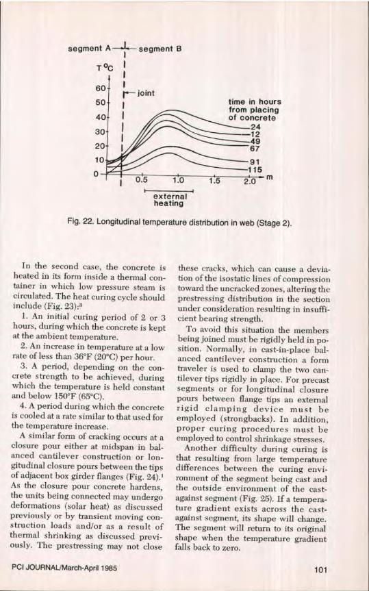
Time-temperature distribution alongthe centerline of the web in the lon-gitudinal direction is shown in Fig. 22.The heavy dashed line indicates thejoint between the previously cast Seg-ments A and B. The curves show, be-tween the points ofO.5to1.2rn(1.6to4ft)from the end of the segment, the influ-ence of the locally effective hot airheating of the segment and also its poorheat distribution.
PC[ JOURNAUMarch-April 1985 99

T oC
60 .56.0 c
50 b r
40
30 X28-0 temperature of concrete at point 'b'
20temperature of concrete at point
1020 40 60 0 10 20 140 t (hours)
0-1-- _ -8.4
-16.6_-20
air temperature inside box
externalheating
Fig. 21. Temperature distribution with time (Points b and c).
These curves are also noticeably in-fluenced by the low temperature of thepreviously cast Segment A and the coolambient temperature. The maximumtemperature gradient decreases gradu-ally after the first few hours of hydrationheat development. This gradual de-crease in gradient is due initially to theheating up of the adjacent segment andlater on to decrease in heat of hydrationand cooling of the web of the segment.
Thin members cool at a faster ratethan thicker members which, therefore,create considerable tensile stress. Whenfresh concrete is cast against old con-crete there is a potential for cracking inthe younger concrete which, when sub-sequent cooling occurs, is hamperedfrom shortening by the older concrete.This usually occurs during the first fewcool evenings when the strength of con-crete is low and low tensile stresses cancause cracking. At this point, becausebond is not sufficiently developed,reinforcement cannot prevent openingof the cracks. Restraint forces due totemperature differences must beminimized to the extent possible byavoiding large differences in thickness
of contiguous members and proper cur-ing procedures.12
There are basically two methods ofheat curing concrete: (1) preheating thefresh concrete before placement in theforms and (2) heat curing the concreteafter consolidation in the forms.'
In the first case the concrete is pre-heated to about 85 to 90°F (30 to 35°C).This operation is achieved in severalways:
1. Steam heating the aggregates — asimple solution that presents the disad-vantage of changing the aggregate watercontent.
2. Heating the water— a solution thathas limited efficiency, because of thesmall proportion of water in comparisonwith the other components (water at140°F raises the concrete temperatureby approximately 20°F).
3. Direct heating of the concrete mixby injecting steam into the mixer itself— the best solution and the one mosteasily controlled.
To avoid heat loss, the forms are gen-erally insulated and some source ofradiant heat is installed inside the seg-ment.
ie
segment A— segment B
T °C
60 —joint50 l
40
30
20
10
00.5 1.0
I
externalheating
time in hoursfrom placingof concrete—24--12—49
67
—91—115
20 m
Fig. 22. Longitudinal temperature distribution in web (Stage 2).
In the second case, the concrete isheated in its form inside a thermal con-tainer in which low pressure steam iscirculated. The heat curing cycle shouldinclude (Fig. 23):3
1. An initial curing period of 2 or 3hours, during which the concrete is keptat the ambient temperature.
2. An increase in temperature at a lowrate of less than 36°F (20°C) per hour.
3. A period, depending on the con-crete strength to be achieved, duringwhich the temperature is held constantand below 150°F (65°C).
4. A period during which the concreteis cooled at a rate similar to that used forthe temperature increase.
A similar form of cracking occurs at aclosure pour either at midspan in bal-anced cantilever construction or lon-gitudinal closure pours between the tipsof adjacent box girder flanges (Fig. 24).'As the closure pour concrete hardens,the units being connected may undergodeformations (solar heat) as discussedpreviously or by transient moving con-struction loads and/or as a result ofthermal shrinking as discussed previ-ously. The prestressing may not close
these cracks, which can cause a devia-tion of the isostatic lines of compressiontoward the uncracked zones, altering theprestressing distribution in the sectionunder consideration resulting in insuffi-cient bearing strength.
To avoid this situation the membersbeing joined must be rigidly held in po-sition. Normally, in cast-in-place bal-anced cantilever construction a formtraveler is used to clamp the two can-tilever tips rigidly in place. For precastsegments or for longitudinal closurepours between flange tips an externalrigid clamping device must heemployed (strongbacks). In addition,proper curing procedures must beemployed to control shrinkage stresses.
Another difficulty during curing isthat resulting from large temperaturedifferences between the curing envi-ronment of the segment being cast andthe outside environment of the cast-against segment (Fig. 25). If a tempera-ture gradient exists across the east-against segment, its shape will change.The segment will return to its originalshape when the temperature gradientfalls back to zero,
PCI JOURNAL/March-April 1985 101

T o f Ow
uj z rt212— W 0Gr1
cca max. temp. <150°F(65°C)o^^ZG
G3—65
^
FORM STRIPPING65 —
2 to 3hItime in hours
¢zput
F~)W w
<<: -J
¢ 0?Ud aw
wZ¢ 0
2iw
OMwI w
Fig. 23. Heat treatment cycle.
cracks
detachments
PLANclosure pour
flange movements
SECTION
closure segment
movements
Fig. 24. Closure pour cracks.
102

ft1fr<h "
-il" fit`
segment conjugatet
end form
gradient in
tr
conjugaty
curingAT °F 1ftempera re
` ambienty' ' temperature
•mot'%"^^'
en tL
Fig. 25. Effect of improper curing of segments in short -line casting.
This will result in match cast surfacesthat are not necessarily parallel fulllength. This condition is evidenced inthe top slab joints; the joints will betight at the curbs and a small gap maybe noticed at the center. The problembecomes cumulative if this conditionexists for subsequent castings. With thetremendous prestressing force, the seg-ments develop longitudinal cracks asthe segments are seated against eachother.
This also results in an unaccountedvariable when evaluating the bridgecamber. For match-cast segments, it isimportant to enclose both the castagainst segment and the segment beingcast in an isothermal enclosure. Thiswill prevent longitudinal thermal gra-
dients being set up which could lead tohorizontal curvature of segments andconsequent lack of matching in thestructure. This effect is particularly sig-nificant for segments with high width tolength ratios (in excess of 6).2 •3
CRACKING AT OR NEARANCHORAGES
Certain anchorage positions, such asan anchorage blister on a thin flange asshown in Fig. 26, should be avoided.Wherever possible, anchorage blistersfor continuity tendons should be placedin a fillet between the web and flangewhere the transverse section has thelargest rigidity. If this type of detail can-
PCI JOURNAL/March-April 1985 103

anchorage
Fig. 26. Anchorage blister position to be avoided.
segment jointweb
anchorageblister
-i
>tendons
cracks vweb
Fig. 27. Cracking at anchorages.
anchorage'blister web
tendonscrackingin joint,
i F J -web
segmenjoints
Fig. 28. Cracking in joint behind anchorage.
104

not be avoided, then particular attentionmust he paid in design and constructionto the zone concerned.3.L8
Cracking will originate in the bottomflange behind continuity anchorageblisters and propagate forward towardthe webs, along a line forming a 30 to 45deg angle with the longitudinal axis ofthe girder (Fig. 27). If the rear face of theblister is located in close proximity to asegment joint, cracking may develop inthe joint (Fig. 28). In some situations thediagonal or herringbone cracks in thebottom flange continue to propagate tothe webs forming a 30 to 45 deg anglewith a horizontal axis (Fig. 29)..2
If the crack reaches a segment joint ,nthe web it may cross the joint, but usu-ally travels vertically up the joint to apoint below the top flange where it maycontinue vertically in the joint, resume adiagonal path in the web proper, orcease to propagate. Obviously, the shear
capacity of the webs will he reducedand failure of the structure may he im-minent.2 It should be noted that thistype of cracking is not symptomatic withanchorage blisters; the same crackingpattern has been observed with anchor-ages embedded in the flange, i.e., noblisters.
It is possible that this type of crackingfrom continuity tendon anchoragesin the bottom flange may join with simi-lar cracks originating from cantilevertendon anchorages in the top flange(Fig. 30). In this situation, the centerportion of the span may become an in-verse "key-stone" (Fig. 31) and im-mediate measures are required to pre-vent collapse of the structure.'
This situation occurred in a box girderconstructed by incremental launching'(Fig. 32..). Permanent prestress wasachieves. by straight tendons placed inthe top and bottom flanges, as required
o^s
Fig. 29. Anchorage cracking propagating to web.
PCI JOURNAL/March-April 1985 105

by the distribution of moments. Duringlaunching an additional uniform pre-stress was applied to the constant depthsingle box section, which produced anaverage compressive stress of 520 psi(3.6 MN/ins). Near each pier there was avertical prestress designed to reduceweb diagonal stresses to allowable val-ues.
During launching a diagonal crackappeared through both webs betweenthe blisters provided in the box for an-chorage of top and bottom tendons. Thecorresponding shear stress was 380 psi(2.67 MN/m 2), and there was no verticalprestress in that zone.
The principal tensile stress at thecentroid of the section was 200 psi (1.4MN/ms), which is far below the crackingstrength of plain concrete. In fact, the
webs of the box section were subjectedto additional tensile stresses due to thedistribution of the large concentratedforces of the top and bottom prestress.The truss analogy shown in Fig. 32 indi-cates clearly that such tensile stressesare superimposed on the normal shearand diagonal stress due to the applieddead load and may therefore producecracking. This could have been pre-vented by extending the vertical pre-stress in the webs further out towardmidspan.
The cause of this type of cracking isthe application of a tendon force to asmall area of slab, in its plane, compress-ing the slab forward of the force in azone of radial compression stresses thatcause tensile stresses behind the pointof application of the tendon force (Fig.
top tendonack
riange crack bottom tendon
Fig. 30. Insufficient lap between anchorages.
flanne cranks
Fig. 31. Symmetrical cracking causing inverted "key-stone."
106

initial load 1490 k/tendon iq no vertical prestress in this zone top tendon pier
average -^ I IIthrow h crack in ' I I I 'compression g t i520 psi stress both webs I ' I i i
380 psi initial load 490 kltendon 7 i I F I
1 4 1 a 1 1 i 4
bottom J
tendon 'PARTIAL LONGITUDINAL SECTION
diagonal tensiondue to prestressdistribution in web
I I ,diagonal crack II ,
I TRUSS ANALOGY
SECTION A-A
Fig. 32. Web cracking under high prestress force.
33). 1,2 Among the parameters that canproduce this type of cracking are thefollowing:'
1. Termination of numerous con-tinuity tendons in a single section, par-ticularly when the joint behind the an-chorages is not compressed by othertendons and when passive longitudinalreinforcement does not traverse thejoints between segments or is inade-quate.
2. Insufficient horizontal offset be-tween tendon anchorages in the top andbottom flanges (Fig. 30).
If this type of cracking andlor failure isto be inhibited, the design, detailing,and placement of reinforcement in thesehighly stressed zones must be carefullyconsidered. Location of blisters must beconsidered and there must he sufficientlongitudinal reinforcement behind theblister or anchorage and sufficienttransverse reinforcement abreast of theanchorage to accommodate the initial
tendon forces. In a recent failure of thistype, after epoxy injection of the cracks,additional external post-tensioning wasprovided to close-up and induce com-pression in open segment joints andcracks.
CRACKS RESULTING FROMVERTICAL CURVATURE OF
SOFFIT TENDONSThis type of distress is associated with
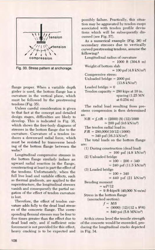
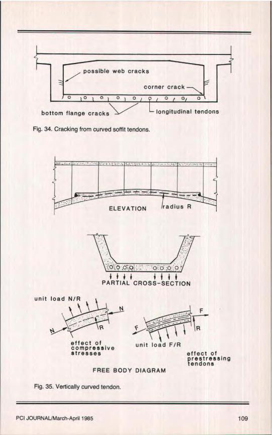
variable depth girders and occurs in thepositive moment area. It is manifestedby longitudinal cracks occurring in thebottom flange, at the juncture of thebottom flange and web, and possibly inthe web (Fig. 34).'
Tendons for continuity or positivemoment prestress may not, or evenshould not, always be located in the fil-let between web and bottom flange.They may be located in the bottom
PCI JOURNAL/March-April 1985 107
t^'\l l l^^ tension
I\\tension
compression
Fig. 33. Stress pattern at anchorage.
flange proper. When a variable depthgirder is used, the bottom flange has acurvature in the vertical plane, whichmust be followed by the prestressingtendons (Fig. 35),
Unless careful consideration is givento that fact at the concept and detaileddesign stages, difficulties are likely todevelop. This is indicated in Fig. 35,which shows the free-body diagrams ofstresses in the bottom flange due to thecurvature, Curvature of a tendon in-duces a downward radial force, whichmust be resisted by transverse bend-ing of the bottom flange between thewebs?
Longitudinal compressive stresses inthe bottom flange similarly induce anupward radial reaction in the flange,counteracting at least in part the effect ofthe tendons. Unfortunately, when thefull live load and variable effects, suchas thermal gradients, are applied to thesuperstructure, the longitudinal stressesvanish and consequently the partial ne-gation of the effect of tendon curvatureis lost.
Therefore, the effect of tendon cur-vature adds fully to the dead load stress-es of the concrete flange. The corre-sponding flexural stresses may be four tofive times greater than the effect due todead load only, and if sufficient rein-forcement is not provided for this effect,heavy cracking is to be expected and
possibly failure. Practically, this situa-tion may be aggravated by tendon cuspsassociated with tendon profile devia-tions which will be subsequently dis-cussed (see Fig. 57).
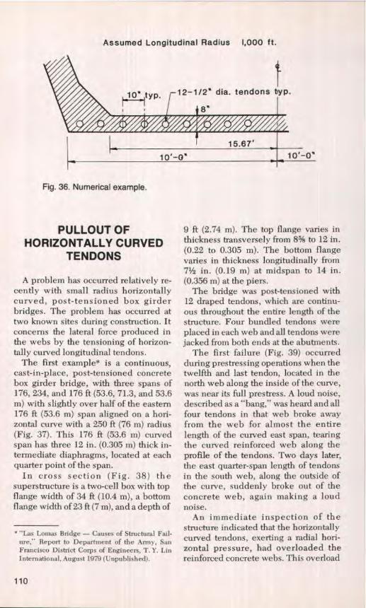
As a numerical example (Fig. 36) ofsecondary stresses due to verticallycurved prestressing tendons, assume thefollowing:'
Longitudinal radius of curvature= 1000 ft (304.8 m)
Weight of bottom slab= 100 psf (4.8 kN/m2)
Compressive stress:Unloaded bridge = 2000 psi
(13.8 kN/m2)
Loaded bridge = 0Tendon capacity = 280 kips at 10 in.
spacing (1.25 MNat 0.254 m)
The radial load resulting from pre-stress compression is then determinedas:
NIB — f. t/R = (2000) (8) (12)/1000= 200 psf (9.6 kNlmz)
The tendon radial load is:FIR = 280,0001(10/12) (1000)
— 340 psf (16.3 kN/m2)
The total loads on the bottom flangeare:
(1) During construction (dead load)= 100 psf (4.8 kN/mg)
(2) Unloaded bridge= 100 — 200 + .340= 240 psf (11.5 kNlm')
(3) Loaded bridge= 100 + 340= 440 psf (21 kN/m2)
Bending moment= w12/12= 9 ft-kips/f} (40,000 N-m/m)
Stress in the bottom flange(uncracked section):f= MIS
= (9000) (12)1(12 x 8216)= 840 psi (5.8 MN/m2)
At this stress level the tensile strengthof the concrete would be exceeded, pro-ducing the longitudinal cracks depictedin Fig. 34.
108
Cpossible web cracks
corner crack
1 0 t n 1 0 0) Q / 0 Oj 0
bottom flange cracks- L longitudinal tendons
Fig. 34. Cracking from curved soffit tendons.
f4^;E 1i i.^.PARTIAL CROSS-SECTION
unit load N/Rt ^ N
/^^ r Pt
effect ofcompressiveStresses
F
unit load FIReffect ofprestressingtendons
FREE BODY DIAGRAM
Fig. 35. Vertically curved tendon.
PCI JOURNAUMarch-April 1985 109
Assumed Longitudinal Radius 1,000 ft.
Fig, 36. Numerical example.
PULLOUT OFHORIZONTALLY CURVED
TENDONS
A problem has occurred relatively re-cently with small radius horizontallycurved, post-tensioned box girderbridges. The problem has occurred attwo known sites during construction. Itconcerns the lateral force produced inthe webs by the tensioning of horizon-tally curved longitudinal tendons.
The first example* is a continuous,cast-in-place, post-tensioned concretebox girder bridge, with three spans of176, 234, and 176 ft (53.6, 71.3, and 53.6m) with slightly over half of the eastern176 ft (53.6 m) span aligned on a hori-zontal curve with a 250 ft (76 m) radius(Fig. 37). This 176 ft (53.6 m) curvedspan has three 12 in. (0.305 in) thick in-termediate diaphragms, located at eachquarter point of the span.
In cross section (Fig. 38) thesuperstructure is a two-cell box with topflange width of 34 ft (10.4 m), a bottomflange width of 23 ft (7 m), and a depth of
• "Las Lomas Bridge — Causes of Structural Fail-ure," Report to Department of the Anny, SanFrancisco District Corps of Engineers, T. Y. LinInternational, August 1979 (Unpublished).
9 ft (2.74 m). The top flange varies inthickness transversely froth 8% to 12 in.(0.22 to 0.305 m). The bottom flangevaries in thickness longitudinally from71/2 in. (0.19 m) at midspan to 14 in.(0.356 m) at the piers.
The bridge was post-tensioned with12 draped tendons, which are continu-ous throughout the entire length of thestructure. Four bundled tendons wereplaced in each web and all tendons werejacked from both ends at the abutments.
The first failure (Fig. 39) occurredduring prestressing operations when thetwelfth and last tendon, located in thenorth web along the inside of the curve,was near its full prestress. A loud noise,described as a "bang," was heard and allfour tendons in that web broke awayfrom the web for almost the entirelength of the curved east span, tearingthe curved reinforced web along theprofile of the tendons. Two days later,the east quarter-span length of tendonsin the south web, along the outside ofthe curve, suddenly broke out of theconcrete web, again making a loudnoise.
An immediate inspection of thestructure indicated that the horizontallycurved tendons, exerting a radial hori-zontal pressure, had overloaded thereinforced concrete webs. This overload

tN
I
176' 234' _ 176`
Lam;
Fig. 37. Bridge elevation and plan.
r^
14 123'
Fig. 38. Typical cross section.
PCI JOURNALIMarch-April 1985 111

Fig. 39. Horizontal pullout of curved tendons (courtesy of T. Y. Lin).
Abt. 1
Pier 2 tIN11
Pulled out tendon ^urv'^d Span
====ice =s=yr^ ^V ^'^^`
1- L --_- JL -. -
pulled out tendons
Partial Plan
location of failures
section
Fig. 40. Zones of web failure.
112

sharp original curved tendon pathanglechange pulled out portion
tension }1 { { r tensionlarge radial / ltearing force L/
distributedradialforce
Fig. 41. Progressive failure along tendon.
had caused the concrete to fail, allowingthe tendons to straighten out and pullaway from the webs (Fig. 40). The fail-ure was particularly evident in the inner(north) web, where the tendons hadpulled well clear of the concrete. In theouter (south) web the failure (inside thebox) had not progressed past the firstquarter-span diaphragm. The centerweb was undamaged. Additional obser-vations indicated that the tendons werecontinuing to pull away from the webs,and that failure had progressed severalmore feet towards the abutment and thepier (Fig. 41).
The second example* occurred on aninterchange ramp (Fig. 42). This struc-ture is a post-tensioned, cast-in-place,continuous, two-cell concrete box gir-der, constructed essentially on a curvewith a radius of 540 ft (164.6 m). Thestructure, between expansion hinges,experienced concrete spilling andcracking during construction oh thesouth web of the box along the curve asindicated in Figs. 43 and 44.
During the first post-tensioning oper-ations, four tendons out of six in eachweb were fully post-tensioned, thennoise was heard and cracking and spall-ing were observed along the south web.
`'Kapiolani Interchange On-Ramp Project No.1-H1-(157):24," Design Review: Interim Report toDepartment of Transportation, State of Hawaii,T. Y. Lin International, April 1982 (Unpublished).
After that, most of the tendons were re-leased except two tendons along thenorth web and one tendon along thecenter web which were not released.
It should be pointed out that a reviewof the construction documents and theconstruction method for both structure;revealed no serious discrepancies be-tween the construction method as com-pared to the construction documentsand specifications. Further, theAASHTO Standard Specifications forHighway Bridges' does not provideguidance for the design of curvedpost-tensioned box girders.
In both these structures, there was acombination of relatively sharp curva-ture, thin concrete cover over the ten-dons and the bundling of a number oflarge sized tendons close together.These failures are somewhat unique inthat the problem would not have sur-faced in the case of a flatter curvature,thicker concrete cover over the tendons,or adequate spreading of the tendonsinto individual ducts as compared tobundled ducts.
The analysis of the failure of thesestructures can be divided into threeseparate actions (Fig. 45) which need tohe considered in design:
1. The global or overall girder actionof the bridge together with its support-ing piers and abutments.
2. Regional beam action of each web
PCI JOURNAL,1 March-April 1985 113

-I!
la
\ rio., W) ^m /^
/4
N
a^ IC • C CD
li• 0 ^
ID
DCo D Cr
Cal EA ICA
36'—IO C
9
23'
Fig. 42. Plan, elevation and section.
supported at the top and bottom flangesas a beam.
3. Local slab action of the concretecover over the tendons.
It is important from both the analysisand the design viewpoint to look into allthree of these actions and their effect onboth the concrete and the reinforcementin the webs of the boxes.
One point concerning global action ofthe girder is the restraining effect of thepiers and the bridge hearings. A curvedbridge tends to shrink along certain di-rections, depending on the flexibility ofthe piers, while the movement of thebearings maybe restrained to take placealong a different direction. Thus, sec-ondary moments in the horizontal di-rection are produced in the girder ofthese two structures.
It has been determined that such
stresses are not a major factor. Thus, it isbelieved that the global action for bothof these structures had only minor ef-fects on the failures experienced, andwere not quantitatively considered.
Regional action considers each web asa beam supported at the top and bottomflanges. This beam (Fig. 46) is actedupon by the radial force from the ten-dons. The radial tendon force producesshear and bending in the web, as itspans vertically, The bending momentand shear in the web are also influencedby the fact that the web concrete isunder longitudinal compression fromtendon prestress.
This precompression has an archingeffect which partly counteracts the ra-dial force from the tendons, thus reduc-ing the bending moment produced bythe tendon force. In other words, the
114

yv
LI
4. B! _c1^
^% J
g. y^^4 111 _
5 11 I,
hairline cracks
large cracks
Spa us
Fig. 43. Failure of south web.
tendency to push radially inward by thecurved tendons is counteracted to somedegree by the tendency to push radiallyoutward by the concrete. This is shown
Fig. 44. Web spalling (courtesy ofClarence R. Yamamoto).
schematically in Fig. 47.This condition of equilibrium is often
taken for granted so that the local andregional effects of these forces are notnormally calculated, in spite of the factthat they may be far from being bal-anced, depending on the degree of cur-vature and amount of prestress tendonpressure occuring locally or regionally.The inward pressure from the tendons isoften much higher than the outward ra-dial arch pressure from the concrete.Such a force imbalance has been re-sisted without failure in thousands ofstructures constructed, although some ofthem may be on the verge of failure andnot detected.
The stirrups in the beams are de-signed, as usual, to resist the verticalweb shear at the ultimate range. Gener-ally, the webs of the box do not crackunder normal loadings and the stirrupsare seldom called into action. On theother hand, at ultimate load, where thebeam webs do crack, then the stirrupsare called into full action. At that timethe stirrups may or may not have excesscapacity to serve as the beam flexurereinforcement for the web in the verticaldirection.
It appears that the stirrups should be
PCI JOURNAllMarch-April 1985 115

provided to take ultimate web shear firstand to resist the web-beam action in ad-dition. In the second failure example,where #5 stirrups at 12 in. (0.305 m)centers were provided, they were over-stressed in beam action alone, evenwithout their service as shear stirrups.
Local slab action is probably the mostimportant item that actually caused thefailure in both of these structures. Thelocal slab action can be studied in dif-ferent ways. First, consider the cover asa slab 2 in. (50 mm) thick (reinforcedwith #5 bars along the inside face only)acting as a two-span continuous beamwith a central support furnished by theconcrete between the two sets of bun-dled tendons, as shown on the left ofFig. 48.
This can be analyzed as a plain con-crete beam acting in shear and in flex-ure. However, there is a tendency forconcrete to shrink against the more rigidducts. As a result, the tensile strength ofthe concrete can be entirely lost, both inthe support area between bundled ten-dons and maybe in the 2 in. (50 mm) slabitself. Since it is not considered good
practice to design plain concrete to taketension, this analysis has very littlemeaning.
The second analysis, shown to theright in Fig. 48, assumes that the con-crete has cracked and is unable to sup-ply tension for the support area betweenthe bundled tendons. If this is the case,the slab will act as a single span fixed atthe ends; however, the reinforcement isin one plane on the inside face only.This can offer very little resistance tothe radial force from the tendons, bothin bending and in shear. The stressesare exceedingly high.
An extraordinarily high percentage ofreinforcing steel would be required toresist such moments. Unfortunately, thetendons were tied to the stirrups on theinside of the curvature; thus the stirrupreinforcement is in position next to thetendon ducts such that it does not func-tion to resist positive moment producedby the radial forces. Therefore, the con-crete cover essentially is a plain con-crete slab and its resistance is nil.
The order of magnitude of the stressproduced by the three causes discussed,
Girder Action
GLOBAL
1
REGIONAL ^ 1
1 LOCALBeam Action 1 11 1 ^^/
Slab Action1 1
Fig. 45. Box girder actions due to horizontally curved tendons.
116

Top Flange /\
ttom Flange
Web SpanningVertically
distributedradialforcefromarch
radial r— actionforcefrom --tendons
Fig. 46. Vertical span of web.
distributed forcefrom archcompression
concentrated forcefrom tendons
System tendon force arch totalaction
Fig. 47. Moments in vertical span of web.
PCI JOURNAL/March-April 1985 117

-= -IIuIuiii!iIflhuuIIuiuiiuiiriuiiu
IIUI!iUii!!1n
9
8
7
6
v
4
3 1
2 4 6 8 1© 12 14 16 18 20
F Q/R (k/ft per web)
Fig. 49. Chart for determining web reinforcement (#5 stirrups).
32^
s
12
hL
O.f7 %T.
_3K o0
a.)1K/sr
i
a^¢'yFr^ r.la9 K
fZ "/Ar ^_ 3.39
o.ra4
32^Fr^3,3gK
2 span loading 1 span loading
Fig. 48_ Slab action.
118

2 4 6 8 10 12 14
F = j I (kilt per web)R
Fig. 50. Chart for determining web reinforcement (#6 stirrups).
16 18 20
d^
standard
ide of curve
dl
detail
Fig. 51. Tendon placement details.
PCI JOURNAL/March-April 1985 119

when compared to the allowable stress-es in concrete or its reinforcement isapproximately as follows:*
1. For global secondary horizontalstress ......... 1 to 10 percent
2. For regional bendingstress ......... 5 to 50 percent
3. For local slab bendingstresses ....... 10 to 300 percent
Of course, every case is different andcould fall outside of these ranges. Butthe percentages cited present some rea-sonable order of magnitude.
Another important factor in the aboveis the bundling of the large tendons. Itappears that bundled tendons shouldnot be used for horizontally curvedbridges with a radius under 700 ft (213m), unless proper design considerationsare implemented.
It therefore appears that, for boththese structures, the local slab actionwas the primary cause of failure, but theregional beam action could have been acontributory cause, and could by itselfhave overstressed some of the stirrups,even if not to the point of failure. Theglobal action had a relatively small ef-fect upon these failures.
In the design of curved post-ten-sioned concrete box girders the designermust consider the lateral prestress force.In recognition of this problem the Cali-fornia Department of Transportation(CALTRANS) has prepared and imple-mented design guidelines. f They haveprepared charts and details to he used asa check of girder webs for containmentof tendons and adequate stirrup rein-forcement to resist flexural bending.
As an example, assume that the designof the girder requires a prestress jackingforce (P1) of 2900 kips (12.9 MN) perweb, a radius of curvature (R) of 300 ft(91.4 m), and a vertical inside height ofweb (he) of 6.83 ft (2.08 m). By dividing
*Private correspondence with Dr. T. Y. Lin.tMeino to Designers, "Curved Post-Tensioned
Bridges," 11.31, California Department of Tranx-portation, November l982.
the jacking force (Ps) by the radius (R), alateral prestress force (F) of 9.67 kips perft (14 kN/m) is obtained.
The first step is to enter the chart (Fig.49) with this value (F) on the horizontalaxis of the graph and travel verticallyupward until the ordinate (he.) of webheight is reached. The chart then indi-cates that a web thickness of 12 in.(0.305 m), #5 stirrups at 9 in. (228 mm)spacing, and tendon placement detail"A" as opposed to a "standard detail" isrequired.
A similar set of curves (Fig. 50) hasbeen prepared for #6 stirrups. In casesthat specify final prestress force (P1)rather than jacking prestress force (P3), itmay be assumed that PP is equal to 1.25P. Up to a lateral prestress force pres-sure (F) of 7.2 kips per ft (10.5 kN/m),shown by the vertical dashed line, thechart indicates a "standard" tendonplacement. Above this value, Detail "A"is required.
The "standard detail" indicated at theleft of Fig. 51, as the name implies is astandard detail for bundled tendons.Detail "A", at the right of Fig. 51, indi-cates that the tendons are stacked verti-cally and placed against the outside stir-rup with respect to curvature. This isdone to provide a greater thickness forlocal slab action and to put the insidestirrup in a position to participate as ac-tive reinforcement in the slab action.
Further, Tendon Detail "A" requires#4 ties between the stirrups and adja-cent to the bundled tendons, and a hooparound the bundled tendon hooked tothe outside stirrup (Fig. 52). This thenmobilizes the outboard stirrup and thecentral concrete area behind the inboardstirrup in participating to resist the pull-out of the tendons.
The application of the Californiaguidelines is based upon the followingassumptions:
1. The girder web is assumed to be abeam with a length equal to the cleardistance between top and bottomflanges.
120

C*4 ^ 24mox. Place duct against
and hook tie around stirrup leg on
oufsrds of curve.
B"lolls*4 'L_^c /35 ° bendof each stirrup. Hook around stirrup
legs • AI rernole sides for 135 °hook.Place one above top duct and onebelow bottom duct. Inside
• of curve
PrestressDuct --
StirrupLegs---
Bottom slob reinforcement
2''clr !o stirrup leg on inside of curve
Fig. 52. Tendon placement Detail "A".
2. The lateral prestress force is as-sumed acting at midheight of the web.
2. The moment is calculated by sim-ple beam formula reduced 20 percentfor continuity between web and flangeswith a 1.0 load factor applied.
4. The shear and bending stresses inthe web stirrups are additive. However,for the purpose of these design aids thestirrups are considered capable of han-dling these stresses independently forthe following reasons:
(a) The ultimate moment is cal-culated for the maximum con-dition of the lateral prestressforce (F) acting at midheight ofthe web span. This occurs atonly two points in a span dueto tendon drape.
(h) The jacking force, Pj , is used inthe calculations of ultimatemoment, and at the time Pj isapplied, the structure is sup-ported on falsework. When thefalsework is removed and ver-tical shear forces act, the pre-stressing force has been re-duced by losses.
It appears that these guidelinesshould be incorporated in the design ofhorizontally curved post-tensionedgirders which have a radius of approxi-mately 700 ft (213 m) or less.
OTHER CRACKING MODESASSOCIATED WITHCURVED TENDONS
Cracks have occurred in thin websfollowing the profile of curved tendonsat some distance from the anchorage.This type of cracking appears in con-struction, during tendon stressing, andlater stabilizes. Nevertheless, thesecracks can lead to corrosion of the ductsand eventually the tendon. If moisturepenetrates these cracks and suhse-yuently freezes, spalling can occur. Al-though this type of cracking occurs inthin webs, it can occur in thin flangeswhere there is horizontal curvature ofthe tendons.
This type of crack usually occurswhere there is significant tendon cur-vature and multi-strand tendons. Where
PCI JOURNALMarch-April 1985 121

there is tendon curvature, a uniform Iat-eral pressure is set-up that is normal tothe tendon axis and in the plane of cur-vature. This laterally distributed pres-sure may cause cracking along the ten-don profile at a prestress force lowerthan that required to initiate cracking atthe anchorage zone.
The strands in a multi-strand tendon,as it is being tensioned, tend to flattenout toward the inside of the tendon cur-vature. This action then creates largelateral forces on the duct and side coverresulting in cracking and/or spalIing.The failure mechanism is illustrated inFig. 53.21.23
To preclude this type of cracking orfailure, confinement reinforcing is re-quired in the area of tendon curvature. Avery excellent research program wasconducted at the University of Texas atAustin concerning this phenomenon,along with cracking at the anchoragezone proper, and is presented in Refs. 19through 23. An empirical design methodto control cracking along the tendonprofile is given in Ref. 23.
Another type of cracking is associatedwith the anchorage of external tendonsin a diaphragm. The general arrange-ment of external tendons in a segmentalbox girder bridge is illustrated in Fig.
`• P r • a
p a
• , OO IO pQ (a) UNSTRESSED TENDON• O
. P a I. P I
6 ,
° .• "$edge"
(b) TENDON AT STRESSING LOAD
y large radial forces due toa r • 'flattening out" of tendon
9 , , °' bundle Initiate cracking Invicinity of sharpest curvature
•
ne w p (c) FAILURE
side face rupture atpoint of sharpestcurvature
Fig. 53. Multistrand failure in a curved tendon.
122

post - tensioned tendonsin nolvethvlene ducts
Fig. 54. External tendon configuration.
P i
(a)
Q a laminar crack
(b)
Fig. 55. Diaphragm cracking from tendon curvature.
54. The external tendons pass throughthe diaphragm along a vertically curvedprofile and are anchored in the dia-phragm face which produces a radialpressure as indicated in Fig. 55a. As aresult, a tensile stress field is set-upabove the tendons (Fig. 55b) similar tothe tension stress field behind an an-chorage blister. This tension field maythen cause a laminar crack above thetendons.
In addition, a splitting crack may de-velop as a result of multi-strand com-paction in the zone of curvature as dis-cussed above. It appears that the lami-nar crack either by itself or in conjunc-tion with the splitting crack, over a pe-riod of time will propagate to the surfaceand produce spalling. Spalled areas ofthe deck have been as large as 3 x 3 ft (1x 1 m). The spalled surface in two proj-ects were located generally over the
PCI JOURNALJMarch -April 1985 123

access opening
- ` longitudinal'tendons
cracks
web
Fig. 56. Cracking at an access opening.
tensile zone B in Fig. 55 b.This is probably associated with the
fact that there is less cover over the ten-dons in Zone B and that Zone B repre-sents the jacking end of the tendons andthus a larger prestress force. Zone A isassociated with the dead-end anchor-ages. It appears that tie reinforcementshould be provided to not only confinethe splitting crack but also to providereinforcement to resist the tension gen-erated above the tendons.
Diaphragms can be elements of abridge that have a highly complex stressfield. This is particularly true if, in ad-dition to vertically curved longitudinaltendons, there exist transverse tendonsin the top flange and straight or curvedtendons in its plane to accommodate tor-sion. A finite element method of analy-sis should be utilized to evaluate thestate of stress in these members.
Where longitudinal tendons are flaredor deflected around access openings in abottom flange, there is a potential for se-vere cracking to occur as illustrated inFig, 56. The flange in front of the open-ing is literally being torn or ripped apartas a result of the tension created by thetendon curvature.'
CRACKING AND SPALLINGFROM TENDONMISALIGNMENT
Longitudinal ducts at the segmentjoints are usually placed at their proper
position, being held in position by thebulkhead form or by the position ofducts in the segment cast against. How-ever, if flexible tubing is used with aninsufficient number of supporting chairsor ties, or if they are deflected down-ward by the weight of the wet concretebeing placed, or by workmen walking inthe fresh concrete, the duct profile willhave an angle break or cusp at eachjoint. In addition to the increased fric-tion losses, there is a potential danger oflocal spalling and bursting of the intra-dos of the bottom flange (Fig. 57a).'•2.'•2;
Cracking may also appear in the top ofthe flange midway between the segmentjoints. Depending on the spacing be-tween adjacent tendons and thereforethe area of concrete between tendons toresist the tension developed, a laminarcrack may develop (Fig. 57b).
Laminar cracking may then propagateto a spalling failure during further ten-sioning of the tendon (Fig. 57c) whichwill produce a deformation in the rein-forcing steel and displacement of thetendon. In some instances, spalling hasoccurred during water pressurizationtests or during grouting, especiallywhen all tendons in a group are tested orgrouted simultaneously (Fig_ 57d).
Occasionally, because of the wrongheight chairs or mislocation, the profilewill he inadvertently placed in an in-verted profile as shown in Fig. 57e. Ob-viously, the cracking and/or spallingpattern will he inverted from that shownin Fig. 57a.
124

cracks
L ioint crack or spalling^ S., r
(a)
laminar cra k
C_ original
imprint of to on(b) of duct of tendon
deformed/ N position
reinforcement of tendonafter failure
delamination (c)
(d)
joint cracks or spalling
cracks
(e)
Fig. 57. Effects of misalignment of tendon ducts.
This problem can be avoided by theuse of rigid ducts properly positionedand securely tied to the reinforcingcage, use of a rigid mandrel placed in-side of the duct during casting, and pro-viding work bridges for workmen so thatthey do not walk in the wet concrete.
In a recently reported example 2 4•25 ofthis type, a 16 x 32 ft (5 x 10 m) area ofthe upper portion of a deck slab lami-nated and spalled. Investigation of the
problem indicated that during construc-tion the longitudinal tendons had beendeflected downward because of an in-terference with the deflected profile ofthe transverse tendons.
The result of the upward componentsof the two curved tendon systems prob-ably created a laminar crack upon ten-sioning of the tendons. Air pressureused to blow out the remaining un-stressed tendon ducts probably propa-
PCI JOURNALMarch-April 1985 125

t
OCR_ 00
Fig. 58. Lateral duct crushing.
gated the laminar crack initiated duringstressing and precipitated the spalling.A factor closely associated with this fail-ure was the numerous closely spacedlongitudinal ducts.
It may have been possible to substi-tute 24-0.6 in. (15.4 mm) strand tendonsfor the 19-0.5 in. (12.7 mm) strand ten-dons specified thus reducing the num-ber of tendons by 40 percent and in-creasing the horizontal (in-plane) area ofconcrete at mid-depth of the flange by70 percent.24 In effect, numerous veryclosely spaced ducts produce a"built-in" lamination.
Subsequent to the failure describedabove, #3 C-shaped vertical ties at 24 in.(610 mm) centers were installed be-tween tightly spaced tendons to tie to-gether the top and bottom portions ofthe flange. These ties cannot preventcracking but do function as crack propa-gation arresters."
There are several other interactingcauses that may have contributed toother laminar spalling. Although the de-sign had the ducts spaced apart, inreality in many instances they touched,especially where there was a horizontalcurvature of the ducts. In some in-stances where there was a horizontalcurvature and there were closely ad-joining ducts, stressing of the tendon onthe outer side of the curve caused theduct to crush into the inner duct, dis-torting it vertically and causing spalling(Fig. 58).24
To avoid the problem of duct crush-ing, a number of alternatives are avail-able to restrain the duct being tensionedfrom displacing into and crushing anadjacent ungrouted duct, namely,maintaining a clearance of one duct di-ameter between ducts, use of prebentsteel tubes of adequate thickness in thezone of curvature, or providing adequatetie reinforcement.
Close spacing of longitudinal ductscombined with transverse ducts andlongitudinal and transverse reinforcingsteel in the top and bottom of the flangemakes it very difficult to effectivelyplace concrete, Concrete does not al-ways work around and under the ductsand reinforcement. Workmen oftenstand or walk in the fresh concrete. Thispushes the ducts and reinforcementdown and when the men have moved, itsprings back up, which may cause alaminar separation in the concrete.
Apparently, vibration does not alwaysextend deep enough to force concreteup between closely spaced ducts andknit the top and bottom layers together.Bleed water may collect under flat ductsand in the "V" formed by two adjoininglongitudinal ducts. Much of the problemcan be alleviated by selection of tendonsize and duct spacing to maximize theconcrete area at mid-depth of the flange,as discussed above.
Another form of cracking, spalling andfailure is associated with misplacementof a curved tendon in a blister anchor-age. The design assumes that the tendonprofile as it leaves the flange (or web)and enters the anchorage blister is asmooth curve (Fig. 59a) with a uniformpressure along the curve. In reality, thisis seldom accomplished in construction.The duct usually has an angular "kink"instead of a smooth curve transition,which produces a concentrated force atthe toe of the blister (Fig. 59b).
This then leads to a spalling or "pop-out" failure (Fig. 59c). The concrete areain the slab forward of the blister is thenreduced, leading to a compression f'ail-
126

dSa^ Pre5sre,yn;tosmt ra 1 t ` t ^
..
itt
(a) DESIGN ASSUMPTION
concentrated force
•^} I^nuA
(b) ACTUAL CONDITION
pop_out„ or Spa
tension failure
1j
"\ compression failure zone
(c) FAILURE ZONES
Fig. 59. Anchorage blister failure.
ure at that location, tension failure be-hind the blister and shearing along thelongitudinal sides of the blister.
To avoid the "kink" in the duct, aheavier gauge duct or prebent tubeshould be used, tie confining reinforce-ment around the tendon should be ex-tended well forward of the blister, ade-quate reinforcement extending from theblister into the flange (or web) behind itshould be employed to cater to the ten-
sile forces behind the blister, and ade-quate transverse reinforcement shouldbe used to cater to shear forces along-side of the blister.
The design of blisters requires, in ad-dition to reinforcement for anchoragebursting stresses, adequate reinforce-ment for shear and bending between theblister and the flange or web interface.Consideration should be given to Seations 11.7 and 11.9 of the ACI Building
PCI JOURNALJMarch-April 1985 127

straight tendon
draped tendon
deviation blocks
Fig. 60. Tendon profiles.
other location in the structure. Withoutthe benefit of previous experience andbehavioral data over time (perhaps asmuch as 10 years) no judgment can bemade relative to a particular retrofitmeasure. Therefore, the retrofit mea-sures discussed below must not be con-sidered as absolute or automatically ap-plicable to typical problem solutions,nor should they be attempted withoutrigorous analysis and application of en-gineering judgment.`
Epoxy or Mortar Injection
Code requirements for shear frictionand corbels. 2e A check should be madeof the localized bending induced intothe flange or web away from the anchor-age and reinforcement provided ac-cordingly. A minimum radius of tendonsof 15 ft (4.5 m) is recommended with anabsolute minimum of 10 ft (3 m). Aminimum clear tangent length of 1 ft (0.3m) is recommended from the anchoragecone or trumpet.
RETROFIT MEASURES
The purpose of retrofitting is to correcta deficiency in a structure the result ofwhich has been manifested b y formationof cracks. Thus, in order to propose a.corrective measure, the source(s) of theproblem must be determined. As previ-ously pointed out, cracking rarely re-sults from a single cause but more likelyfrom a combination and interaction fromseveral sources. The analysis and inves-tigation of the problem are frequentlydifficult. Some of the phenomena ex-hibited are not well understood either inqualitative or quantitative terms.Therefore, the repair method can rarelybe presented in simple terms.
To further compound the problem, aproposed repair must he analyzed withrespect to the structure as a whole to in-sure that a detrimental effect or adversestress condition is not produced at some
Epoxy and mortar injection of cracksis well known and the mechanics of im-plementation will not be expoundedupon in this paper. Rather, two precau-tions are presented which if not consid-ered may inhibit the repair.
Effective repair by injection requiresa stable crack. If the crack width con-tinues to widen while polymerization ofepoxy or curing of grout is taking place,the effectiveness of the repair is jeopar-dized. The crack may be "working" as aresult of traffic loads or as a result ofthermal gradient. On a particular proj-ect, it was possible to measure signifi-cant crack opening from the cool of themorning through late afternoon heatingand subsequent closing when thestructure cooled down during the eve-ning. Obviously the structure should heclosed to traffic. To minimize or pre-clude the effects of thermal gradient thedeck surface should be kept cool by fre-quent water spraying.
The second precaution is one con-cerning pressure injection of laminarcracks. The problem here is one of frac-ture mechanics, i.e., driving the crack bypressure injection, further complicatedby the fact that there usually is no crossreinforcement to arrest crack propaga-tiion." 4 Either a low pressure injectionprocedure or some external means ofapplying a pressure transverse to thecrack, clamping the two portions of themember together, will be required.
128

new distribution beam
new backw^
ttrcionai external tendons
(a) DISTRIBUTION BEAM
prestress tendon pins
box girder webadditional external tendon
attached concrete boss
(b) BOSS
Fig. 61. Tendon anchorage.
Flexural Cracks
In this situation the intent of the ret-rofit is to restore the integrity of thegirder by recompressing it where it hasdecompressed and subsequentlycracked. There are two retrofit measuresthat can be considered: support Ieveladjustment or additional prestressing.'
Support level adjustment is simply amethod of prestressing whereby sup-ports are jacked in such a manner as toproduce a moment that induces com-pressive stresses at the point where themember has been decompressed. Thismethod is attractive because of its rela-tive ease of implementation and lowcost. However, because the method isone of forced displacement its effective-ness is short term as a result of subse-quent moment redistribution.
As an example,' this method was usedon a 15 year old structure in France
where it was observed that the momentdeveloped was decreased by 20 percentsifter 16 months and that less than halfwould remain after 3 years. It is a suit-able measure to be used as a temporarybasis until a permanent retrofit can bedevised or as a means of creating com-pression after grouting of the cracks andbefore permanent prestress is applied.
Additional permanent prestressingcan be obtained by tensioning addedlongitudinal external tendons, To theextent possible, this method should bepreceded by grouting of the cracks sothat the compression being applied canbe transferred.
The external tendon profile can beeither straight or polygonal (Fig. 60) de-pending upon the problem. The straighttendon profile presents few problemswith regard to installation, however, it isnot very efficient and has only a minoreffect in improving shear strength. The
PCI JOURNAL'March-April 1985 129

polygonal profile is a more satisfactorysolution but requires construction of de-viation blocks or saddles which increasefriction loss. In both methods the tendonshould be rigidly attached to the super-structure at sufficiently close intervals topreclude elastic instability (buckling) ofthe girder and to prevent resonance inthe tendons if the period of the structureis near that of the tendons.27
The installation of external tendonsgenerally requires three elements fortransfer of prestress: a transverse distri-bution member or diaphragm at theabutments, deviation blocks anchored tothe web or flange or both, and a supportat existing diaphragms.
The transverse distribution memberat the abutments is simply a massivereinforced or prestressed beam con-structed across the end of the girder forthe purpose of transferring the externalprestress force to the girder. In this
deviation block fastening pinsI
polyethylene steel tubetube
manner concentrated local stresses arenot imparted to the original girder ordiaphragm, i.e., stresses behind the ten-don anchorage bearing plate are distrib-uted to the new transverse member.
In all probability the existing dia-phragm is not properly reinforced to ac-cept these stresses. Therefore, high ca-pacity tendons can be utilized. The dis-advantage is that this construction re-quires removal of the existing abutmentbackwaIl, reconstruction of a new back-wall, and the construction of the trains-verse distribution member, all of whichrequire that the bridge be shut-down totraffic (Fig. 61a).'-"
An alternative is to anchor the longi-tudinal prestress tendons in a boss, ofeither concrete or steel, attached by pre-stressing to the existing structure (Fig.61h). This method is effective in trans-rnilting prestress to the cross section buthas the disadvantage of inducing high
clamshell
web 11
fastening pins steel deflector
bottom flange(b) STEEL
(a) CONCRETE
Fig. 62. Deviation saddle.
bored hole
anchorage
anchorage additional5 1 external
tendon
existingdiaphragm
structuralc,nnl Frnw.._
externaltendons
Fig. 63. Anchorage at diaphragms.
130

deviation buttress 1_ match-linetransverse distribution beam
addonal tendons anchorage buttress
match-line
deviation buttress /
Fig. 64. Additional prestressing retrofit.
local stresses (bending, shear, and ten-sion in the web behind the boss) whichthe existing structure may be incapableof accepting. Another disadvantage isthe very short tendons used to pin theboss to the web. These short tendons arevery sensitive to losses and could resultin the boss sliding which would, ofcourse, lead to unanticipated losses inthe longitudinal tendons. Therefore,particular attention must be given tothe:'
1. Methodology to be followed to re-duce losses through the improper fas-tening of anchorages during tensioningoperations.
2. Distribution of the anchoring forcealong the entire length of the boss(transfer of prestressing from the boss tothe structure).
3. Treatment of the surface of thejoint between the anchoring boss andthe structure, and the resulting coeffi-cient of friction.
4. Value of the coefficient of frictionbetween the fastening mortar and theboss, if it is made of steel, and
5. Ratio between the fastening forceand force created by the anchored ten-dons.
Where a polygonal tendon profile is
used, deviation blocks or saddles haveto be provided to achieve the profile.These devices can be either concrete orsteel (Fig. 62). They are attached to theexisting web or flange by prestressingpins. 1 ' They are subject to the samedifficulties as bosses discussed above.
At existing diaphragms the tendonscan pass through or be anchored (Fig.63a) provided they have sufficientstrength and are adequately attached tothe girder cross section to transfer theresulting longitudinal shear. Dependingupon the diaphragm detail it may benecessary to provide a structural steelframe to transfer the longitudinal pre-stress force (Fig. 63b), With existingdiamond coring technology 3 in. (80mm) diameter holes can be drilled todepths of approximately 6.5 to 10 ft (2 to3m), with a longitudinal tolerance of s/ieto % in. (5 to 10 mm).
A recent application of this system inthe United States (Fig. 64) used thetransverse distribution member at theabutments and a concrete buttress for adeviation saddle that was keyed anddoweled into the existing flange andweb (Fig. 65). Where tendons were an-chored to existing diaphragms, the dia-phragm was locally reinforced by a sim-
PCI JOURNALIMarch-April 1985 131

BPARTIAL PLAN
J
SECTION A-A
Fig. 65. Retrofit deviation buttress.
SI
flange
web
ilar buttress arrangement (Fig. 66).A potential repair method for the type
of cracking shown in Fig. 34 is illus-trated in Fig. 67 and consists of sup-porting the bottom flange by a suspen-sion system.' If the crack width is lessthan 0.008 in. (0.2 mm), the cracks areharmless with regard to environmentaleffects; if the crack width exceeds thisdimension it should be epoxy injected.In some cases the crack width may reach% in. (1 mm). In this case considerationmight be given to applying externalforces to the section so as to return it to,or near to, an undeformed state.
This can be accomplished (in Fig. 67)by jacking the suspension rods at thedeck level producing the external loadsindicated in Fig. 68. However, thismethod or any other method (tried oruntried previously) should not be at-tempted without careful evaluation andanalysis to determine that adverse ef-fects are not being introduced at the
section in question or at some other lo-cation in the structure.
Another possible repair method is thatindicated in Fig. 69, whereby the flangethickness is increased or transverse ribsare added to assist in resisting the flex-ural stresses.' However, some means ofproviding external support to the origi-nal bottom flange to resist the added wetconcrete weight, so as not to aggravatethe already overstressed original flange,must be provided. In addition, or con-currently, a method of external loadingis required to return as near as possiblethe original flange to its undeformed po-sition, otherwise the stress condition inthe bottom flange is not alleviated andthe effectiveness of the procedure isquestionable.
Shear CracksRepair of shear cracks in the web of
the structure illustrated in Fig. 7 was ac-complished by adding vertical prestress
132
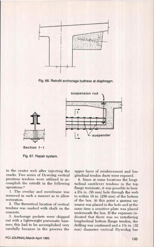
Fig. 66. Retrofit anchorage buttress at diaphragm.
suspension rod
uni.
LL. suspender
Section 1-1
Fig. 67. Repair system.
in the center web after injecting thecracks. Two series of Dywidag verticalprestress tendons were utilized to ac-complish the retrofit in the followingoperations:4
1. The overlay and membrane wasremoved in such a manner as to allowrestoration.
2. The theoretical location of verticaltendons was marked with chalk on theconcrete.
3. Anchorage pockets were chippedout with a lightweight pneumatic ham-mer; this had to he accomplished verycarefully because in the process the
upper layer of reinforcement and lon-gitudinal tendon ducts were exposed.
4. Since at some locations the longi-tudinal cantilever tendons in the topflange terminate, it was possible to borea 2' in. (56 mm) hole through the webto within 10 in. (250 mm) of the bottomof the box. At this point a gamma raysource was placed in the hole and at thesame time a sensitive plate was placedunderneath the box. If the exposure in-dicated that there was no interferinglongitudinal bottom flange tendon, thedrilling was continued and a 1 1/4 in. (32mm) diameter vertical Dywidag bar
PCI JOURNAL^March-April 1985 133

tendon was placed (Fig, 70a). Wherethere was interference from either alongitudinal top or bottom tendon, thesingle tendon was replaced by two I in.(26.5 mm) diameter Dywidag bars oneither side of the web (Fig. 70b).
Placement of retrofit shear tendons asindicated above is very satisfactory intheoretical terms but has the followingdisadvantages:'•27
In the case depicted by Fig. 70a:1. An anchorage is located near the
roadway surface and therefore is sus-
ceptible to deicing chemicals.2. Because of anchorage slip and or
anchor set losses associated with shorttendons, it is difficult to obtain a theoret-ical prestress force.
3. Boring is always a sensitive opera-tion and often impossible, especiallywhen boring the full depth of the web.
In the case depicted by Fig. 70b, theboring problem is significantly mini-mized; however, the problem of anchor-age location with respect to the roadwaysurface and losses in short tendons are
Fig. 68. Counteracting external loading.
thickened flange or rib
-w-- ^^ L
•
roug ened surface
thickened flange_...,rib
Section 1-1
Fig. 69. Repair system.
134
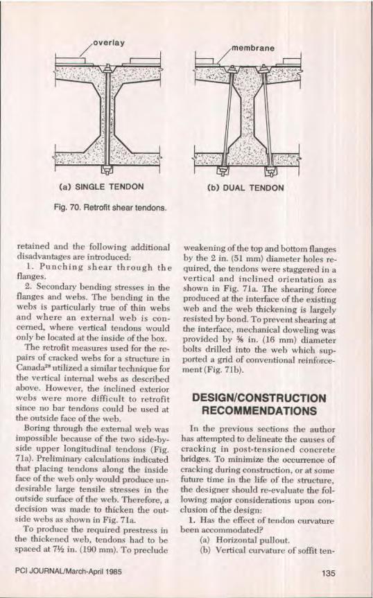
(a) SINGLE TENDON (b) DUAL TENDON
Fig. 70. Retrofit shear tendons.
retained and the following additionaldisadvantages are introduced:
I. Punching shear through theflanges.
2. Secondary bending stresses in theflanges and webs. The bending in thewebs is particularly true of thin websand where an external web is con-cerned, where vertical tendons wouldonly be located at the inside of the box.
The retrofit measures used for the re-pairs of cracked webs for a structure inCanada" utilized a similar technique forthe vertical internal webs as describedabove. However, the inclined exteriorwebs were more difficult to retrofitsince no bar tendons could be used atthe outside face of the web.
Boring through the external web wasimpossible because of the two side-by-side upper longitudinal tendons (Fig.71a). Preliminary calculations indicatedthat placing tendons along the insideface of the web only would produce un-desirable large tensile stresses in theoutside surface of the web. Therefore, adecision was made to thicken the out-side webs as shown in Fig. 71a.
To produce the required prestress inthe thickened web, tendons had to bespaced at 7 1/2 in. (19(1 mm). To preclude
weakening of the top and bottom flangesby the 2 in. (51 mm) diameter holes re-quired, the tendons were staggered in avertical and inclined orientation asshown in Fig. 7Ia. The shearing forceproduced at the interface of the existingweb and the web thickening is largelyresisted by bond. To prevent shearing atthe interface, mechanical doweling wasprovided by % in. (16 mm) diameterbolts drilled into the web which sup-ported a grid of conventional reinforce-ment (Fig. 71b).
DESIGN/CONSTRUCTIONRECOMMENDATIONS
In the previous sections the authorhas attempted to delineate the causes ofcracking in post-tensioned concretebridges. To minimize the occurrence ofcracking during construction, or at somefuture time in the life of the structure,the designer should re-evaluate the fol-lowing major considerations upon con-clusion of the design:
1. Has the effect of tendon curvaturebeen accommodated?
(a) Horizontal pullout.(I)) Vertical curvature of soffit ten-
PCI JOURNALIMarch-April 1985 135
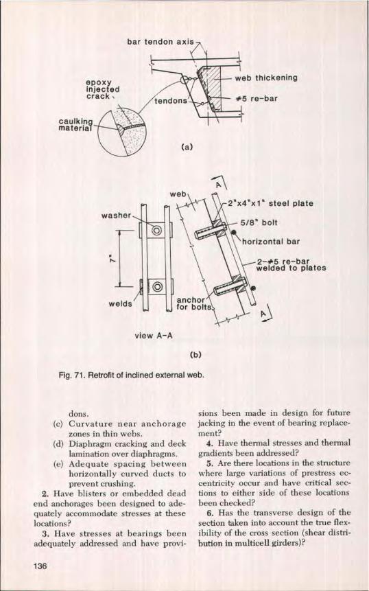
bar tendon axis
epoxy web thickeningInjectedcrack tendons +^5 re-bar
caulkingmaterial
(a)
web2"x4"x 1" steel plate
washer5/8" bolt
horizontal bar.
\ 2-#5 re-barwelded to plates
welds anchorfor bolts
view A-A
(b)
Fig. 71. Retrofit of inclined external web.
dons.(c) Curvature near anchorage
zones in thin webs.(d) Diaphragm cracking and deck
lamination over diaphragms.(e) Adequate spacing between
horizontally curved ducts toprevent crushing.
2. Have blisters or embedded deadend anchorages been designed to ade-quately accommodate stresses at theselocations?
3. Have stresses at bearings beenadequately addressed and have provi-
sions been made in design for futurejacking in the event of bearing replace-ment?
4. Have thermal stresses and thermalgradients been addressed?
5. Are there locations in the structurewhere large variations of prestress ec-centricity occur and have critical sec-tions to either side of these locationsbeen checked?
6. Has the transverse design of thesection taken into account the true flex-ibility of the cross section (shear distri-bution in rnulticell girders)?
136

It is recommended that provisions forfuture prestressing (say 10 percent of thedesign longitudinal prestress force) beprovided for in the initial design. Pro-viding anchorage bearing plates andtrumpets in the diaphragms and inter-mediate deviation saddles for futureplacement of external tendons is a veryminor cost during initial construction.To provide this capability after initialconstruction can he a very expensiveand difficult task.
During construction a number of sim-ple precautions can preclude costly timedelays and repairs.
1. Use of stiff pipe mandrels and wo , 'cbridges to preclude displacement or o:f-setting of tendons from segment to seg-ment during fabrication or casting.
2. Verify that ducts are not being"kinked" at tendon curvature locations.Use prebent heavy gauge ducts or steeltubes when curving of tendons is neces-sary.
3. Verify that adequate spacing isprovided between ducts at points ofhorizontal curvature to prevent crushingof ducts, i.e., spread the ducts as muchas possible.E"
4. Be aware of and check constructionloads to preclude overstressing andcracking i.e., stock piling of material onthe deck.
5. Immediately bring to the attentionof the Engineer any interferences be-tween ducts or ducts and reinforcementand carefully evaluate the consequencesof duct relocation or cutting or rein-forcement
6. Careful adherence to and moni-toring of concrete curing methods.Avoid temperature gradients betweensegments during match-casting opera-tions. Avoid accelerated curing."
7. Minimize or eliminate any warpingor distor -ion of segments during stor-age when the concrete is still at an earlyage.
CONCLUDING REMARKS
An attempt has been made in thispaper to document the current state-of-knowledge with regard to reasons forcracking in post-tensioned concrete boxgirder bridges. However, the reasons forcracking are so varied, complex and in-teractive that it is impossible to presenta document that is all inclusive and au-thoritative. As with any type of con-struction with any material, problemsarise that require the attention of notonly the designer, but contractors andsubcontractors as well. No matter howgood the design, if the structure is notproperly constructed, there will beproblems. Conversely, no matter howdilligent the contractor, if the designdetails are poor, problems will result.Obviously, if both the design and theconstruction are poor, problems arecompounded.
Technological progress is only ofvalue if it is measured against both pos-
itive and negative experiences. How-ever, there exists in our society a can-toes attitude toward dealing with unfa-vorable developments, errors, and dam-ages which inhibits technological prog-ress. Unfortunately, when a problem oc-curs the initial reaction is to seek out theguilty. This then leads to the situationwhereby, under direction from the legalprofession, all parties concerned are ad-vised not to discuss the problem be-cause of potential liability and litigation.
This is to some extent understandablesince none of the parties involved desireto jepoardize their rights or to incrimi-nate themselves. The disadvantage isthat it may take years before the case isresolved in the courts and in the mean-time the public safety at large may bejeopardized because the same errors orproblems are perpetuated in possiblyhundreds of additional projects. Thisimpasse requires resolution and cooper-
PCI JOURNAIJMarch-April 1985 137

ation from both the legal and engineer-ing professions.
The only way our technology can ad-vance is if problems are openly andfrankly discussed, resolved and infor-mation disseminated to the profession.
Education by dissemination of informa-tion is the only viable methodologyavailable to minimize the recurrence ofthe problem. If this is not done, we runthe risk of losing credibility with deci-sion makers and society in general.
ACKNOWLEDGMENTS
The data presented in this paper hasbeen gathered from personal experienceand from numerous and varieddocumented sources. Much of the mate-rial presented is not original. Althoughacknowledgment of all the many sourcesis not possible, full credit is given wher-ever the specific source can be identi-fied.
The author is particularly indebted to
Professor T. Y. Lin, T. Y. Lin Interna-tional; Mr. Robert C. Cassano, Califor-nia Department of Transportation; andMr. Clarence R. Yamamoto, Hawaii De-partrnent of Transportation, for materialpresented on the "Pullout of Horizon-tally Curved Tendons." In addition, theassistance of Professor Ben C. Lerwick,Jr. in obtaining several FIP documentsis appreciated.
REFERENCES1. Technical Instructions for the Inspection
and Maintenance of Highway Structures,Interim Document 32, Sub-document 2,"Box Girder or Ribbed Panel Bridges,and Similar Prestressed Concrete Struc-tures," Department of Highways andHighway Traffic, Ministry of Transpor-tation (France), October 19, 1979.
2. Bouvy, J. J . , and Foxier, J., "ProblemsEncountered in Segmental Bridges In-fluencing Precast Segmental Construc-tion," FIP Proceedings, V. 3, 1982.
3. Podolny, W., Jr., and Muller, J. M., Con-struction and Design of PrestressedConcrete Segmental Bridges, John Wiley &Sons, New York, N.Y., 1982.
4. Moreau, P., and Virlogeux, M., "LessonsFrom a Shear-Cracked Bridge," Elev-enth Congress of the International Asso-ciation for Bridge and Structural Engi-neering, Vienna, September 1-5, 1980.
5. Leonhardt, F., and Lippoth, W., "Les-sons From Damage to Prestressed Con-crete Bridges," Beton- und Stahlbeton-bau (Berlin), No- 10, October 1970.
6. Leonhardt, F., Koch, R., and Rostasy,F. S., "Suspension Reinforcement forIndirect Loading of Prestressed Con-crete Beams: Test Report and Recom-mendations," Beton- and Stahlbeton-bau (Berlin), No. 10, October 1971.
7. National Association of Australian StateRoad Authorities, NAASRA Bridge De-sign Specifications, 5th Edition, 1976,
8. American Association of State Highwayand Transportation Officials, "StandardSpecifications for Highway Bridges,"13th Edition, 1983.
9. Ontario Ministry of Transportation andCommunication, "Ontario HighwayBridge Design Code and Commentary,"1979.
10. Priestley, M. J. N., and Buckle, 1. C.,"Ambient Thermal Response of Con-crete Bridges, Bulletin 42, Road Re-search Unit, National Roads Board,Wellington, New Zealand, 1979.
11. Priestley, M. J. N., "Design of ConcreteBridges for Temperature Gradients,"ACI Journal, V. 75, No. 5, May 1978.
12. Leonhardt, F., "Prevention of Damagesin Bridges," FIP Proceedings, V. 1, 1982,
13. Leonhardt, F., Kolbe, C., and Peter, J.,"Temperature Differences EndangerPrestressed Concrete Bridges," Beton-und Stahlbetonbau (Berlin), No. 7, July1965.
14. New Zealand Ministry of Works and De-velopment, "Highway Bridge DesignBrief," CDP 701/D, Civil Division Pub-lication, Wellington, New Zealand,September 1978_
138

15. British Standard BS 5400, Steel, Con-crete and Composite Bridges, Part 1General Statement, 1978.
16. Precast Segmental Box Girder Manual,Published jointly by the PrestressedConcrete Institute and Post-TensioningInstitute, 1978.
17. Hejnic, Jiri, "Effects of TemperatureChanges on Prestressed ConcreteBridge," Presented at FIP Seventh Con-gress, New York, May 26—June 1, 1974.
18. "Proposed Recommendations for Seg-mental Construction in Prestressed Con-crete," FIP Commission—Prefabrica-tion, 3rd Draft, September 1977.
19. Stone, W. C., and Breen, J. E., "Analysisof Post-Tensioned Girder AnchorageZones," Research Report 208-1, Centerfor Transportation Research, The Uni-versity of Texas at Austin, August 1980.
20. Stone, W. C., Paes-Filho, W., and Breen,J. E., "Behavior of Post-TensionedGirder Anchorage Zones," Research Re-port 208-2, Center for Transportation Re-search, The University of Texas at Aus-tin, August 1980.
21. Stone, W. C., and Breen, J, E., "Designof Post-Tensioned Girder AnchorageZones," Research Report 208-3F, Centerfor Transportation Research, The Uni-versity of Texas at Austin, June 1981.
22. Stone, W. C., and Breen, J. E-, "Behaviorof Post-Tensioned Girder AnchorageZones," PCI JOURNAL, V. 29, No. 1.,January-February 1984, pp. 64-109.
23. Stone, W. C., and Breen, J. E., "Designof Post-Tensioned Girder AnchorageZones," PCI JOURNAL, V. 29, No. 2,March-April 1984, pp. 28-61.
24. Gerwick, Ben C., Jr., "Causes and Pre-vention of Problems in Large-Scale Pre-stressed Construction," PCI JOURNAL,V. 27, No. 3, May-June 1982, pp. 58-75.
25. Harwood, Allan C., "1-205 ColumbiaRiver Bridge—Design and ConstructionHighlights," PCI JOURNAL, V. 27, No.2, March-April 1982, pp. 56-77.
26, ACI Committee 318, "Building Code Re-quirements for Reinforced Concrete (ACI318-83)," American Concrete Institute,Detroit, Michigan, 1983.
27. Lecroq, P., and Poineau, D., "Rein-forcement of Bridges by Prestressing,"Eleventh Congress of the InternationalAssociation for Bridge and StructuralEngineering, Vienna, September 1-5,1980.
28. Dilger, W. H., and Ghali, A., "RemedialMeasures for Cracked Webs of Pre-stressed Concrete Bridges," PCI JOUR-NAL, V. 19, No. 4, July-August 1974, pp.76-85.
NOTE: Discussion of this paper is invited. Please submityour comments to PCI Headquarters by November 1, 1985.
PCI JOURNALiMarch-April 1985 139