Embed Size (px)
Citation preview

)meter
The BaBar CsI(TlElectromagnetic Calori
Jane TinslayBrunel University
3rd December 1999

Contents
❍ Introduction
❍ Physics of Electromagnetic Calorimetry
❍ Particle interactions with matter❍ Electromagnetic showers❍ Scintillation and radiation damage processes❍ Energy resolution
❍ The BaBar Calorimeter
❍ Design and construction❍ Reconstruction❍ Calibration❍ Current performance
❍ Conclusions

primary particle is
s with the
nto scintillation
l.
all-NaI(Tl),KTev-O4.
Introduction
✴ A device which measures the total energy deposited by a called a calorimeter.
✴ The primary particles energy is degraded by interaction calorimeter material.
✴ A scintillating crystal calorimeter converts this energy i light.
✴ The scintillation light is converted to an electrical signa
✴ Electrical signal proportional to primary energy.
✴ Other experiments using crystal calorimeters- Crystal BCsI, L3-BGO, CLEO, BELLE, BaBar-CsI(Tl) ,CMS -PbW

5.5 charged tracks.
Why does BaBar need a calorimeter ?
✴ Generic B decays contain an average of 5.5 photons and
✴ ~50% of photons < 200 MeV.
✴ Need excellent energy, positionresolution in order to reconstructπ0s.
✴ Need excellent photon detection efficiencies down to low energies
(20 MeV).
✴ Charged, neutral PID.
✴ Crystal calorimeter most suited - best energy resolution

tter
dEdX----
EX0----≅
Particle Interactions With MaElectron/Positron Processes
✴ At low energies, ionisationdominates.
✴ At high energies, bremsstrahlungdominates.
✴ Radiation length,
Nucleus
e-
e-
γBremsstra hlungMean distance over which all
but 1/e of energy is lostdue to bremsstrahlung.
X0716.4gcm
2–A
Z Z 1+( ) 287 Z( )⁄( )ln-----------------------------------------------------------=

ionisation is the
gth is equal to the
✴ Critical energy, Ec = energy at which the energy loss by same as the loss by radiation.
OR
✴ Ec = energy at which the ionisation loss per radiation len electron energy.
Ec800MeVZ 1.2+
----------------------=
Ec610MeVZ 1.4+
----------------------=

Nucleus
Pair Product ion
γ e-
e+
Nucleus
γ
e-
γCompton Scatter ing
Nucleus
γ
e-
Photoelectric effect
Photon Processes

e MeV range, cross reaches a mini-o low energy pho-ay travel a long wayinteracting.
I 0eµt–( )
=
µ 1λ---=
✴ Mean free path at high energies
CsI
λ 97---X0=
✴ In thsectionmum stons mbefore
I

tromagnetic shower
produced by the
e-
γ
e+
e-
γ
e-
e-
γ
e-
e+ e+
γ
2 3
Electromagnetic showers
✴ When a photon/electron/positron enters a crystal an elec is initiated.
✴ A cascade of secondary photons, electrons and positrons particle interactions described previously.
✴ Average shower properties described by simple model.
✴ Define the scale variables:
e-γ
e-
1X0 0
tx
X0-------=
yE0Ec-------=

E0Ec------- y≈
)----
After t generations...
N t( ) 2t
=
E t( )E0
2t
-------=
L23--- N t( ) td
0
tmax∫ ≈=
Number of particles present
Average energy of a shower particle
tmax
E0 Ec⁄(ln
2ln-------------------------=Shower Maximum
Total track lengths of all chargedparticles

m Monte Carlo
i
tainty in the
✴ An over simplified model - more accurate predictions frotechniques.
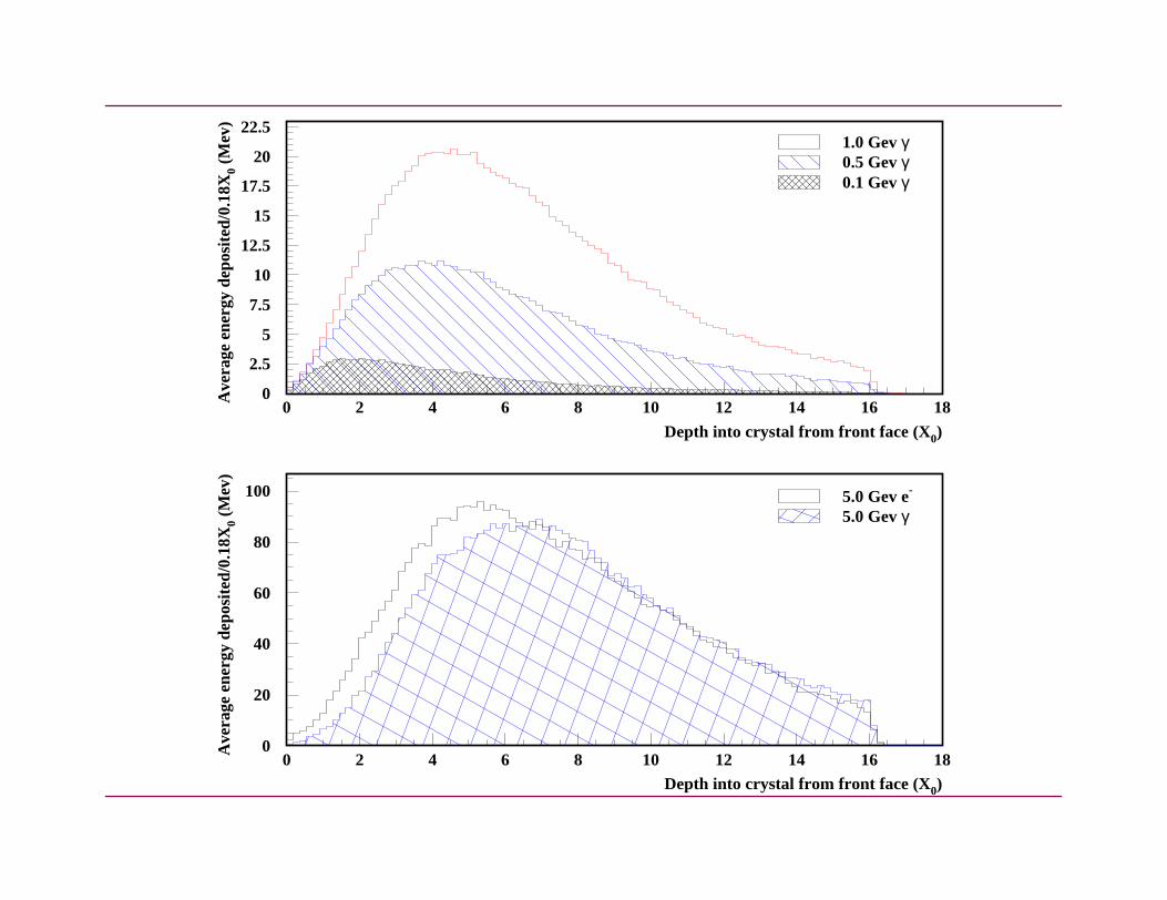
Ed
td------ E0
bt( )a 1–e
bt–
Γ a( )---------------------------------=
tmax a 1–( ) b⁄ yln C+= =
Longitudinal profile
Where Ce=-0.5, Cγ=+0.5, b =0.5
✴ Photon induced showers are longer because of the uncer position of the first pair production.

1X0.
far depending on
l size to scale withtal dimensions.
er with a radius of
Lateral Profile
✴ Exponential profile.
✴ Up to tmax shower, contained in a cylinder with radius <
✴ Soft photons found near the end of shower - may travel cross sections.
✴ After tmax, multiple scattering of electrons causes latera the Moliere radius - determines optimal transverse crys
✴ Roughly 95% of a shower is contained laterally in a cylind 2Rm
Rm
X0 21.2Mev×
Ec------------------------------------=
16 18
1.0 Gev γ0.5 Gev γ0.1 Gev γ
om front face (X0)
16 18
5.0 Gev e-
5.0 Gev γ
om front face (X0)
0
2.5
5
7.5
10
12.5
15
17.5
20
22.5
0 2 4 6 8 10 12 14
Depth into crystal fr
Ave
rage
ene
rgy
depo
site
d/0.
18X 0 (M
ev)
0
20
40
60
80
100
0 2 4 6 8 10 12 14Depth into crystal fr
Ave
rage
ene
rgy
depo
site
d/0.
18X 0 (M
ev)

Damage
ermined by
energy levels -
rgy levelsity
CsI(Tl) Scintillation and RadiationMechanisms
Scintillation Mechanism
✴ CsI(Tl) is an inorganic scintillator.
✴ Scintillation mechanism depends on energy states - det the structure of the crystal lattice.
✴ Well defined valence and conduction bands.
✴ Impurities, called activators (Thalium) added to modify increase the probablility and λ of scintillation light.
Exciton
Valence band
Conduction band
Hole
Electron
Modified enedue to impur
Exciton band

previous diagram).
- Impurity is in aded to excite it to a
✴ Fluorescent light with a relatively short decay time (see
✴ Phosphorescent light (afterglow) with a long decay time metastable state. Extra energy (eg, thermal energy) nee level where it can return to ground state.
✴ Issues:
Transparent to own radiation Decay time Radiation hardness Light Yield Wavelength of scintillation light Radiation length Ease of manufacture Cost

stal response.
ism.
absorption bands.
Radiation Damage✴ All crystals suffer from radiation damage -change in cry
✴ Not thought to be a damage to the scintillation mechan
✴ The formation of colour centres in the crystal produces

placed from itsctron can drop,
long enough,ut.
manufacture.
e energy resolution.
r leakage’ effect.
✴ Colour centres are formed when an impurity atom is dis lattice position by ionising radiation, into which an ele causing absorption bands.
✴ Results in an overall loss in light output.
✴ If the photon attenuation length in a given crystal isn’t radiation damage will produce a non-uniform light outp
✴ Every crystal is different - impurities introduced during
✴ Crystal non-uniformity introduces a constant term to th
✴ Non-uniformity isn’t always bad - the ‘compensation fo

calorimeter will
nergy
E
BE----
2C
2+ +
Energy Resolution
✴ A beam of mono-energetic photons incident fired into ahave a spread in measured energy.
✴ Energy resolution :σEE
-------
E
σ✴ Contributions:
Fluctuations in scintillation photons stats Fluctuations in photo-electron stats Noise-coherent+incoherent Leakage fluctuations Calibration Front material (efficiency) backgrounds non-uniform light collection
σE----
2 A
E--------
2=

stal wrappings, two
3mr
E----------
22mr
2+
A = Shower+readout fluctuationsB = NoiseC = Calibration, leakage, non-uniformity, dead material
BaBar
✴ Achieved through high crystal light yield, reflective cryphotodiodes, very low electronic noise.
σE----
2 0.01
E4----------
2
0.0122
+=
σθ( )2 =
Angular resolution
✴ Determined by the transverse crystalsize and average distance to the interactionpoint.

The BaBar CalorimeterDesign and Construction

with 120 crystals inφ.3*7 crystals.ow - 6 crystals inθ)tric tonnes.
ϑ( )os 0.715≤ (CM)
180.9 cm
e+e–
91 cm15.8°
140.8°
IP26.9°
112.7 cm
EMC locatedasymetricallyabout interaction point.Non-projective crystal geometry by15-45mr in θ - minimise lost photons.
0.775– ϑ( )cos 0.962≤ ≤
Barrel :
5760 crystals.48 θ rows, each 280 modules of (except for last rWeighs 23.5 me
0.916– c≤
(lab)
(CM)0.916– ϑ( )cos 0.895≤ ≤
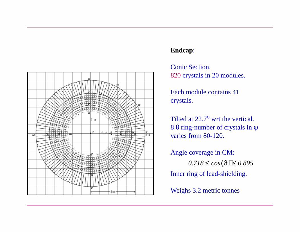
n.n 20 modules.
contains 41
wrt the vertical.er of crystals inφ
0-120.
ge in CM:
lead-shielding.
etric tonnes
ϑ( )cos 0.895≤
Endcap:
Conic Sectio820 crystals i
Each modulecrystals.
Tilted at 22.7o
8 θ ring-numbvaries from 8
Angle covera
Inner ring of
Weighs 3.2 m
0.718≤

the back barrel.
nd side faces),
plifiers.
ystal (negligible).
Crystals:
✴ Trapezoidal in shape.
✴ Range in length from 17.5 X0 in the EndCap, to 16 X0 in
✴ Typical front face dimensions 4.7*4.7 cm2
✴ Typical back face dimensions 6.0*6.0 cm2
✴ Tolerances: 250 µm transversely, 1mm longitudinally.
✴ Crystal wrappings: two 150 µm layers of Tyvek (front a one layer of 30 µm aluminium foil.
✴ Read out by two silicon PIN diodes, connected to pream
✴ Implements two independent electronics chains - reliability + signal/noise.
✴ With digital filtering incoherent noise = 150 KeV per cr
✴ Noise dominated by beam backgrounds.

ing/polishing
✴ Crystals are tuned for uniform light collection - roughen surface.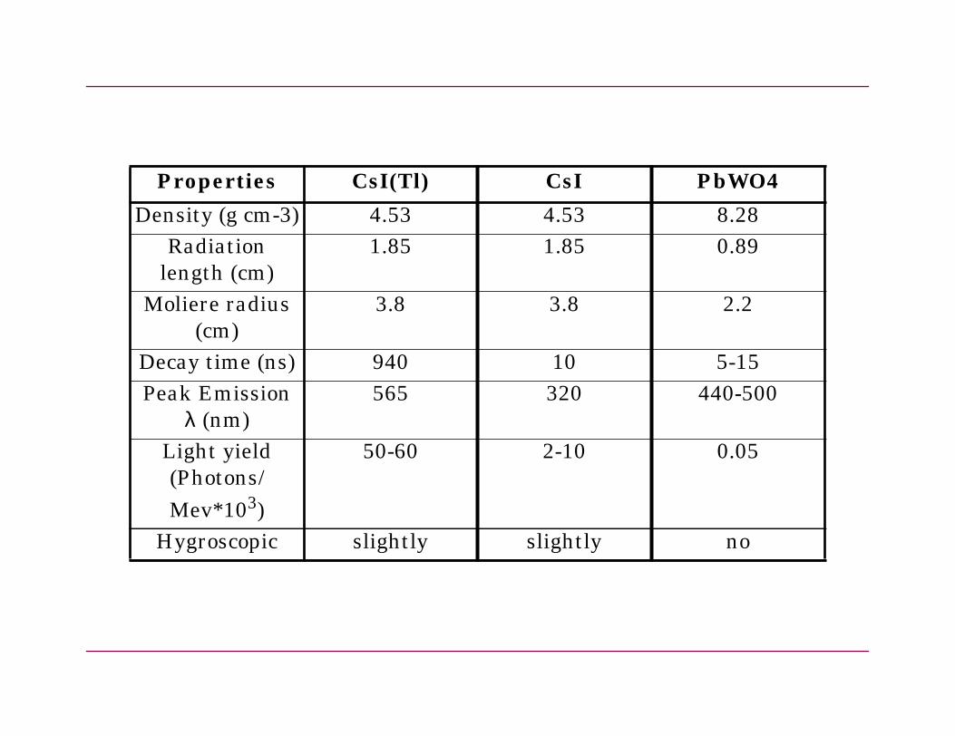
PbWO4
8.280.89
2.2
5-15440-500
0.05
no
Properties CsI(Tl) CsI
Density (g cm-3) 4.53 4.53Radiation
length (cm)1.85 1.85
Moliere radius(cm)
3.8 3.8
Decay time (ns) 940 10Peak Emission
λ (nm)565 320
Light yield(Photons/Mev*103)
50-60 2-10
Hygroscopic slightly slightly

uorocarbon whichng in 6.13 Mev
stals.
nearity.
re dose.
Features
Radioactive source system
✴ Thin tubes on the front face of the calorimeter carry a fl has been excited by neutron irradiation - decays resulti photons.
✴ Used as a calibration and monitoring tool.
Light pulser system
✴ Xenon flash lamps feed light onto the rear face of all cry
✴ Used as a monitoring and diagnostic tool - electronics li
RadFETs
✴ 56 in barrel, 60 in End Cap - small devices which measu

Modules made from 300 µm CFC,and supported from the rear byan aluminium strongback.Mounted in an aluminium sup-port cylinder-supported off coil.Cooling and cables located at the back of the modules.


20 MeV.
k for local maxima.
ed under a
Reconstruction
✴ Digis->Clusters->Bumps->Cands
✴ Digis: Crystals with >1 MeV (TDR=0.5 MeV).
✴ Cluster: Collection of adjacent digis. Summed energy >
✴ Bump: Split each cluster up into one or more bumps-loo
✴ Cand: Energy+position corrected bump or cluster, select particular particle hypothesis.
PID
✴ Charged: e-, µ, π − shower shapes, E/P
✴ Neutral: γ, merged π0, K0L - shower shapes

ree calibrations:
onse using a charge
an individual crys-
de out of clusters ofy due to clustering,
anges - eg, radiation
h should
Calibration
✴ Scintillation light -> final particle energy depends on th
✴ Electronics calibration: Linearises the electronics respinjection system.
✴ Inter-Crystal calibration: Determines the response of tal. Calibrates to the deposited energy. Time dependent.
✴ Cluster calibration: Applied to candidate particles macrystals. Sets the final energy scale. Corrects for lost energleakage. Time independent.
✴ Monitoring - light pulser + calibration methods track chdamage.
Inter-Crystal Calibration
✴ Different response depending on incident energies whic (if the crystals are reasonably uniform) be small.
✴ Fixes calibration points along a calibration curve.

Energy
Techniques:
✴ Bhabhas✴ High energy point (3->9 GeV)✴ Well known topology.✴ High rate (200 hits/crystal = ~8 hours
data taking at nominal luminosity)
✴ Source✴ Low energy point (6.13 MeV)✴ Fast (doesn’t depend on luminosity !).✴ Has seen changes in crystal response.
✴ Radiative Bhabhas - intermediateenergies.
cons
tant
n - data.
Cluster Calibration
✴ Theta, particle type dependent.
✴ MC derived correction.
✴ Pi0Calibrator - shifts pi0 mass peak to correct positio
✴ Polynomial derived correction.
✴ Should be relatively stable over time.

ht pulser).
wer supplies,
eV.
dose of ~50 rads int is 10 krad over 10
Current Status
✴ Problems at startup:✴ Coherent noise.✴ Electronics non-linearity (diagnosed by lig
= High digi cut = worse resolution.
✴ Major improvements with coherent noise-torroids on po oscillating capacitor removed.
✴ Digi cut now at 1 MeV (was at 5 MeV), TDR aim is 0.5 M
✴ Pi0 cluster calibrator derived from data implimented.
✴ Beam backgrounds not as bad as expected - accumulated hottest crystals (improved vacuum, collimators). Budge years
✴ 10% difference in source and bhabha constants.

E measured / E expected1 1.1 1.2 1.3 1.4 1.5
BABAR
(fwd brl)
E measured / E expected deposited0.6 0.7 0.8 0.9 1 1.1 1.2 1.3
En
trie
s/B
in
0
200
400
600
800
1000
1200
1400
1600
1800Constant = 1674
Mean = 1.016
Sigma = 0.02214
EMC Bhabha Clusters
Forward Barrel
BaBarConstant = 1674
Mean = 1.016
Sigma = 0.02214
0.5 0.6 0.7 0.8 0.9
En
trie
s
0
500
1000
1500
2000
2500Constant = 2227 +- 14.12
Mean = 0.9963 +- 0.0001326
Sigma = 0.02441 +- 4.441e-05
Constant = 2227 +- 14.12
Mean = 0.9963 +- 0.0001326
Sigma = 0.02441 +- 4.441e-05
MC E/E_expected

mγγ (GeV)0.5
ar
.2 MeV
MeV
0 0.1 0.2 0.3 0.4
Ent
ries
0
500
1000
1500
2000
2500
3000
3500
π0 Mass E γγ > 500 MeV
BaB
π0-mass = 134
π0-width = 7.7
(MC gives 4-6 MeV width)
y the
r performance
Conclusions
✴ CsI(Tl) Crystal calorimeter should deliver the necessar photon/electron energy resolution required.
✴ Detector is functioning - big improvements with detecto - still things to understand...

lmut Marsiske)
5, lectures by Rich-
ernow
.
Bibliography
SLUO Lecture Series - Lectures 13, 14 (Jim Brau), 15 (He
PDG - Passage of particles through matter
Techniques and Concepts of High Energy Physics VI -p.32ard Wigmans.
BaBar Physics Book, TDR
Introduction to Experimental Particle Physics - Richard F
Radiation Damage: Papers by Ren-yuan Zhu, H. Chowdry