Embed Size (px)
Citation preview

1
The AUTOSAR Way of Model-Based Engineering ofAutomotive Systems
Heiko DörrInternational Conference on Graph TransformationLeicester, 12.09.2008
--
Fol
ie 2
Explore potentials of the application
of graph transformation in
an AUTOSAR
development
Explore potentials of the application
of graph transformation in
an AUTOSAR
development
Purpose of the Presentation.
Long history of graph transformation
� Sound body of theory
� Several areas of application
� Tool-support available to handle larger models
Identification of research and
development topics
Identification of research and
development topics
Future model-basedengineering of
automotive systems will use AUTOSAR

2
--
Fol
ie 3
Content.
Methodology
AUTOSAR
Standardization
AUTOSAR
StandardizationMethodology of
System Development
Methodology of
System Development
2 3
Automotive System
Engineering
Automotive System
Engineering
1
R&D TopicsR&D Topics
4
ApplicationInterfaces
Methodology
Architecture
Tool supporting deploymentof SW components
ECU I ECU II
AU
TO
SA
RS
W-C
1
AU
TO
SA
R
SW
-C2
AU
TO
SA
RS
W-C
3
ECU m
AU
TO
SA
RS
W-C
n
RTE
Basic Software
RTE
Basic Software
RTE
Basic Software
...
Gateway
SW-C
Virtual Functional Bus
AU
TO
SA
RS
W-C1
AU
TO
SA
RS
W-C
2
AU
TO
SA
RS
W-C
3
AU
TO
SA
RS
W-C
n...
SW-C
Description
SW-C
Description
SW-C
Description Description
ECU
DescriptionsSystem Constraint
Description
4
Automotive Systems and SW Engineering

3
5
Automotive Open System ArchitectureCooperate on standards – compete on implementation
Driver assistance
Driving dynamics
Safety functions(active/passive)
Comfort functions
Resource efficiency
Vehicle familymanagement
Non functionallegal requirements
6
OEM f
Supplier B
�Chassis
�Safety
�Telematics
�Multimedia
Supplier A
� Chassis
� Safety
� Body/Comfort
� Multimedia
Supplier C
�Body/Comfort
�Powertrain
�Telematics
�Multimedia
Exchangeabilitybetween
supplier‘ssolutions
Exchangeabilitybetween vehicle
platforms
Exchangeabilitybetween
manufacturer‘sapplications
Platform d.nPlatform d.2Platform d.1
Platform e.nPlatform e.2Platform e.1
Platform f.nPlatform f.2Platform f.1
Platform c.nPlatform c.2Platform c.1Platform a.n
Platform a.2Platform a.1
OEM e
OEM a
Platform b.nPlatform b.2Platform b.1
OEM b
OEM d
OEM c
AUTOSAR Managing Complexity by Exchangeability and Reuse of Software Components

4
--
Fol
ie 7
Model-based Development.General Task.
Vehicle
Driver
Demand
Sensors
Actuators
Plant
Environment
MeasurementControl
W
R
U
W*
Z
Y
X
MbE-Slides by M. Conrad, Abb: Schäuffele/Zurawka: Automotive Software Engineering; Foto: www.bba-reman.com/ images/ecu.jpg
Control Unit
Micro-controller
Input Decoder
Power / Communi
cation Control
W
R
WINT UUINT
RINT
(Electronic) Control Unit
U
W
R
--
Fol
ie 8
Micro controller
UDIS D/Aconverter
Model-based Development.Paradigm Shift.
SoftwareA/Dconverter
WINT
RINT
WDIS
UINT
RDISA/Dconverter
Software componentfor computation of control functions
Idea
Document based development process
Model based development
process
MbE-Slides by M. Conrad

5
--
Fol
ie 9
Micro controller
UDIS D/Aconverter
SoftwareA/Dconverter
WINT
RINT
WDIS
UINT
RDISA/Dconverter
Model-based Development.Evolution of Models.
Idea
Requirements /Behavioral model of system
Physical model
Implementation model
Autocode
�*.h�*.c
t
MbE-Slides by M. Conrad
10
AUTOSAR RTE
AUTOSAR Int.
SwitchEvent
Standardized Interface
Microcontroller Abstraction
Std. AUTOSARInterface
Services
Std. Interface
ECUAbstraction
AUTOSARInterface
Std. Interface
ComplexDeviceDrivers
AUTOSARInterface
StandardizedInterface
Communi-cation
Std. Interface
StandardizedInterface
OperatingSystem
DIO
check_switch ()
AUTOSAR Interface
LightRequest
AUTOSAR Interface
Front-Light Manager
get_keyposition()
AUTOSAR Interface
Headlight
set_current (…)
CAN Driver
switch_event(event)
switch_event
(event)
request_light
(type, mode)
request_light(type, mode)
set_light(type, mode)
set_light(type, mode)
PWM
Sta
nd
ard
ize
dIn
terfa
ce
Use case ‘Front-Light Management’
Operating System
Communication Control
Memory Management
Drivers
Hardware
ECU1

6
11
Standardized Interface
Microcontroller Abstraction
AUTOSAR RTE
AUTOSAR Int.
SwitchEvent
Std. AUTOSARInterface
Services
Std. Interface
ECUAbstraction
AUTOSARInterface
Std. Interface
ComplexDeviceDrivers
AUTOSARInterface
StandardizedInterface
Communi-cation
Std. Interface
StandardizedInterface
OperatingSystem
DIO
check_switch ()
AUTOSAR Interface
LightRequest
AUTOSAR Interface
Front-Light Manager
get_keyposition()
AUTOSAR Interface
Headlight
set_current (…)
CAN Driver
switch_event(even
t)switch_event
(event)
request_light
(type, mode)
request_light(type, mode)
set_light(type, mode)
set_light(type, mode)
PWM
Sta
nd
ard
ize
dIn
terfa
ce
AUTOSAR Interface
Xenonlight
set_light(type, mode)
set_current (…)
DIO
Use case ‘Front-Light Management’ Exchange of type of front-light
Operating System
Communication Control
Memory Management
Drivers
Hardware
ECU2
12
Standardized Interface
Microcontroller Abstraction
ECU-Hardware
AUTOSAR RTE
Std. AUTOSARInterface
Services
Std. Interface
ECUAbstraction
AUTOSARInterface
Std. Interface
ComplexDeviceDrivers
AUTOSARInterface
StandardizedInterface
Communi-cation
Std. Interface
StandardizedInterface
OperatingSystem
DIO CAN DriverPWM
Sta
nd
ard
ize
dIn
terfa
ce
DIO
Distribution on ECUs
AUTOSAR Int.
SwitchEvent
check_switch ()
AUTOSAR Int.
SwitchEvent
switch_event
(event)
AUTOSAR Interface
LightRequest
AUTOSAR Interface
LightRequest
switch_event(even
t)request_light
(type, mode)
AUTOSAR Interface
Front-Light Manager
get_keyposition()
set_light(type, mode)
AUTOSAR Interface
Front-Light Manager
request_light(type, mode)
set_light(type, mode)
AUTOSAR Interface
Xenonlight
set_current (…)
set_light(type, mode)

7
13
Use case ‘Front-Light Management’ – Multiple ECUs
CAN Bus
ECU-Hardware
AUTOSAR RTE
Standardized Interface
Microcontroller Abstraction
ECUAbstraction
AUTOSARInterface
Std. Interface
StandardizedInterface
Communi-cation
Std. Interface
CAN Driver PWM
AUTOSAR Interface
Xenonlight
set_light(type, mode)
set_current (…)
ECU-Hardware
AUTOSAR RTE
AUTOSAR Int.
SwitchEvent
Standardized Interface
Microcontroller Abstraction
Std. AUTOSARInterface
Services
Std. Interface
ECUAbstraction
AUTOSARInterface
Std. Interface
StandardizedInterface
Communi-cation
Std. Interface
DIO
check_switch ()
AUTOSAR Interface
LightRequest
switch_event(event)
switch_event
(event)
request_light
(type, mode)
AUTOSAR Interface
Front-Light Manager
get_keyposition()
request_light(type, mode)
set_light(type, mode)
Microcontroller Abstraction
Standardized Interface
StandardizedInterface
Communi-cation
Std. Interface
CAN Driver
ECU-Hardware
AUTOSAR RTE
CAN Driver
Operating System
Communication Control
Memory Management
Drivers
Hardware
ECU3
Operating System
Communication Cont.
Memory Management
Drivers
Hardware
ECU4
Operating System
Communication Cont.
Memory Management
Drivers
Hardware
ECU5
14
AUTOSAR Standardization
8
15
67 Associate Member
52 Premium Member
GeneralOEM
GenericTier 1
StandardSoftware
Tools andServices
Semi-conductors
Up-to-date status see: http://www.autosar.org
9 Core Partner
AUTOSAR – Core Partners and MembersStatus: 13th March 2008
6 Development Member
16
ApplicationInterfaces
Methodology
Architecture
� Implementation and standardization of basic system functions as an OEM wide “Standard Core“ solution
� Scalability to different vehicle and platform variants
� Transferability of functions throughout network
� Integration of functional modules from multiple suppliers
� Maintainability throughout the whole “Product Life Cycle“
� Increased use of “Commercial off the shelf hardware“
� Software updatesand upgrades over vehicle lifetime
� Consideration of availability and safetyrequirements
AUTOSAR Project Objectives and Main Working Topics

9
17
Application
InterfacesMethodology
Architecture
� Methodology:Exchange formats or description templates to enable a seamless configuration process of the basic software stack and the integration of application software in ECUs and it includes even the methodology how to use this framework.
Application
InterfacesMethodology
Architecture
� Application Interfaces:Specification of interfaces of typical automotive applications from all domains in terms of syntax and semantics, which should serve as a standard for application software.
Application
InterfacesMethodology
Architecture
� Architecture:Software architecture including a complete basic or environmental software stack for ECUs – the so called AUTOSAR Basic Software – as an integration platform for hardware independent software applications.
AUTOSAR Main Working Topics
18
Main Concepts: Architecture� Basic Software modules� Run time environment and communication

10
19
AUTOSAR ECU Software Architecture
Application Software (ASW)
Standardization of interfaces
Objectives: Basic SW: Decoupling of Hardware and Application SoftwareApplication SW: Relocation / Reuse of SW-Components between ECUs
Basic Software (BSW) +RTE
Standardization ofinterfaces and behavior
Not standardized in AUTOSAR
20
AUTOSAR Runtime Environment (RTE)
Application Layer
Microcontroller
AD
C
DIO
CC
U
PW
M
LIN
CA
N
SP
I
EE
PR
OM
FLA
SH
WD
T
GP
T
Ext. B
US
MC
U
Pow
er &
Clock U
nit
µC
e.g. CC
U
e.g. PC
P
e.g. TP
U
FlexR
ay
SC
I
I/O Drivers
PO
RT
Driver
AD
C D
river
DIO
Driver
PW
M D
river
ICU
Driver
Microcontroller Drivers
Watchdog D
river
MC
U D
river
GP
T D
river
Communication Drivers
CA
N D
river
LIN D
river
SP
I Handler D
river
Memory Drivers
RA
M T
est
internal EE
PR
OM
D
river
internal Flash D
river
Communication Services
Generic NM Interf.
FlexR
ay NM
FlexRayTP
DCMDiagnostic
Com.Manager
IPDU Multi-plexer
Communication Hardware Abstraction
Memory Services
NVRAM Manager
CR
C Lib
Flash C
heck
System Services
Function Inhibition M
anager FIM
Watchdog M
anager
Developm
ent Error
Tracer
Diagnostic E
vent M
anager DE
M
AU
TO
SA
R O
S
I/O Hardware Abstraction
Memory Hardware Abstraction
Memory Abstraction Interface
Onboard Device Abstraction
External Watchdog
Driver
CAN NM
CAN TP
Ext. Flash Driver
Flash EEPROM Emulation
FR
Driver
LIN Interface
Ext. C
AN
D
river
CAN Interface
CA
N transc
Driver
Ext. F
R
Driver
FR Interface
FR
transcD
riverExt. EEPROM
Driver
EEPROM Abstraction
Watchdog Interface
PDU Router
LIN TP
AUTOSAR COM
LIN C
omm
unication S
tack
BS
W S
cheduler
Com
munication
Manager
I/O Hardware Abstraction
AUTOSAR Basic Software Modules
CANSM
LINSM
FRSM
EC
U S
tate Man
ager

11
21
� Ports implement the interface according to the communication paradigm (here client-server based).
� Ports are the interaction points of a component.
� The communication is channeled via the RTE.
� The communication layer in the basic software is encapsulated and not visible at the application layer.
Appli-
cation
SW-C
A
RTE
BSW
ECU I
Appli-
cation
SW-C
B
RTE
BSW
ECU II
Appli-
cation
SW-C
C
VFB
Sensor
Communication Bus
Communication Path
Hardware
AUTOSARInfrastructure
Ports
Application
Intra- and Inter-ECU Communication
22
AUTOSAR Architecture – Conclusion
AUTOSAR harmonizes already existing basic software solutions and
closes gaps for a seamless basic software architecture.1
The decomposition of the AUTOSAR layered architecture into some 40 modules has proven to be functional and complete.
3
AUTOSAR aims at finding the best solution for each requirement and
not finding the highest common multiple.2

12
23
Main Concepts: Application Interfaces� Standardization approach� Current stage of standardization
24
ActuatorSoftware
Component
ApplicationSoftware
Component
SensorSoftware
Component
ApplicationSoftware
Component
..............
AUTOSARSoftware
ECU-Hardware
AUTOSAR Runtime Environment (RTE)
Basic Software Micro-controller
Abstraction
StandardizedAUTOSARInterface
ServicesECU
Abstraction
AUTOSARInterface
ComplexDeviceDrivers
AUTOSARInterface
Communi-cation
OperatingSystem
StandardizedInterface
StandardizedInterface
StandardizedInterface
StandardizedInterface
StandardizedInterface
StandardizedInterface
Sta
nd
ard
ize
dIn
terfa
ce
Application Layer
AUTOSARInterface
AUTOSARInterface
AUTOSARInterface
AUTOSARInterface
AUTOSARInterface
AUTOSARInterface
AUTOSARInterface
AUTOSARInterface
Semantics of Interfaces: � Physical properties, units, etc.� Supporting re-use across product lines� In scope of AUTOSAR work packages specifying application
interfaces
Syntax of Interfaces: � Meta-model, Software Component Template� Supporting transferability within the network
AUTOSAR Application Interfaces

13
25
To ease the re-use of software components across several OEMs,AUTOSAR proceeds on the standardization of the application interfaces agreed among the partners.
ESP
SW-Component
ESP
SW-Component2nd Yaw
Rate Controller
2nd YawRate Controller
Brake ActuatorBrake Actuator
Information signalsfrom other functions / domains
ESP-SensorsESP-Sensors
Ínterface of ESP and external yaw rate controller
Standard Signals from ESP
VehicleLongitudinal
Controller
VehicleLongitudinal
Controller
Command signals to other functions / domains
Interface of ESP and VLC
Base Sensor Signals
System-level BrakeActuator Interface
I 1
I 2
I 6
I 7
I 3
I 5
I 4
ESP
SW-Component
ESP
SW-Component2nd Yaw
Rate Controller
2nd YawRate Controller
Brake ActuatorBrake Actuator
Information signalsfrom other functions / domains
ESP-SensorsESP-Sensors
Ínterface of ESP and external yaw rate controller
Standard Signals from ESP
VehicleLongitudinal
Controller
VehicleLongitudinal
Controller
Command signals to other functions / domains
Interface of ESP and VLC
Base Sensor Signals
System-level BrakeActuator Interface
I 1
I 2
I 6
I 7
I 3
I 5
I 4
Standardized application interfaces on system level(ESP-system, chassis domain)
RollRateBaseData Type Name
…
LongAccBaseData Type Name
…
This data element can also be used to instantiate a redundant sensor interface.Range might have to be extended for future applications (passive safety).
Remarks
0Physical Offset
-32768..+32767Integer Range
S16Data Type
….…
rad/secUnit
-2,8595..+2,8594Physical Range
Yaw rate measured along vehicle z- axis (i.e. compensated for orientation). Coordinate system according to ISO 8855
Description
YawRateBaseData Type Name
Example
26
Major task: Conflict Resolution – Example Vehicle Speed
Body Domain
CentralLockingMaster
InteriorLight
Powertrain Domain
DriverReq
Chassis Domain
CentralLockingMaster
ActualVehicleSpeed
ActualVehicleSpeed
DataElementName DataTypeActualVehicleSpeed VehicleSpeed
DataElementName DataTypevalue t_VehiculeSpeed
?VehicleSpeed
Min Bit size; Res; phys low; phys up; UnitUint12 0.1 0.0 0.0 403.4 km/h
Min Bit; size; Res; phys low; phys up; UnitUint16 0.00781 0 0 511.992 km/h
ESP ACCSSMEPBVLC
SteeringSuspension
…
VehicleLongSpeed DataElementName DataTypeVehicleLongSpeed VehicleLongitudinalSpeed
Min Bit; size; Res; phys low; phys up; Unit?? ?? ?? ?? ?? ??
OK
OK
?

14
27
AUTOSAR Application Interfaces – Conclusion
For several domains a subset of application interfaces has been
standardized to agreed levels.1
It is a challenge to align standardization with the pace of application
development. 2
28
Main Concepts: Methodology� Overall methodology� Structure of configuration information� System Design – Implementation Process

15
29
Following the AUTOSAR Methodology, the E/E architecture is derived from the formal description of software and hardware components.
Tool supporting deployment
of SW components
ECU I ECU II
AU
TO
SA
R
SW
-C
1
AU
TO
SA
R
SW
-C
2
AU
TO
SA
R
SW
-C
3
ECU m
AU
TO
SA
R
SW
-C
n
RTE
Basic Software
RTE
Basic Software
RTE
Basic Software
...
Gateway
SW-C
Virtual Functional Bus
AU
TO
SA
R
SW
-C
1
AU
TO
SA
R
SW
-C
2
AU
TO
SA
R
SW
-C
3
AU
TO
SA
R
SW
-C
n...
SW-C
Description
SW-C
Description
SW-C
Description Description
ECU
DescriptionsSystem Constraint
Description
� Functional software is described formally in terms of “Software Components” (SW-C).
� Using “Software Component Descriptions“ as input, the „Virtual Functional Bus“ validates the interaction of all components and interfaces before software implementation.
� Mapping of “Software Components” to ECUs and configuration of basic software.
� The AUTOSAR Methodology supports the generation of an E/E architecture.
30
AUTOSAR MethodologyDerive E/E architecture from formal descriptions of soft- and hardware components
Virtual Functional Bus
AU
TO
SA
RS
W-C
1
AU
TO
SA
RS
W-C
2
AU
TO
SA
RS
W-C
3
AU
TO
SA
RS
W-C
n...
ECU m
AU
TO
SA
R
SW
-C
n
RTE
Basic
Software
...
VFB view
Mapping
System Constraint
Description
ECU
Descriptions
Tool supporting deploymentof SW components
Gateway
SW-CDescription
SW-CDescription
SW-CDescription
SW-CDescription
ECU II
AU
TO
SA
R
SW
-C
2
RTE
Basic
Software
ECU I
AU
TO
SA
R
SW
-C
1
RTE
Basic
Software
AU
TO
SA
R
SW
-C
3
Standardized Basic Software (BSW) architecture, detailed specifications for implementation and configuration of BSW
Standardized description templates for application software components
(interfaces and BSW requirements)
Tools for - support of component mapping - generation of RTE, i.e. inter- and intra ECU communication
Standardized exchange formats and methodology for component, ECU, and system level

16
31
SW-Component Description
SW-Component Description
SW-Component Description
SW-Component Description
SW-Component Description
To configure the system, input descriptions of all software components, ECU resources and system constraints are necessary.
ECU Resource Description
ECU Resource Description
ECU Resource Description
LightSourceSetting
BlinkInputModule
BlinkMaster
LightActuatorsControl
SwitchEvalBlinkInputModule
BlinkMaster
LightActuatorsControl
SwitchEval
LightSourceSetting
ECUs Software Components
BC-HBC-V
SMLS
LM-L LM-R
CAN
LIN
System
Description
Supported protocols:CAN, LIN, FlexRay
Example
32
The system configuration maps software components to ECUs and links interface connections to bus signals.
System Configuration
LightSourceSetting
BlinkInputModule
BlinkMaster
LightActuatorsControl
SwitchEval
SWCMappingDefs
BlinkInput
Module
BlinkMaster
Comm.Matrix for BodyCAN
…FrameInstance BlinkRequest
SignalBS1SignalBS2
DataMappingDefs
SignalBS3
BlinkRequest
Example

17
33
AUTOSAR – System Design – Implementation Process
SW Component
SW executables for each ECU
Generate SW executables for each ECU
Input: Requirements & Vehicle Info
SW ComponentDescription
SystemDescription
Configure System & generate extracts of ECU descriptions
Configure each ECU
ECU ResourceDescription
Iterative correctionsand(/or optimizations
(if required)
1a 1c 1b
2
3
4
34
AUTOSAR – The Virtual Functional Bus Input to the System Design on an abstract level
Example: speedwarning device
� SW-Component-Description „get_v()“ describes a function to acquire the current vehicle speed and defines the necessary resources (such as memory, run-time and computing power requirements, etc.)
� Function „v_warn()“ makes use of „get_v()“
� „Virtual Integration“ by check of- completeness of SW-Component-Descriptions (entirety of interconnections)
- integrity/correctness of interfaces
� The Virtual Functional Bus is implemented by the AUTOSAR-Runtime-Environment (RTE) and underlying Basic-SW
SW
-Com
pone
ntT
empl
ate
...
Virtual Functional Bus
Descri
pti
on
„g
et_
v()
“
Descri
pti
on
„v_w
arn
()“
Descri
pti
on
SW
Co
m-
po
nen
t3
Descri
pti
on
SW
Co
m-
po
nen
tm
Function Bus Integrator
= tool based

18
35
AUTOSAR-DescriptionEditor
Information for each SWC e.g. “get_v()”- interfaces, behavior (repetition rate, ...)- direct hardware interfaces (I/O)- requirements on run-time performance(memory, computing power, throughput,timing/latency, …)
- ...
= tool based
AUTOSAR – Input Descriptions (1 of 3)Step 1a): Description of SW-Components independently of hardware
„get_v()“ Software ComponentDescription
SW Component Description
� General characteristics (name, manufacturer, etc.)
� Communication properties:- p_ports- r_ports- interfaces
inner structure (composition)
- sub-components- connections
� required HW resources:
- processing time- scheduling- memory (size, type, etc.)
36
Information for each ECUe.g. ECU1- sensors and actuators- hardware interfaces- HW attributes (memory, processor,computing power, …)
- connections and bandwidths, etc. - ...
AUTOSAR – Input Descriptions (2 of 3)Step 1b): Description of hardware independently of application software
AUTOSAR-DescriptionEditor
ECU 1ResourceDescription
ECU Resource Description
� General characteristics (name, manufacturer, etc.)
� Temperature (own, environment, cooling/heating)
� Available signal processing methods
� Available programming capabilities
� Available HW: - µC, architecture (e.g. multiprocessor)- memory- interfaces (CAN, LIN, MOST, FlexRay)- periphery (sensor / actuator)- connectors (i.e. number of pins)
� SW below RTE for micro controller
� Signal path from Pin to ECU-abstraction
= tool based
19
37
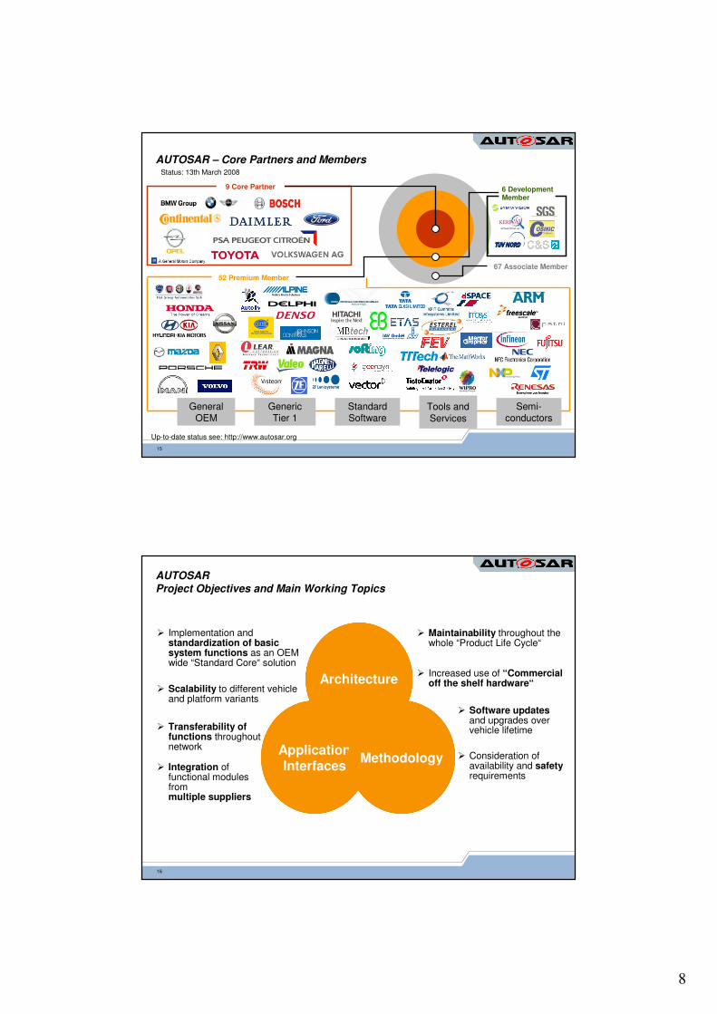
System Informationoverall system- bus systems, protocols,communication matrix andattributes (e.g. data rates, timing, …)
- function clustering - function deployment(distribution to ECU)
- ...
AUTOSAR-DescriptionEditor
System-
Description
System Description
� Network topology
- bus systems: CAN, LIN, FlexRay- connected ECUs, Gateways- power supply, system activation
� Communication (for each channel)
- K-matrix- gateway table
� Mapping / Clustering of SW components
AUTOSAR – Input Descriptions (3 of 3)Step 1c): Description of system
= tool based
38
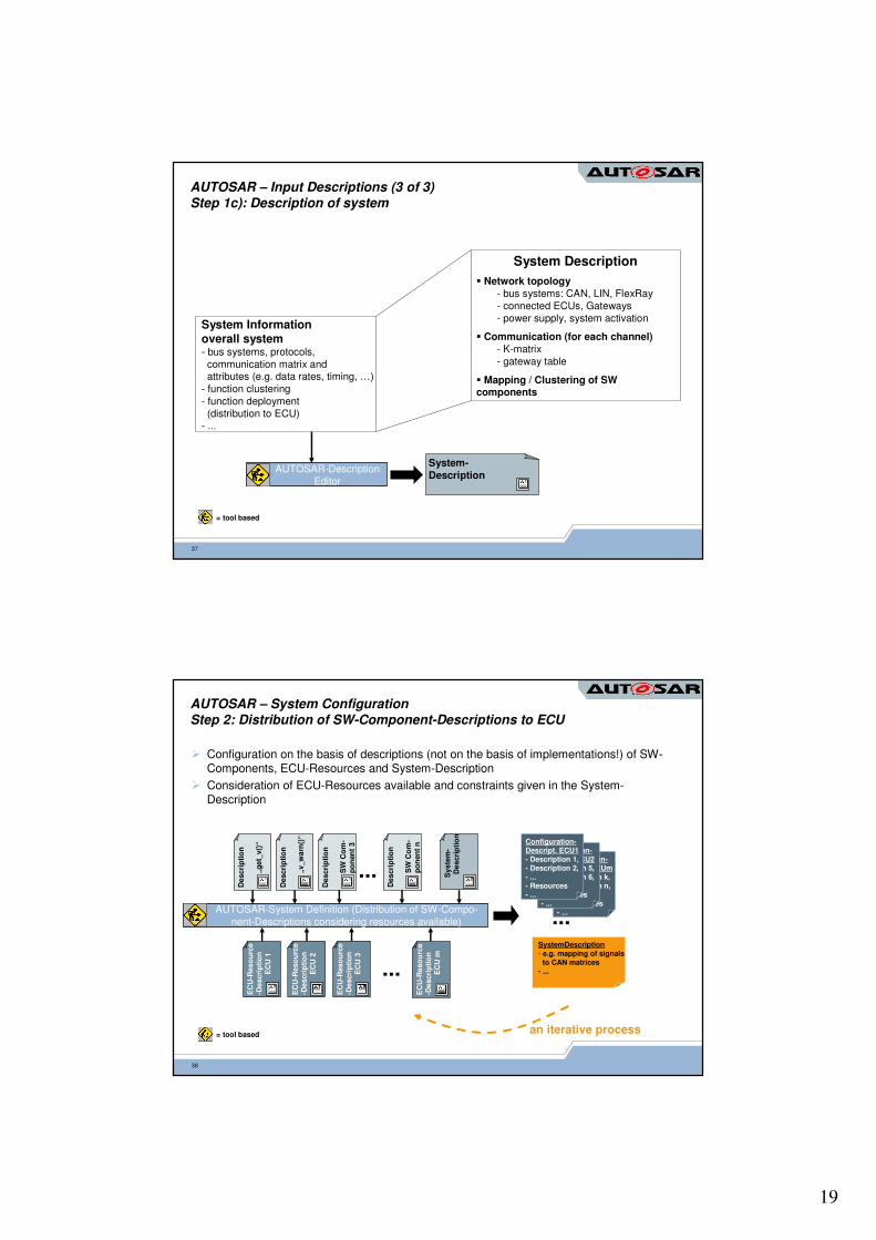
AUTOSAR – System ConfigurationStep 2: Distribution of SW-Component-Descriptions to ECU
� Configuration on the basis of descriptions (not on the basis of implementations!) of SW-Components, ECU-Resources and System-Description
� Consideration of ECU-Resources available and constraints given in the System-Description
Configuration-Descript. ECUm- Description k,- Description n,- ...- Ressources- ...
Configuration-Descript. ECU2- Description 5,- Description 6,- ...- Ressources- ...
AUTOSAR-System Definition (Distribution of SW-Compo-nent-Descriptions considering resources available)
...
...
Configuration-Descript. ECU1- Description 1,- Description 2,- ...- Resources- ...
...SystemDescription- e.g. mapping of signals
to CAN matrices- ...
EC
U-R
eso
urc
e-D
escri
pti
on
EC
U m
EC
U-R
eso
urc
e-D
escri
pti
on
EC
U 2
EC
U-R
eso
urc
e-D
escri
pti
on
EC
U 1
Syste
m-
Descri
pti
on
Descri
pti
on
„g
et_
v()
“
Descri
pti
on
„v_w
arn
()“
Descri
pti
on
SW
Co
m-
po
nen
t3
Descri
pti
on
SW
Co
m-
po
nen
tn
EC
U-R
eso
urc
e-D
escri
pti
on
EC
U 3
an iterative process= tool based

20
39
AUTOSAR - ECU Configuration Generator
AUTOSAR-RTE-Config-Info- communication mechanisms- transport protocols- ...
configurationof MCAL
configuration ofAUTOSAR OS
configuration ofthe AUTOSAR-RTE
Configuration of COM stack
etc
AUTOSAR-Configuration ECU1
AUTOSAR – ECU-ConfigurationStep 3: Generation of required configuration for AUTOSAR-Infrastructure per ECU
System Description- e.g. mapping of signals
to CAN matrices- ...
Configuration-Descript. ECU1- Description 1,- Description 2,- ...- Resources
= tool based
40
Application SWBody of theSW components
AUTOSAR-RTE
OS
Basic system functionscore functions, drivers
Hardware
MCAL
SW-Components ECU1(derived partially from the Virtual Function Bus)
OSGenerator
COMGenerator
Tooling
MCAL-Generator
AUTOSAR-RTE
Generator
AUTOSAR – Generation of Software ExecutablesStep 4: Based on the configuration information for each ECU (example ECU1)
AUTOSAR-Configuration ECU1
AUTOSAR-Library- communication- transport protocols, ...(code, macros, Objects, ...)
configurationof MCAL
configuration ofAUTOSAR OS
configuration ofthe AUTOSAR-RTE
Configuration of COM stack
COM

21
41
AUTOSAR Methodology – Conclusion
The E/E system architecture can be described by means of
AUTOSAR.1
A methodology to integrate AUTOSAR software modules has been designed.
3
AUTOSAR pushes the paradigm shift from an ECU based approach to a function based approach in automotive software development.
4
The meta model approach and the tool support for specifying the AUTOSAR information model allow working at the right level of abstraction.
2
42
Use case ‘Front-Light Management’ applying AUTOSAR
CAN Bus
ECU-Hardware
AUTOSAR RTE
Standardized Interface
Microcontroller Abstraction
ECUAbstraction
AUTOSARInterface
Std. Interface
StandardizedInterface
Communi-cation
Std. Interface
CAN Driver PWM
AUTOSAR Interface
Xenonlight
set_light(type, mode)
set_current (…)
ECU-Hardware
AUTOSAR RTE
AUTOSAR Int.
SwitchEvent
Standardized Interface
Microcontroller Abstraction
Std. AUTOSARInterface
Services
Std. Interface
ECUAbstraction
AUTOSARInterface
Std. Interface
StandardizedInterface
Communi-cation
Std. Interface
DIO
check_switch ()
AUTOSAR Interface
LightRequest
switch_event(event)
switch_event
(event)
request_light
(type, mode)
AUTOSAR Interface
Front-Light Manager
get_keyposition()
request_light(type, mode)
set_light(type, mode)
Microcontroller Abstraction
Standardized Interface
StandardizedInterface
Communi-cation
Std. Interface
CAN Driver
ECU-Hardware
AUTOSAR RTE
CAN Driver

22
--
Fol
ie 4
3
Topics for Research and Development
System configuration
Semi-automatic mapping of communication
--
Fol
ie 4
4
System Configuration.
Step 2 “System Configuration” has high complexity
Contains mappings ofData � Signals � Network CommunicationImplementations � SW-compositions � ECULogical HW resources � ECU
Under the existence of mappings constraints
System configuration is data structure covering the whole system description
SW ComponentDescription
SystemDescription
ECU ResourceDescription
1a 1c 1b
2Configure System
& generate extracts of ECU descriptions

23
--
Fol
ie 4
5
System Configuration.Communication Mapping.
Appli-
cation
SW-C
A
RTE
BSW
ECU I
Appli-
cation
SW-C
B
RTE
BSW
ECU II
Appli-
cation
SW-C
C
VFB
Sensor
Communication Bus
Communication Path
Hardware
AUTOSARInfrastructure
Ports
Application
Data Types
System Signals
Interaction Protocol
Data Units
Frames
--
Fol
ie 4
6
Communication Mapping.Level 1: Primitive Data Types ���� System Signals.
Communication between SW Components mapped onto Run Time Environment
Mapping defined as set of associations
Similar, but more complex mappings for
Complex data typesClient-server communication between SW-Components
Additionally, signal paths can be constraint

24
--
Fol
ie 4
7
Communication Mapping.Level 2: System Signals ����Run Time Environment ����Interaction Protocol Data Units.
Mapping of RTE signals to Communication Manager
Interaction layer defines also timing and triggering of ISignals
--
Fol
ie 4
8
Communication Mapping.Level 3: Interaction Protocol Data Units ���� Frames.
Mapping of Communication Manager to PDU Router
PDU Router deploys frames to different communication protocols
Frame definitions configure all communication stacks of full network
Different segments of system configuration will be used to configure each communication stack at each ECU
25
--
Fol
ie 4
9
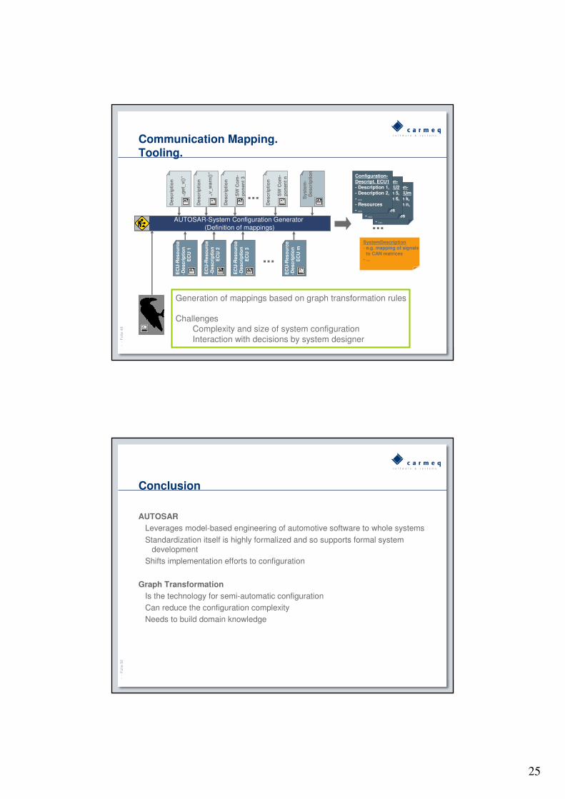
Communication Mapping.Tooling.
Configuration-Descript. ECUm- Description k,- Description n,- ...- Ressources- ...
Configuration-Descript. ECU2- Description 5,- Description 6,- ...- Ressources- ...
AUTOSAR-System Configuration Generator (Definition of mappings)
...
...
Configuration-Descript. ECU1- Description 1,- Description 2,- ...- Resources- ...
...SystemDescription- e.g. mapping of signals
to CAN matrices- ...
EC
U-R
eso
urc
e-D
escri
pti
on
EC
U m
EC
U-R
eso
urc
e-D
escri
pti
on
EC
U 2
EC
U-R
eso
urc
e-D
escri
pti
on
EC
U 1
Syste
m-
Descri
pti
on
Descri
pti
on
„g
et_
v()
“
Descri
pti
on
„v_w
arn
()“
Descri
pti
on
SW
Co
m-
po
nen
t3
Descri
pti
on
SW
Co
m-
po
nen
tn
EC
U-R
eso
urc
e-D
escri
pti
on
EC
U 3
Generation of mappings based on graph transformation rules
ChallengesComplexity and size of system configurationInteraction with decisions by system designer
--
Fol
ie 5
0
Conclusion
AUTOSAR
Leverages model-based engineering of automotive software to whole systems
Standardization itself is highly formalized and so supports formal system development
Shifts implementation efforts to configuration
Graph Transformation
Is the technology for semi-automatic configurationCan reduce the configuration complexityNeeds to build domain knowledge
26
--
Fol
ie 5
1
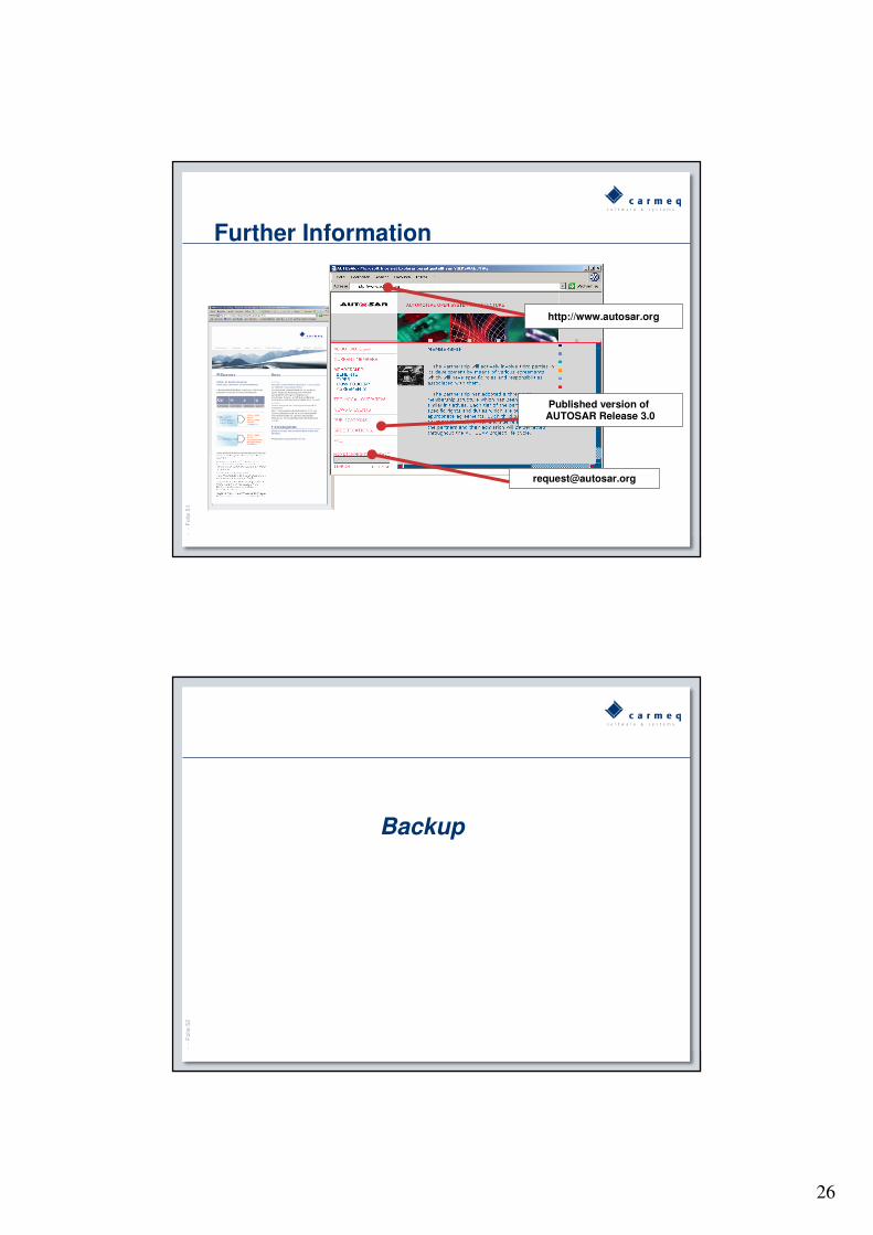
Further Information
http://www.autosar.org
Published version of AUTOSAR Release 3.0
--
Fol
ie 5
2
Backup

27
53
Challenges in Automotive E/E Development
� Extend product offering and increase product differentiation� Stable or decreasing development costs
� Strengthen brand image in the market� Propose specific features and functions across the product range
� Ensure long term competitiveness, as well as presence in emerging markets, through cost reduction
� Increase quality and reduce “non quality” costs
� Increasing share of electronics in vehicle value
� Electronics share (in value): 2004: 20% � 2015: 40%� (McKinsey, Automotive Electronics - Managing innovations on the road)
� Software share (in value): 2000: 4,5% � 2010: 13%� (Mercer Consulting, Automobile technologie 2010)
54
AUTOSAR Basic Software
ComplexDrivers
Microcontroller
AUTOSAR Runtime Environment (RTE)
Microcontroller Drivers Memory Drivers I/O Drivers
I/O Hardware Abstraction
Memory Hardware Abstraction
Memory ServicesSystem Services
Onboard DeviceAbstraction
CommunicationDrivers
CommunicationHardware Abstraction
CommunicationServices
Application Layer

28
55
Example: “NVRAM Manager” ensures the storage and maintenance of non-volatile data and is independent of the design of the ECU.
COM Drivers
Memory Hardware Abstraction
Mem Abstraction Interface
Ext. EEPROM Driver
µC
Memory Drivers
Int. EEPROM Driver
SPI Handler+ Driver
SPI EEPROM
EEPROM Abstraction
Memory Services
NVRAM Manager
External EEPROM
Spi_Read()
Spi_Write()
EepIf_Read()
EepIf_Write()
Complex
Drivers
Microcontroller
AUTOSAR Runtime Environment (RTE)
Microcontroller Drivers Memory Drivers I/O Drivers
I/O Hardware
Abstraction
Memory Hardware
Abstraction
Memory ServicesSystem Services
Onboard Device
Abstraction
Communication
Drivers
Communication
Hardware Abstraction
Communication
Services
Application Layer
Example
56
Glance on Application Interfaces – Body Domain
� CmdWashing is the interface defined by following information:� It is provided by the WiperWasherManager component through the
[Washer]Activation port� CmdWashing contains one data element command� Command is of type t_onoff� t_onoff is a RecordType, which describes a generic on/off information

29
57
AUTOSAR MetamodelFormal description of all methodology related information
� The metamodel is modeled in UML
� The structure of the information can be clearly visualized
� The consistency of the information is guaranteed
� Using XML, a data exchange format can be generated automatically out of the metamodel
METAMODEL
SW-Component
Datatype
Interface
MODEL
Mirror Adjustment
Mirror Actuator