Embed Size (px)
Citation preview
The 6th International Supercritical CO2 Power Cycles Symposium
March 27 - 29, 2018, Pittsburgh, Pennsylvania
A Gas Turbine-driven, Integrally Gear Compressor solution: Enabling the Carbon Capture
of the sCO2 Allam Cycle Power Plant.
Authors: David Freed, Principal, 8 Rivers Capital Brock Forrest, Senior R&D Engineer, 8 Rivers Capital Tushar Patel, Marketing Manager, Atlas Copco Gas and Process Jacob Duffney, Development Team Leader, Atlas Copco Gas and Process
Jacob Duffney is a Development Team Leader in the Atlas Copco Gas and Process Division, where he currently is focused on divisional Gearbox Development. His past experience within Atlas Copco has been diverse ranging from Compressor design, Order Handling lead, to Innovation Champion in Marketing. Prior to Atlas Copco Jacob worked at Sprung-Brett RDI on Electro-mechanical research projects for the USA DoD. He attended the University at Buffalo and earned a Bachelor and Masters of Science degree in Mechanical Engineering. Jacob is currently based in Cologne, Germany. For more information: [email protected] Tushar Patel is the Marketing Manager for Atlas Copco’s Gas and Process Division. With vast experience in global manufacturing, Bachelor’s degree in Mechanical Engineering and Master’s in Marketing Management, he oversees global product marketing and business development for centrifugal and direct-driven turbocompressors as well as expanders used in oil and gas and chemical/petrochemical processes, industrial gases and power generation. He is based in Houston, TX, USA. For more information: [email protected]
David Freed is a Principal at 8 Rivers Capital, where he is the company’s Project Manager for NET Power, LLC’s 50MWt demonstration plant. Mr. Freed also leads the Intellectual Capital Committee at 8 Rivers, focused on company-wide technology development and deployment. As part of the initial and current NET Power team, Mr. Freed has supported the technical and commercial sides of the business, helping raise over $140M in equity capital for the company and additional grant capital. Mr. Freed also helped oversee
the engineering, procurement, construction and now commissioning and testing of NET Power’s demonstration plant in La Porte, TX. Prior to joining 8 Rivers, Mr. Freed worked at Boston Consulting Group in New York. He attended Duke University where he earned a Bachelor of Science in Engineering with distinction and a Certificate in Markets and Management. Mr. Freed was recently named by Forbes as the feature for energy in its 30 Under 30 awards and as a guest judge for the 2018 awards. For more information: [email protected]

Brock Forrest is the Senior R&D Engineer at 8 Rivers Capital, LLC where he focuses on the design and development of the supercritical CO2 Allam Cycle. Mr. Forrest’s work has included the primary process modeling, engineering oversight, and procurement for NET Power’s 50MWt natural gas demonstration plant, the world’s first industrial scale supercritical CO2 power plant. Currently, Mr. Forrest is leading the design effort for the first 300MW commercial NET Power plant. Previously, Brock worked for MWH as a process engineer, where he was responsible for developing over 15 industrial plants functioning as aquatic life support systems. For more information: [email protected]
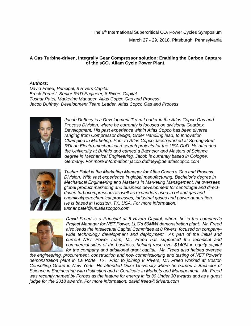
Introduction By using oxy-combustion and high-pressure supercritical CO2 (sCO2) in a recuperated cycle, the sCO2 Allam Cycle is able to generate power with near zero atmospheric emissions. This breakthrough technology has the potential to realize low cost and clean generation. One of the key design choices is the use of a combined turbine-compressor train. Implementing a supercritical CO2 compressor-turbine train has potential challenges. One of the initial design considerations is the type of compressor solution best suited to this application. This paper describes the process requirements for a supercritical CO2 compressor-turbine train, the technical challenges of implementation, and how an integrally geared (IG) compressor addresses these challenges. Process Description The Allam Cycle is an oxy-fired, trans-critical CO2 cycle with a low-pressure-ratio turbine. (Figure 1). The turbine exhaust gases are fed into a recuperator, cooled, water is condensed and separated, and the remaining vapor phase CO2 is compressed and pumped up to high pressure before recovering the heat in the recuperator. The hot, high-pressure CO2 then is added as coolant to the combustor inlet to achieve a final turbine inlet temperature of approximately 1150℃.
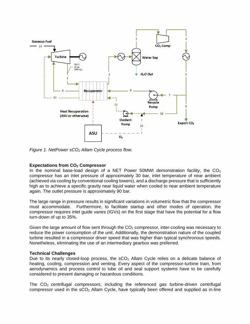
Figure 1. NetPower sCO2 Allam Cycle process flow. Expectations from CO2 Compressor In the nominal base-load design of a NET Power 50MWt demonstration facility, the CO2 compressor has an inlet pressure of approximately 30 bar, inlet temperature of near ambient (achieved via cooling by conventional cooling towers), and a discharge pressure that is sufficiently high as to achieve a specific gravity near liquid water when cooled to near ambient temperature again. The outlet pressure is approximately 90 bar. The large range in pressure results in significant variations in volumetric flow that the compressor must accommodate. Furthermore, to facilitate startup and other modes of operation, the compressor requires inlet guide vanes (IGVs) on the first stage that have the potential for a flow turn-down of up to 35%. Given the large amount of flow sent through the CO2 compressor, inter-cooling was necessary to reduce the power consumption of the unit. Additionally, the demonstration nature of the coupled turbine resulted in a compressor driver speed that was higher than typical synchronous speeds. Nonetheless, eliminating the use of an intermediary gearbox was preferred. Technical Challenges Due to its nearly closed-loop process, the sCO2 Allam Cycle relies on a delicate balance of heating, cooling, compression and venting. Every aspect of the compressor-turbine train, from aerodynamics and process control to lube oil and seal support systems have to be carefully considered to prevent damaging or hazardous conditions. The CO2 centrifugal compressors, including the referenced gas turbine-driven centrifugal compressor used in the sCO2 Allam Cycle, have typically been offered and supplied as in-line

(between bearing) API 617 Ch.2 technology. Although this technology has had a long and proven history, it also presents limitations and drawbacks when it comes to CAPEX, maintenance and flexibility. An integrally geared compressor arrangement addresses for these limitations; however, a typical gearing arrangement limits the size and number of stages that can be mounted on the machine. In most cases, an external intermediate gearbox is used to vary the IG compressor input speed, but the industry typically rejects this solution due to the perceived complexity of two separate gearboxes. Technology Solutions With in-line compressor technology, the aerodynamic components are mounted on the same shaft, requiring them to be sized based on a given driver speed. Integrally geared (IG) compressors, have stage design speeds that can be selected completely independent of the optimum driver speed. This makes it possible for the aerodynamic components to be tailored to the thermodynamic requirements without being bound by a speed requirement—which is the case for the directly coupled in-line compressors—thus allowing for higher loading per compression stage. Because each impeller itself is a stage with its own casing and inlet and discharge connections, IG compressors accommodate intercooling between stages to reduce adiabatic losses. This allows for greater flexibility and more efficient compression. Due to nature of its concept and design, each impeller of an integrally geared compressor is mounted on pinion that allows it to run at its optimal speed, ensuring the matching of the wheel geometry with speed. That is the essential part of best efficiency for dynamic compression technology as compared to positive displacement. This arrangement thus not only results in better flexibility in order to: (1) Incorporate side streams coming in or going out. (2) Provide intercooling after each stage (close to theoretical / isothermal compression). (3) Allow to handle multiple gases on same compressor instead of having separate compression packages. (Figure 2). (4) Arrange an expander (turbine) and a compressor on same gearbox, combining two machines into CompanderTM. (Figure 3 and 4). In addition, this arrangement contributes to better overall efficiency, due to the highest stage efficiency, which is achieved by selecting the right impeller type (Open, Shrouded, 2D, 2.5D or 3D) and speed combination, as well as due to total isothermal efficiency. See Figure 5.
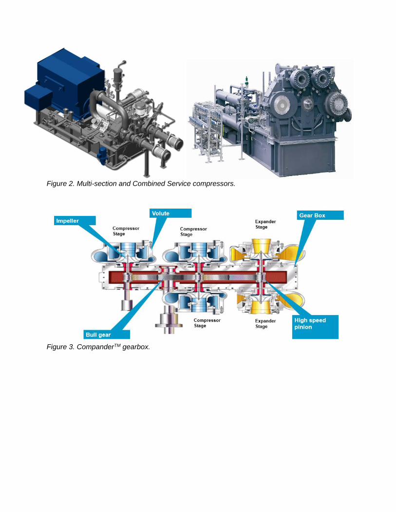
Figure 2. Multi-section and Combined Service compressors.
Figure 3. CompanderTM gearbox.

Figure 4. CompanderTM package.
Figure 5. Open and shrouded impeller. IG compressors are considered high head compressor due to their speed, which is relatively higher than any other compression technology. As a result, less impellers are needed to reach the same compression ratio / head requirement; also, less material is required than for the single casing used by in-line compressors. This creates a more compact footprint, requiring less real estate on shop and plant floors, helping to lower CAPEX.
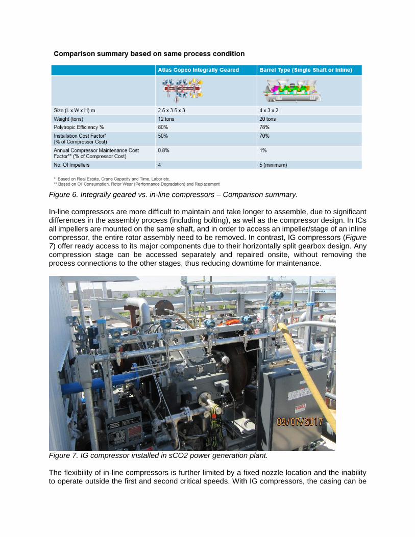
Figure 6. Integrally geared vs. in-line compressors – Comparison summary. In-line compressors are more difficult to maintain and take longer to assemble, due to significant differences in the assembly process (including bolting), as well as the compressor design. In ICs all impellers are mounted on the same shaft, and in order to access an impeller/stage of an inline compressor, the entire rotor assembly need to be removed. In contrast, IG compressors (Figure 7) offer ready access to its major components due to their horizontally split gearbox design. Any compression stage can be accessed separately and repaired onsite, without removing the process connections to the other stages, thus reducing downtime for maintenance.
Figure 7. IG compressor installed in sCO2 power generation plant. The flexibility of in-line compressors is further limited by a fixed nozzle location and the inability to operate outside the first and second critical speeds. With IG compressors, the casing can be
rotated to orient the nozzles in any direction, and each impeller runs at its own speed to accommodate variations in the process conditions. It’s true that an integrally geared (IG) compressor arrangement provides solutions for many of the challenges of in-line technology, but its typical gearing arrangement limits the size and number of stages that can be mounted on the machine. As all geared machines experience high speed mesh interactions, there are gear diameter limitations due to gearing pitch line velocity (PLV) constraints. The formula below shows the relationship between rotational speed, diameter and PLV:
𝑉: Pitch line velocity (m/s)
𝑑: Gear pitch line diameter (m) 𝑉(𝑚/𝑠) = (𝜋∗𝑑∗𝑛
60)
𝑛: Revolutions per minute Coping with the higher input speed from a gas or steam turbine means that the spacing is reduced in a typical gearing arrangement. In most cases, when an IG compressor is employed in a gas- or steam-driven train, it is designed and offered with the use of an external intermediate gearbox to vary the input speed, or it is driven through a pinion. Many times, an external intermediate gearbox is used to vary the IG compressor input speed, but the industry typically rejects this solution due to the perceived complexity of two separate gearboxes. Still, the IG compressor’s unique, compact configuration allows it to be directly coupled with the gearbox, and its ability to vary impeller geometry and design speeds during design phase helps avoid train torsional issues. Other Challenges and Solutions Along with the main technological challenges of allocating the necessary combination of machine components in a Compressor-Turbine-Generator train there are many additional considerations that influence the design and layout. The additional considerations range from rotordynamics to design of the process sealing system. Aerodynamic Considerations As gas enters the path of an impeller, certain aerodynamics can cause cooling in localized areas. If the gas cools enough, it can change phases, producing pockets of fluid. Due to the high density of CO2, it is necessary to try and avoid phase changes in all operational cases. A worst-case scenario would be if an upstream pocket of CO2 liquid was accidentally injected into the suction of the compressor. This can be avoided through proper thermodynamic analysis throughout the compressor cycle. The aerodynamics must be designed to address any nature of compressor trips, hot and cold day cases, variable pressures and proper drainage to ensure no liquid CO2 remains in the system. Gas dynamic modeling can help determine the need for any changes in geometry, impeller dynamics or blade profile to prevent condensation due to aerodynamics. Rotordynamic Considerations In most cases, a compressor-turbine-generator train has three or more pieces of equipment connected in a complex rotordynamic system. This usually consists of a gearbox, compressor, turbine, generator and the associated couplings. Accounting for the interaction of these
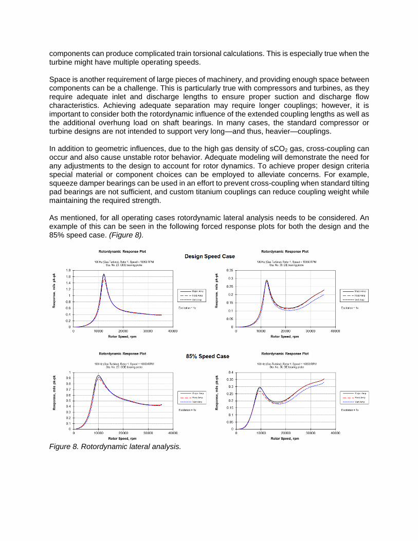
components can produce complicated train torsional calculations. This is especially true when the turbine might have multiple operating speeds. Space is another requirement of large pieces of machinery, and providing enough space between components can be a challenge. This is particularly true with compressors and turbines, as they require adequate inlet and discharge lengths to ensure proper suction and discharge flow characteristics. Achieving adequate separation may require longer couplings; however, it is important to consider both the rotordynamic influence of the extended coupling lengths as well as the additional overhung load on shaft bearings. In many cases, the standard compressor or turbine designs are not intended to support very long—and thus, heavier—couplings. In addition to geometric influences, due to the high gas density of sCO2 gas, cross-coupling can occur and also cause unstable rotor behavior. Adequate modeling will demonstrate the need for any adjustments to the design to account for rotor dynamics. To achieve proper design criteria special material or component choices can be employed to alleviate concerns. For example, squeeze damper bearings can be used in an effort to prevent cross-coupling when standard tilting pad bearings are not sufficient, and custom titanium couplings can reduce coupling weight while maintaining the required strength. As mentioned, for all operating cases rotordynamic lateral analysis needs to be considered. An example of this can be seen in the following forced response plots for both the design and the 85% speed case. (Figure 8).
Figure 8. Rotordynamic lateral analysis.

Lube Oil Considerations When aligning the components in a turbine-compressor train, the type of oil, set points, capacity and backup solutions must all be accounted for. If the function of a slow-roll is necessary, it is essential to ensure proper lubrication of all components when this occurs, as well. If a unified oil system is necessary, all components in the train must be on the same grade of oil, the most common being VG32 and VG46. Otherwise, the differences in oil characteristics could cause issues with the rotor dynamic designs in the field. The capacity of the oil system required for an entire train can be very difficult to size properly. Each of the components’ oil requirements in various operating cases must be included, as well as capacity parameters such as retention time and rundown volume. To maintain proper lubrication in all operating conditions, the component set points and turbine slow-roll functionality must both be considered. Once all start, stop and operating range pressures and temperatures are aligned, it may mean that the system sets alarm or trip conditions due to the lowest common denominator. In slow-roll situations, where the turbine rotates to prevent bowing of the main shaft (typically required only during the cooling phase), all components must be fully lubricated through continuous oil circulation. Certain arrangements could also employ jacking bearings for highly loaded bearings. In the latter case, a secondary high-pressure oil pump uses hydrostatic force to ensure separation of the shaft and bearing pads. A typical oil system includes an auxiliary oil pump in case the main pump fails ensure protection of the lubricated components. In addition, some arrangements such as those employing a slow-roll case require an emergency lubrication source to aid in a power outage situation. This prerequisite can be implemented in several ways. One way is by using a DC- or AC-driven pump that is connected to an uninterrupted power supply (UPS), such as a battery bank or a generator. Another way is to use a rundown tank that is elevated to provide ample pressure. Though the tank is a simpler solution, it does require additional oil reservoir capacity. Seal Support Considerations Dry gas seals (DGS) are essential to the functionality of a combined turbine-compressor train, but their tight operating tolerances can make a phase switch particularly dangerous. The risk here is that, because sCO2 is extremely sensitive to pressure and temperature changes, there is always the possibility of a phase change. It should be noted this issue will be present in not only IG compressors but rather with any rotating machinery employing a DGS. As the gas crosses the seal, it moves from high to low pressure and experiences a corresponding temperature drop. If the initial temperature of the sCO2 is not sufficient, this can cause the gas to move “below the dome” and into a partial liquid phase. Such a situation could cause catastrophic damage to the DGS, as the gas must remain stable to ensure separation of the rotational and stationary seal faces. Adequate modeling is required to ensure the temperature of the sCO2 is high enough when crossing the seal to prevent liquid CO2 formation. Heat tracing or the use of a seal gas heater can also be employed as a backup solution, both for the feed side of the DGS and in the ventilation lines so they remain clear from blockage. A general minimum seal gas temperature used is 42°C in order to ensure proper separation from the critical point for the process in this example. To ensure proper selection of this temperature one should use a pressure-enthalpy diagram.

During slow-roll, not only does the lubrication of the bearings and gearing need to be considered, but also the interaction of the seals. Due to the design of a DGS, there are conditions where the seal does not produce “lift-off,” thereby causing wear that can lead to failure. Although this nonfunctional range is very limited, it typically falls within a slow-roll speed and therefore must be eliminated. This critical operating case must be discussed with the seal provider and turbine supplier. Due to the design of DGS and the density of CO2, venting safely is another challenge. Typically when this is required, the gas is on a lower mole weight than air (28.966 kg/kmol), so it floats up into the atmosphere. One example would be when a fuel gas booster is compressing natural gas (19.00 kg/kmol) and a vent stack or flare is used to dispose of vented process gas. As long as the stack is tall enough, it does not present a hazard. The issue with CO2 is that, due to its molecular weight (44.01 g/mol) it will naturally sink. This means that wherever the process is vented, the CO2 could collect and displace the air. Though this would not create an explosive situation, it would be dangerous to any living aerobic organisms. For this reason, it is imperative to avoid venting into a contained or inhabited area. Controls Considerations All machines have individual start permissives, depending on the process, support system and startup cycle times. In a complex compressor-turbine-generator train, this must be carefully coordinated — especially when the compressor and turbine are linked both mechanically and through the process cycle, as they are in an sCO2 Allam Cycle. Like the oil system, the start permissives should always abide by the lowest common denominator in order to avoid component damage. With turbines, there is a defined startup time to allow for proper heating of the components and system. If enough time is not allotted, then forces created by uneven thermal growth can damage the complex turbine internals. Depending on the turbine’s design, materials and operating conditions, this cycle can range from minutes to hours before reaching full speed and load. It may also be desirable during startup and shutdown procedures to vary the compressor load on the turbine shaft. This can be accomplished through a number of combinations involving the ramping of the compressor suction pressure, ramping the discharge pressure and/or ramping the flow rate through the use of recirculation valves and integral guide vanes. This can have a significant rotordynamic impact on compressors, because most integral compressor rotor shafts operate between the first and second natural frequencies. When normally driven such as by a motor, the transition through the first natural frequency is relatively quick. Through this arrangement the resulting excitation of the compressor shafts is only momentary, if at all. However, in a slow acceleration arrangement such as turbine startup, the time spent in the first critical speed can become very hazardous. Coordination between the turbine vendor and the compressor vendor can help to properly define these critical ranges and plan how to move through them quickly without significantly increasing the turbine heat load. An example estimate of which speeds to avoid for the IG Compressor is shown in the following chart. This chart was provided at the time of order to help with plant startup estimations. It also displays two corresponding acceleration ramp rates to give some perspective to the chart. (Figure 9).

Figure 9. Estimated critical speeds of the integrally geared compressor. Variable speed cases can similarly excite the components in a compressor-turbine-generator train. Though most trains are designed to operate at a fixed speed due to the added complexity of speed control, it is important to define variable speed cases early in the project. This allows the various components in the train to work together and even compensate for other components’ weaknesses. An example of this is using IGVs to accommodate stage mismatching during the slow acceleration of the startup sequence. It is important to know why and when a component might request a trip. The customer may decide that there are situations where, even if a component calls for a trip, the train continues to operate. This would be a sacrificial measure used to protect the most vital pieces of the train. For example, if an intermediate gearbox calls for a trip due to high bearing temperature, this could be ignored to protect the turbine by allowing the entire train to shut down through a planned cooling process. Though this may cause damage to the gearbox bearings, it would help prevent warping of the turbine shaft. Emergency situations are another consideration when designing industrial machinery with several pieces of equipment are coupled together in the same train. If one component experiences an issue, it cannot stop independently of the others. It must slow down with the whole train. For example, if there was a leak in an independent oil system that caused a fire, the oil system could be immediately shut down. If the oil system were part of a large train, however, the high rotational inertia would cause the train to continue to rotate and pump oil into the fire for a while.
Scenarios such as this one need to be discussed early on, and the protocol for handling them needs to be clearly defined in order to limit danger and damage. Conclusion Creating a combined turbine-compressor-generator train is a complex undertaking with many considerations, but there are benefits to consolidating equipment. The additional efficiency, reduced footprint and reduction of components help to simultaneously reduce CAPEX costs while improving performance. IG compressor technology adds to the advantages of a more integral train design, thereby helping to make the sCO2 Allam Cycle technology more commercially attractive.
References:
API – American Petroleum Institute: API Recommended Practice 684, API Standard
Paragraphs, Rotordynamic Tutorial: Lateral Critical Speeds, Unbalance Response, Stability,
Train Torsionals, and Rotor Balancing, second edition, August 2005.
Boyce, M. (2003). Centrifugal compressors: A basic guide. Tulsa, Oklahoma: PennWell
Corporation.
Chellini, R. (2015). New High-Pressure CO2 Compressor. An Integrated solution for reliable operation. CompressorTech2 Magazine, July 2015. Struck, H., Patel, T. (2017). Ensuring integrally-geared compressor reliability with API 617. 10 Forum de Turbomaquinas, November 2017. Wiebe, F. (2016). The two sides of the same coin. World Fertilizer Magazine, November 2016.