Embed Size (px)
Citation preview

Tharsis-radial graben systems as the surface manifestation of
plume-related dike intrusion complexes: Models and implications
Lionel WilsonEnvironmental Sciences Department, Lancaster University, Lancaster, UK
Department of Geological Sciences, Brown University, Providence, Rhode Island, USA
James W. Head IIIDepartment of Geological Sciences, Brown University, Providence, Rhode Island, USA
Received 5 September 2001; revised 15 February 2002; accepted 28 March 2002; published 1 August 2002.
[1] Several zones of graben (Memnonia, Sirenum, Icaria, Thaumasia, and Claritas Fossae)extend radially away from the Tharsis rise in the southern hemisphere of Mars for distancesof up to 3000–4000 km. These graben systems are commonly interpreted to be related toregional tectonic deformation of the Tharsis rise associated with either upwelling orloading. We explore the possibility that these giant Tharsis-radial graben systems could bethe surface manifestation of mantle plume-related dike intrusion complexes. Emplacementof dikes causes near-surface stresses that can produce linear graben, and lateral dikeemplacement related to plumes on Earth can produce dike swarms with lengths of manyhundreds to several thousands of kilometers. We develop a Mars dike emplacement modeland explore its implications. We find that the properties (outcrop patterns, widths, anddepths) of the extensive Tharsis-radial graben systems are consistent with an origin throughnear-surface deformation associated with lateral propagation of magma-filled cracks(dikes) from plumes beneath Tharsis, particularly beneath Arsia Mons and Syria Planum.Such dikes are predicted to extend through the crust and into the upper mantle and can havewidths of up to several hundred meters. Analyses of summit caldera complexes on Martianvolcanoes imply that the magma supply from the mantle into shallower reservoirs isepisodic on Mars, and we interpret the graben systems to be large swarms of laterallyemplaced giant dikes resulting from the tapping of melt from episodically rising mantleplumes in a buffered magma supply situation. The magmatic interpretation of the Tharsis-radial graben potentially removes one of the conundrums of Tharsis tectonics in which itappeared necessary to require two distinct modes of support for Tharsis in order to explainthe presence of radial graben on both the elevated flanks (attributed to isostatic stresses) andoutside the rise (more consistent with flexure): dikes capable of forming the observedgraben can be emplaced under a wide range of stress fields, including zero stress. The factthat almost no eruptive features are associated with the graben further restricts the ranges ofmagma density to values between �3100 and 3200 kg m�3 and crustal stress to tensionsless than �30 MPa. Eruptions from giant dikes would be more likely to occur in regionswhere the crust was thinner, such as the northern lowlands, providing a potentialmechanism for emplacement of recently documented Early Hesperian volcanic plains (Hr)there. Dike-related graben systems represent efficient mechanisms of lateral heat transfer inthe crust and near-surface environments. Lateral dike intrusions could penetrate thecryosphere and cause melting and release of groundwater, as in the Mangala Valles area,and could also drive hydrothermal circulation systems. The geometries of such dikesystems will create barriers which are likely to influence regional to global groundwaterflow patterns, which may help to explain the abundance of outflow channel sources ineastern Tharsis. Improved knowledge of the Martian crust and mantle density structure willhelp to refine this analysis and to provide estimates of the magma densities for dikesunderlying specific graben. INDEX TERMS: 6225 Planetology: Solar System Objects: Mars; 5480
Planetology: Solid Surface Planets: Volcanism (8450); 5475 Planetology: Solid Surface Planets: Tectonics
(8149); 5470 Planetology: Solid Surface Planets: Surface materials and properties; 5430 Planetology: Solid
Surface Planets: Interiors (8147); KEYWORDS: Mars, volcanism, dikes, graben, Tharsis
JOURNAL OF GEOPHYSICAL RESEARCH, VOL. 107, NO. E8, 10.1029/2001JE001593, 2002
Copyright 2002 by the American Geophysical Union.0148-0227/02/2001JE001593$09.00
1 - 1

1. Introduction
[2] A number of zones of graben and tension cracksextend generally radially away from the Tharsis rise in thesouthern hemisphere of Mars [Wise et al., 1979a, 1979b;Plescia and Saunders, 1982], including Memnonia Fossae,Sirenum Fossae, Icaria Fossae, Thaumasia Fossae, andClaritas Fossae (Figures 1 and 2). These graben and tensioncrack systems consist of from three to more than a dozenlinear structures that occur parallel to one another, arediscontinuous to continuous, sometimes en echelon, andextend in straight to broadly arcuate patterns for up to3000–4000 km from central Tharsis (Table 1). In thehighlands distal to Tharsis, they cut across a wide rangeof highland units of Noachian and Hesperian age, andtoward Tharsis they are embayed and covered by variousunits of Hesperian and Amazonian age, but in some placessome of them cut these latter units [Scott and Tanaka, 1986;Tanaka et al., 1992]. These data strongly suggest that thesegraben and tension crack systems formed throughout theperiod of evolution of Tharsis and the emplacement of itsextensive volcanic cover [Tanaka et al., 1992; Banerdt etal., 1992].[3] Graben and fractures arrayed radially around a central
feature have been attributed to (1) faulting due to regionalstrain associated with isostatic, dynamic, or thermal uplift[e.g., Wise et al., 1979b; Frey, 1979; Banerdt et al., 1982;Sleep and Phillips, 1985; Tanaka and Davis, 1988; Cyr andMelosh, 1993], (2) radial dike emplacement and associatednear-surface faulting [e.g., Head and Wilson, 1992; Parfittand Head, 1993; Grosfils and Head, 1994a, 1994b, 1995],and (3) a combination of these factors [e.g., Grosfils andHead, 1994a; Ernst et al., 1995; Mege and Masson, 1996a,1996b].[4] In the Tharsis region of Mars the most common
interpretation of the extensive radial graben and fracturesystems is that they are related to lithospheric deformationassociated with the formation of Tharsis itself. Comparisonof the major radial graben systems to stress models [e.g.,Banerdt et al., 1992] has shown that more than one litho-spheric deformation mechanism is required to explain theenormous extent of the concentric extensional stressesrequired by the observed radial graben system. For exam-ple, concentric extensional stresses on top of the Tharsisrise are produced only by isostatic models, but theseproduce compressional stress off the rise in the area ofthe observed graben swarms owing to the large radius ofuplift with respect to the planetary radius. In contrast, onlyflexural loading predicts concentric extensional stresses offthe rise. Thus isostatic stresses are required to produce theobserved radial graben on top of the rise, and flexuralloading stresses are required to produce the graben on theflanks and distal portions of the rise. Several workers haveattempted to reconcile these predictions with the temporalsequence of formation of radial graben [e.g., Watters andMaxwell, 1983] in the history of Tharsis [e.g., Golombekand Phillips, 1983; Sleep and Phillips, 1985; Banerdt andGolombek, 1989]. Detailed mapping of the structures andtheir temporal relationships, and comparison to the historyof Tharsis, has revealed, however, the conundrum thatmany sets of radial fractures that extend the entire distancefrom the central regions of Tharsis to its periphery appear to
have formed simultaneously, or at least closely interspersedin time.[5] As pointed out by Banerdt et al. [1992, p. 292], ‘‘it is
not clear how to form such extensive radial fractures in asingle event, when the stress models seem to require twodistinct events. Resolution of this apparent paradox isrequired before self-consistent scenarios can be constructedthat attempt to link the stress systems with the evolution ofthe lithosphere and asthenosphere in the Tharsis region.’’More recent analyses using Mars Global Surveyor datasuggest that it may be possible to explain most of the faults(both on and off the rise) in a unified fashion by flexurealone, with the faulting within Tharsis being caused byregional deformation not resolved by earlier data sets[Banerdt and Golombek, 2000].[6] We suggest that another potential solution is the
lateral emplacement of magma-filled cracks, that is, dikes,in which the magma pressure, rather than the regional stressfield, is the dominant factor causing near-surface stressesthat produce linear fractures and graben [e.g., Head andWilson, 1993; Wilson and Head, 2000]. We assume that thedikes are fed by magma rising from the head of a mantleplume. The stresses caused by plume-related uplift (i.e.,least principle stress horizontal and oriented circumferen-tially to the plume center) define the initial orientations ofthe intrusions, forming dikes rather than sills. Thereafter themagma pressure in the dikes dominates the regional stressfields and ensures that the intrusions continue to propagatelaterally as dikes. Lateral dike emplacement related toextensive mantle plumes can produce dike swarms whoselateral dimensions are measured in hundreds to thousands ofkilometers (see reviews by Ernst et al. [1995, 2001]). Forexample, the Mackenzie dike swarm, the largest known onEarth, consists of a radiating 100� fan of dikes that extendmore than 2500 km from the source region [e.g., Fahrig andWest, 1986]. These dikes were emplaced in the CanadianShield about 1.27 Gyr ago in association with a mantleplume; magnetic fabric data show that vertical magma flowin the dikes characterized the central upwelling region andlateral flow dominated at all distances beyond it [Ernst andBarager, 1992].[7] On the basis of the commonly observed correlation of
radial dike emplacement and surface faulting [e.g., Pollardet al., 1983; Pollard, 1987; Rubin, 1992], we explore thepossibility that the giant Tharsis-radial graben systemscould be the surface manifestation of plume-related dikeintrusion complexes [Mege and Masson, 1996a]. We firstdocument the basic characteristics of the graben and fracturesystems, then develop a model of giant dike emplacementunder Mars conditions, and finally explore the implicationsof our results.
2. Tharsis Graben and Fracture Zones
[8] Among the several types of extensional structuresobserved on Mars [e.g., Davis, 1990; Banerdt et al., 1992],two types, simple graben and tension cracks, dominate thesouthern radial circum-Tharsis systems. Simple graben arelinear, straight-walled depressions with a flat floor and arecharacterized by inward dipping normal faults which havetypically undergone displacements of tens to hundreds of
1 - 2 WILSON AND HEAD: THARSIS-RADIAL GRABEN AS DIKE INTRUSIONS

meters. The simple geometry, consistent over hundreds ofkilometers, suggests that the two faults are of equal impor-tance, perhaps initiating at a common point and thenpropagating to the surface [Rubin, 1992]. These simplegraben are long (tens to many hundreds of kilometers),relatively narrow (a few kilometers wide), and characterizedby spacings of a few tens of kilometers (and locally muchless, as in Claritas Fossae and Ceraunius Fossae). Tensioncracks, narrow, deep, v-shaped structures, are morphologi-cally distinct from simple graben in that they lack a flatfloor [Tanaka and Golombek, 1989].[9] As pointed out above, several zones of graben and
tension cracks extend generally radially away from theTharsis rise in the southern hemisphere of Mars [Wise etal., 1979a, 1979b; Plescia and Saunders, 1982] (Figures 1and 2). In order to provide a general characterization of the
systems or zones, we have divided them into several groupsand subgroups (Figure 2 and Table 1) and have used Vikingand MGS image and altimetry data to document their type,system length, segment length, spacing, width, depth, cross-sectional profile and structure (Figures 3–10), and associ-ations.[10] Memnonia Fossae (Figures 1–4) consist of 4–6
parallel and tangential graben, fractures, and pitted linearstructures typically separated by about 20 km and alignedradially to Arsia Mons, extending from 1100 to 2700 kmfrom the summit of Arsia Mons. Widths are typically 1–2km, and depths are 100–200 m but can be up to 450 m. Mostof the structures in this system cut Noachian and EarlyHesperian-aged units distal to Tharsis, but one or two cutHesperian-Amazonian (AHt3) and Early Amazonian (AHt4)units flanking Arsia Mons [Scott and Tanaka, 1986] (Figure
Figure 1. Mars Global Surveyor (MGS) Mars Orbiter Laser Altimeter (MOLA) [Smith et al., 2001]color-coded topographic map superposed on a MOLA topographic gradient map showing topographicdetails. Central Tharsis topography above 4000 m is shown in red. Compare with Figure 2, which is asketch map of the same area and shows the distribution of structures radial to Tharsis and geologicalunits. Note the major transition in surface topography at the margins of the Tharsis rise (below about2000 m), where radial flows from Tharsis volcanoes give way to ancient deformed and more heavilycratered terrain. Mercator projection.
WILSON AND HEAD: THARSIS-RADIAL GRABEN AS DIKE INTRUSIONS 1 - 3

2). Sirenum Fossae (Figures 1, 2, 5, and 6) consist of 1–6parallel graben, fractures, and linear pit chains with a typicalspacing of about 12–14 km and arrayed radially to ArsiaMons, extending from 1100 km to at least 3700 km from theArsia Mons summit. They have typical widths of about 1–2km and depths of 100–300 m, but ranging up to 500 m.Structures of Sirenum Fossae cut Noachian and Early Hes-perian-aged units distal to Tharsis, and none intersect theyounger flanking Arsia flows of Daedalia Planum. Anunnamed set of graben and fissures is located higher on theflanks of Arsia (Figures 2 and 7), extends about 1600 kmfrom the summit of Arsia, and cuts units ranging from Ht1 toAt5. These structures range in depth from 50 to 70 m, withone up to several hundred meters deep. A few short segmentsthat parallel this trend are seen distally to the occurrence in
Figure 5 about 2000–2800 km away from the summit ofArsia Mons in the Noachain-Hesperian terrain (see Figure 2).Icaria Fossae form an extensive system of fractures andgraben that are oriented radially and subradially to SyriaPlanum (Figures 1, 2, and 8), extending from about 800 to4000 km from the summit of Syria Planum. This is a veryextensive system that predominantly cuts Noachian andEarly Hesperian-aged units. The detailed segment shown inFigure 6 illustrates the relatively high density of thesefeatures locally and shows that their depths are �50–200m. Claritas Fossae (Figures 1, 2, and 9) form a dense andextensive system of graben and fractures that are generallyradial to Syria Planum, extending in a SSE direction fromabout 1000 to 2800 km from the summit of Syria Planum.Structures there are closely spaced and are generally 25–100
Figure 2. Distribution of graben and fracture systems in southern Tharsis. Dark lines radial to Tharsisshow locations of graben and fracture systems mapped at 1:15 million scale [after Scott and Tanaka,1986; Greeley and Guest, 1987]. Stars indicate location of summits of Arsia Mons (left) and SyriaPlanum (right) edifices, to which most of the structures are radial. Compare this figure to Figure 1 andnote that the radial graben and fracture systems extend well beyond the presently preserved hightopography of Tharsis. Boxes show the location of Viking Orbiter enlargements and MOLA altimetryprofiles shown in Figures 3–10. Letters represent geologic unit designations; Am is Amazonian MedusaeFossae Formation, and others represent Tharsis-related volcanic units of Hesperian and Amazonian agediscussed in the text. A significant part of the area is composed of more heavily cratered units distal toTharsis and not labeled (compare to Figure 1). Units and boundaries are from Scott and Tanaka [1986]and Greeley and Guest [1987]. Mercator projection.
1 - 4 WILSON AND HEAD: THARSIS-RADIAL GRABEN AS DIKE INTRUSIONS

m deep. Thaumasia Fossae (Figures 1, 2, and 10) consist of aclosely spaced set of graben located primarily south of theThaumasia Rise. Structures there are about 25–150 m deep.[11] In summary, these graben and tension crack systems
consist of from three to more than a dozen linear structures(Figures 2–10) that occur parallel to one another, arediscontinuous to continuous, sometimes en echelon, andextend in straight to broadly arcuate patterns for up to3000–4000 km from central Tharsis (centered primarily atArsia Mons and Syria Planum) (Figures 1 and 2; Table 1).These data provide a basis on which to assess the plausi-bility of dike emplacement as a mechanism for formation ofthe graben and fracture systems in southern Tharsis.
3. Giant Dike Model Development
[12] Current understanding of the emplacement of dikesfrom a rising mantle plume head implies that the followingstages occur (Figure 11). The partial melt from a finitevertical extent of the plume head is segregated by compac-tion into a region of much smaller vertical extent [Maaloeand Scheie, 1982; McKenzie, 1985; Scott and Stevenson,1986]. This region of concentrated melt is positively buoy-ant in the host rocks from which it was derived and so canpropagate upward as a diapiric body. As it rises it encoun-ters cooler surrounding rocks, and the rheological responseof these rocks to its passage becomes progressively lessviscoplastic and more viscoelastic. Rubin [1993a] showshow the aspect ratio of the magma body then changes fromits original relatively equant shape, becoming progressivelymore elongate in the plane at right angles to the direction ofleast principle stress in the host rocks, here horizontal andoriented circumferential to the center of the plume, so that itassumes a more nearly dike-like form. The upper part of themagma body will also encounter increasingly less densehost rocks as it rises: on both Mars and Earth the surfacerocks have a significant amount of pore space and becomeprogressively more compacted with increasing depth [Clif-ford, 1993; Wilson and Head, 1994], and on both planets asignificant and probably rapid increase in density occurs atthe crust-mantle interface [Zuber et al., 2000]. Thus even-tually the magma in the upper part of the rising magmabody must reach a level of neutral buoyancy (Figure 11). At
all depths shallower than this level the magma is negativelybuoyant and cannot rise farther unless it is assisted in someway. The source of such assistance is discussed below.[13] A critical issue is the interplay between the effects of
the host rock rheology and the density contrast between themagma and the host rocks on the behavior of the magmabody as it enters the region where the elastic component ofthe host rock rheology begins to dominate its motion. Atsome point the combination of buoyancy-driven magma risespeed (and hence strain rate imposed on the surroundingrocks) and host rock rheology becomes such that brittlefailure of the host rocks occurs and a true elastic dike beginsto propagate upward. Once such a fracture begins topropagate from some location near the top of the diapir(Figure 11), the strain rate imposed on the host rocks will bemany orders of magnitude greater than that associated withthe slow rise of the diapir. The rheology of the host rockswill be both stress and strain rate dependent, and so once thehost rocks have begun to react elastically, rather thanplastically, at the dike tip, this tip will continue to propagateelastically. The growing dike will therefore be able topropagate not only upward into cooler rocks, which wouldin any case be expected to react elastically, but also side-ways and downward into hot rocks, which previouslyreacted in a plastic manner to the slow rise of the diapir.[14] We assume that the magma within the diapir and
within the growing dike suffers negligible cooling andexhibits Newtonian rheology (we show later that the widthsof giant dikes penetrating close to the surface are alwayslarge enough that this is true; a similar conclusion wasreached in a detailed study of the lateral propagation ofgiant dikes on Earth by Fialko and Rubin [1999]). The riseof the diapir will have been so slow that there will beminimal stress differences supported across its boundaries,and so we can equate the pressure inside the diapir to thehorizontal component of the lithostatic load (approximatedas a hydrostatic pressure [see McGarr, 1988]) at some level.These two pressures cannot be equal at all depths because,except exactly at a neutral buoyancy depth, the densities ofthe magma and the host rocks are different and therefore thevertical gradients of the pressures within them are different.This subtlety would be important in any detailed study ofthe motion of diapirs in planetary mantles but for our
Table 1. Measured Characteristics of Radial Graben and Fracture Systems in Southern Tharsis
Area (Name and Figure) Map (MC Designationand I-Number)
Type (G, Graben;F, Fracture; P, Pits)
Range of Widths,km
Range of Depths,m
Notes
Memnonia Fossae, Figure 3 MC-16 SE, I-1187 MC-16SW, I-1188
G, F, P 1–2 100–200, up to�400
mean spacing �20 km (18in �350 km); Mangalasource
Memnonia Fossae, Figure 4 MC-16 SW, I-1188 G, F 1–2 100–200, up to�300
mean spacing �23 km (14in �320 km)
Sirenum Fossae, Figure 5 MC-16 SE, I-1187 MC-24NC, I-1555
G, F, P 1–2 100–300, up to�500
mean spacing �13 km (12in �150 km)
Sirenum Fossae, Figure 6 MC-29 NE, I-1339 G 2–4 100–200 Two structures are �150km apart.F 1 100–150
Daedalia Planum, Figure 7 MC -17 SW, I-1189 G, F, P 1–2 <100 modified by flows; profile0890 intersects crater
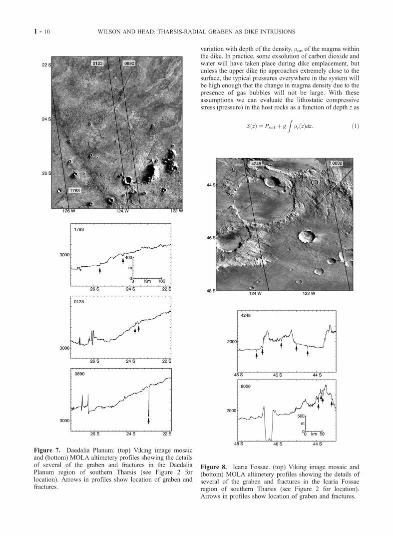
Icaria Fossae Figure 8 MC-24 NE, I-1601 G, F 1–2 100–200 mean spacing is �19 km(9 in �190 km).
Claritas Fossae, Figure 9 MC-17 SE, I-1190 G, F 2–3, largest 6–8 50–100 mean spacing �20 km (13in �260 km)
Thaumasia Fossae, Figure 10 MC-25 NW, I-1263 G 2–4 50–100 mean spacing �18 km (20in �350 km)
WILSON AND HEAD: THARSIS-RADIAL GRABEN AS DIKE INTRUSIONS 1 - 5

Figure 3. Eastern Memnonia Fossae. (top) Viking image mosaic and (bottom) MOLA altimeteryprofiles showing the details of several of the graben and fractures in the Memnonia Fossae region ofsouthern Tharsis (see Figure 2 for location). Arrows in profiles show location of graben and fractures.
1 - 6 WILSON AND HEAD: THARSIS-RADIAL GRABEN AS DIKE INTRUSIONS

purpose can be dealt with by making the depth of pressureequivalence, S, hereafter called the compensation depth, avariable in the analysis and bearing in mind that this depthwill correspond to some unspecified point on the boundaryof the diapir.[15] The dike initially propagates upward buoyantly from
its depth of origin toward the neutral buoyancy level of itsmagma. It increases in width and horizontal extent in themanner modeled by Lister [1990]. On reaching the neutral
buoyancy level it grows upward from, downward from, andlaterally along that level (Figure 11). The excess pressure atthe dike center on the neutral buoyancy level is equal to(�r gS ), where �r is the density difference between themagma and the host rocks averaged over the vertical distanceS and g is the acceleration due to gravity. We show in section4 that S can be as large as 10–20 km on both Mars and Earth,so that if �r is �300 kg m�3, the excess pressure acting onthe dike can be of order 10–20 MPa. Over most of the lateralextent of a giant dike, lateral growth will continue long aftervertical growth has finished [Fialko and Rubin, 1999], andso the stability and location of the final position of the uppertip of the dike will be determined by the static pressureconditions in the vertical direction above the diapir in a wayanalogous to that proposed by Rubin and Pollard [1987] forrift-zone dikes leaving much shallower magma reservoirs inshield volcanoes. The ability of the upper dike tip toapproach the surface is therefore controlled by two require-ments. First, the pressure in the magma at the compensationdepth S must be at least great enough to support the gravita-tional weight of all of the magma above that depth. Second,the stress intensity at the upper tip of the dike must be equalto or greater than the effective fracture toughness of the hostrocks. Pollard [1987] and Rubin [1993b] showed thatfracture toughness is not an inherent material property butis a function of the host rock tensile strength and the dike tipgeometry, including the likely presence of a gas-filled regioninto which magma is too viscous to propagate. At negligibleconfining stresses and in the absence of a gas cavity, K is oforder 3 MPa m1/2 [Rubin, 1993b], whereas Parfitt [1991]found that shallow basaltic dikes, which probably do havegas accumulations in their tips, generally behave as though Khas a value close to 100 MPa m1/2. While the dike is stillgrowing upward, the pressure distribution within it will bepartly controlled by the need to overcome wall friction, andthere will be a relatively low magma pressure just below thedike tip [Rubin, 1993a]. Magmatic volatiles will be exsolvedin this region and will collect into a gas pocket, and so weexpect the effective fracture toughness here to be of order100 MPa m1/2. If the pressure at the compensation depth isgreat enough, the magma column can extend above thesurface. In practice, of course, this means that an eruptionwill occur, with the magma discharge rate being a function ofthe amount by which the compensation pressure exceeds theweight of the magma column. The depth to which the lowertip of the dike will extend also depends on the static stressconditions as the downward growth comes to an end. Anybubbles of gas (actually supercritical fluid) formed by vola-tiles exsolved near the lower tip during the growth phase willtend to drift upward, rather than collect at the lower dike tip,and so we expect the effective fracture toughness at the lowertip to be small; if no exsolved volatile is present, it shouldapproach the theoretical value of zero [Lister, 1990].We haveinvestigated the extent to which our model is sensitive to thevalue assumed and find that the results are indistinguishablefor any value less than a few tens of MPa m1/2.[16] To determine the stress intensities at the dike tips and
the shape of the dike after it reaches a stable vertical profile,we need the detailed variation with depth, z, of the density inthe host rocks, rc, and in the magma, rm. A suitable modelfor the density structure of the Earth’s continental crust isthat developed by W. Mooney et al. (http://ncweb-east.
Figure 4. Western Memnonia Fossae. (top) Viking imagemosaic and (bottom) MOLA altimetery profiles showing thedetails of several of the graben and fractures in theMemnoniaFossae region of southern Tharsis (see Figure 2 for location).Arrows in profiles show location of graben and fractures.
WILSON AND HEAD: THARSIS-RADIAL GRABEN AS DIKE INTRUSIONS 1 - 7

wr.usgs.gov/study/CrustalStructure/crust/,2000) (Figure12a). We have approximated this discrete layer model by amore continuous function defined by contiguous straight linesegments as shown in Figure 12b. Information on the
structure of the interior of Mars derived from tracking themotion of the Mars Global Surveyor spacecraft [Smith et al.,1999; Zuber et al., 2000] suggests a crust with a meandensity of 2900 kg m�3 overlying a mantle with a mean
Figure 5. Sirenum Fossae. (top) Viking image mosaic and (bottom) MOLA altimetery profiles showingthe details of several of the graben and fractures in the Sirenum Fossae region of southern Tharsis (seeFigure 2 for location). Arrows in profiles show location of graben and fractures.
1 - 8 WILSON AND HEAD: THARSIS-RADIAL GRABEN AS DIKE INTRUSIONS

density of 3500 kg m�3. In the region to the south andsouthwest of Tharsis containing the Martian graben studiedhere the crust�mantle boundary is at a depth of about 60 km[Smith et al., 1999; Zuber et al., 2000]. We have taken this
basic information (Figure 12c) and derived from it thesmoother density distribution shown in Figure 12d, basedon the trends of the terrestrial profile. Given the uncertaintiesin the host rock densities, we feel justified in neglecting the
Figure 6. Distal Sirenum Fossae. (top) Viking image mosaic and (bottom) MOLA altimetery profilesshowing the details of several of the graben and fractures in the extreme western portion of SirenumFossae region of southern Tharsis (to the west of the area of Figure 2 and thus not shown there). Arrowsin profiles show location of graben and fractures.
WILSON AND HEAD: THARSIS-RADIAL GRABEN AS DIKE INTRUSIONS 1 - 9
variation with depth of the density, rm, of the magma withinthe dike. In practice, some exsolution of carbon dioxide andwater will have taken place during dike emplacement, butunless the upper dike tip approaches extremely close to thesurface, the typical pressures everywhere in the system willbe high enough that the change in magma density due to thepresence of gas bubbles will not be large. With theseassumptions we can evaluate the lithostatic compressivestress (pressure) in the host rocks as a function of depth z as
S zð Þ ¼ Psurf þ g
Zrc zð Þdz: ð1Þ
Figure 7. Daedalia Planum. (top) Viking image mosaicand (bottom) MOLA altimetery profiles showing the detailsof several of the graben and fractures in the DaedaliaPlanum region of southern Tharsis (see Figure 2 forlocation). Arrows in profiles show location of graben andfractures.
Figure 8. Icaria Fossae. (top) Viking image mosaic and(bottom) MOLA altimetery profiles showing the details ofseveral of the graben and fractures in the Icaria Fossaeregion of southern Tharsis (see Figure 2 for location).Arrows in profiles show location of graben and fractures.
1 - 10 WILSON AND HEAD: THARSIS-RADIAL GRABEN AS DIKE INTRUSIONS

At any chosen compensation depth, C, let the host stress beScomp; then the pressure in the magma at any depth z is
P zð Þ ¼ Scomp � rmg C � zð Þ: ð2Þ
The local driving pressure, Pd, wedging the dike open at anydepth z is then just
Pd zð Þ ¼ P zð Þ � S zð Þ þ T ; ð3Þ
where T is the absolute value of any horizontal regionaltensile stress which may be present in the crust. Banerdt etal. [1992] argue that the range of such stresses for theTharsis region of Mars is likely to span a few tens of Mpa,and so we have used the values 0, 10, 30, and 60 MPa forboth terrestrial and Martian models in what follows.[17] If the dike reaches a stable vertical configuration
with its upper tip at depth U and its lower tip at depth L, thehalf-height of the dike is A = (L � U)/2. The stressintensities at the upper and lower dike tips, Ku and Kl,respectively, are then obtained [Broek, 1974, equation(3.35)] from
Ku ¼ pA1=2� ��1
Zy¼A
y¼�A
Aþ yð Þ= A� yð Þ½ �Pd yð Þdy ð4Þ
and
K1 ¼ pA1=2� ��1
Zy¼A
y¼�A
A� yð Þ= Aþ yð Þ½ �Pd yð Þdy: ð5Þ
Finally, using the model of Rubin and Pollard [1987], if rcuand rcl are the mean density of the host rocks containing theupper and lower halves of the dike, respectively, then themean dike width, W, is given approximately by
W ¼ 1� nð Þ=m½ � p=2ð ÞP0A� g=3ð Þ rm � rcuð Þ þ rcl � rmð Þ½ �A2� �
:
ð6Þ
[18] We implement the model as follows. First, values arechosen for the magma density, rm, and the regional tensilestress, T. Then, a series of values is assumed for the pressurecompensation depth, C. The static height of the magmacolumn which would just be supported by the pressure S(C )is evaluated and compared to C. If the column height isgreater than C, the outcome is noted as a potential eruption;otherwise, the value is stored as the depth of the upper diketip, U. Since the bottom tip of the dike must be located at adepth greater than C, a series of values, L, progressivelygreater than C is taken for the depth of the lower dike tip,and for each of these, equations (4), (5), and (6) are used toevaluate Ku, Kl, and W. When L is just greater than C, Kl isalways positive, but its value decreases as L increases.When Kl reaches some chosen small value, the lower diketip is regarded as having become trapped and the growthprocess is stopped (as noted above, Kl values from zero upto a few tens of MPa m1/2 all lead to similar solutions). Thevalues of Ku and W are then examined. If Ku is greater thanor equal to the critical value representing the effectivefracture toughness (we use 100 MPa m1/2), and if W is
Figure 9. Claritas Fossae. (top) Viking image mosaic and(bottom) MOLA gridded altimetery profiles showing thedetails of several of the graben and fractures in the ClaritasFossae region of southern Tharsis (see Figure 2 forlocation). Arrows in profiles show location of graben andfractures.
WILSON AND HEAD: THARSIS-RADIAL GRABEN AS DIKE INTRUSIONS 1 - 11

positive at all depths, the solution is regarded as physicallypossible and is stored. In other cases, either or both of Ku
and W are negative. These solutions correspond to events inwhich small batches of magma would have pinched off
from the diapir and propagated upward as discrete, detacheddikes as discussed above; such solutions are discarded sincethey do not represent stable giant dikes.
4. Model Results
[19] Using the above analysis, we arrive at a family ofphysically possible giant dikes characterized by three param-eters: the assumed magma density, rm, the depth of pressurecompensation, C, and the regional crustal tensile stress, T.For each such dike our modeling predicts its mean width,W,and the depth to its upper tip, U (or the fact that the tipreaches the surface and an eruption occurs). Figure 13 showsthe details of the relationships for dikes on the Earth in thecase where the regional tension is zero. The magma densitiesused span the entire range between the deep mantle densityand the shallow crustal density. In Figure 13a, mean dikewidth is seen to increase with increasing depth of compen-sation for a given magma density and to decrease withincreasing magma density for a given compensation depth.The boundaries of the parameter space occupied by viablegiant dikes are indicated by dashed lines. As expected, toodeep a compensation depth leads to the generation of a seriesof small buoyant dikes which rise and stall in the crust, andno giant dike can be formed (right-hand side of diagram).Also, the lower the density of the magma, the more readily asurface eruption occurs (upper left part of diagram). Finally,large compensation depths coupled with dense magmas leadto giant dikes which fail to fracture a pathway to as shallow adepth as could be reached on buoyancy grounds alone andare emplaced with a significant excess pressure in their uppertips (bottom middle of diagram). Figure 13b shows the depthto the upper dike tip for the same set of magma densities andcompensation depths as Figure 13a, with the same bounda-ries indicated. The depths to the lower dike tips are notindicated directly in these figures but are generally 1.4–1.6times the corresponding compensation depths.[20] In order to show the influence of the presence of a
regional tectonic tensile stress in a systematic way, Figure 14repeats the information for T = 0 on Earth shown in Figure13 and also gives the results for the three other tensile stressvalues used: 10, 30, and 60 MPa. As before, part a of thefigure shows the mean dike widths, and part b shows thedepths to the upper dike tip. The trends seen in Figure 13 arerepeated but with some systematic changes. As T increases,the range of compensation depths from which giant dikescan be generated decreases, and the sources are required tobe ever closer to the base of the crust. Also as T increases, themean widths of giant dikes increase, and there is a tendencyfor upper dike tips to be located at greater depths below thesurface.[21] Figure 15 shows the complete set of equivalent
results for Martian giant dikes. The variations of mean dikewidth values with rm and T shown in Figure 15a are verysimilar to those of terrestrial giant dikes. However, there is adifference in the trends of depths to upper dike tips betweenFigures 14b and 15b: upper dike tip depths increase with Tthroughout the range of values used for the Earth, but at thelargest tension values on Mars the trend reverses: increasingthe tension further decreases the depth to the upper dike tip,and also (60 MPa panel of Figure 15a) disproportionallyincreases the mean dike width. These differences are the
Figure 10. Thaumasia Fossae. (top) Viking image mosaicand (bottom) MOLA gridded altimetery profiles showingthe details of several of the graben and fractures in theThaumasia Fossae region of southern Tharsis (see Figure 2for location). Arrows in profiles show location of grabenand fractures.
1 - 12 WILSON AND HEAD: THARSIS-RADIAL GRABEN AS DIKE INTRUSIONS

consequence of the nonlinearities introduced by the magmaand rock properties being the same on the two planets,whereas the gravity, and hence all stresses depending ondepth beneath the surface, is systematically smaller onMars.[22] If the whole range of magma densities illustrated
here is actually present (3000–3300 kg m�3 in the case ofMars and 2950–3200 kg m�3 in the case of the Earth), thenon both planets dike widths should commonly be as large as400 m. However, the distributions of dike widths shown inFigures 14 and 15 imply that the average widths of Martiangiant dikes are about 30% greater than those of theirterrestrial counterparts, a trend in the same sense as, butsmaller than, that inferred on the basis of simpler models byWilson and Head [1988], Wilson and Parfitt [1989], andWilson and Head [2000].[23] We noted earlier that the lower tips of the giant dikes
modeled here were located at depths of �1.5 times thecompensation depth. The mean compensation depth onMars is �75 km (Figure 15b) and on Earth is �50 km(Figure 14b). This difference, coupled with the somewhatgreater mean dike width, means that giant dikes on Marswill typically hold almost twice as much magma per unitdistance along strike as dikes on Earth. Also, on bothplanets the entire range of dike widths can be exhibitedby dikes penetrating to very shallow depths in the crust(certainly less than 1500 m on Earth and 2500 m on Mars),thus implying that a very wide range of sizes of surfacegraben could in principle be produced.[24] Figures 14b and 15b show that if magma of a fixed
density is being delivered into a spreading giant dike from adiapir, then if the compensation depth (the effective sourcedepth of the magma) decreases with time the depth to thetop of the dike should increase with time. A trend of veryslightly decreasing compensation depth might be expectedduring a dike emplacement event. This is not because thediapir feeding the dike is ascending as a whole: if the diapirpenetrates the host rocks in a plastic fashion, its mean riserate, based on diapir rise models by Marsh [1982, 1984],
will be less than a meter per year [Wilson et al., 2001].However, the diapir must deform in order to deliver magmainto the dike, and if, as we postulate, there are minimalstresses acting across the boundary between the diapir andits surroundings, this implies that the deep mantle mustaccommodate a deformation regime which allows mantlerocks immediately beneath the diapir to move upward. If thelocation of the main connection between the diapir and thedike is anywhere other than the very top of the diapir,therefore, there will be some small effective upward motionof the source. We show in the next section that the extent ofthis upward motion does not need to be more than a fewkilometers, however, and so we would not expect the depthof the upper dike tip to change by more than a very fewhundred meters. Nevertheless, this might be enough to leadto conditions in which the growing dike initially intersectedthe surface immediately above the diapir, thus leading to aproximal eruption, but ceased to be able to reach the surfaceas it migrated sideways and depleted the diapir, thusforming lateral dikes which had no eruptions from theirdistal portions but nevertheless had associated graben.[25] Ernst et al. [1995, Table 1] found evidence that
members of giant dike swarms on Earth commonly havewidths of �20–60 m, with some values ranging up to �200m. There are no direct methods of measuring the depths ofthe bottoms of these dikes, but indirect methods imply lowerlimits on the depths of 12–20 km. The lower left parts of thepanels in Figure 14a show that dike widths in the 20–60 mrange correspond to those predicted for magmas with den-sities less than about 3000 kg m–3, whereas widths up to 200m imply densities in the 3000–3150 kg m�3 range. Even thesmallest of these widths and densities would require thebottoms of the dikes to penetrate to depths of at least 50 km,implying that the lower limits estimated by existing techni-ques are significant underestimates.[26] We stress that the absolute density values given here
must be viewed with caution: the real control is the differ-ence in density between the magma and the crust. Changes inthe assumed crust-mantle density values, and in the shape of
Figure 11. Diagrammatic representation of a plume rising buoyantly toward the surface in anenvironment of changing rheology and approaching a neutral buoyancy zone.
WILSON AND HEAD: THARSIS-RADIAL GRABEN AS DIKE INTRUSIONS 1 - 13

the density profile, would change the implied magmadensities systematically. However, the degree of conver-gence between our model results and the properties of giantdikes on Earth encourages us to apply the modeling to Mars.
5. Application to Martian Giant Dikes
5.1. Magma Extraction from Mantle Plumes
[27] We expect that, as on Earth, the main sources ofgiant dikes on Mars will be diapirs stalled just below thebase of the crust. We therefore begin by examining the
lower left parts of the panels of Figures 15a and 15b, wherecompensation depths are 60–80 km. Giant dikes canpropagate to shallow levels from these depths for magmadensities up to 3200 kg m�3. These dikes will have meanwidths up to 400 m (Figure 15a). Their tops will be atdepths commonly <3000 m (Figure 15b), and their loweredges will be at depths between 100 and 120 km (about 1.5times the compensation depths). The volumes of such dikeswill depend on the lateral distance that they are able topropagate. We shall shortly infer that graben systems onMars between �1000 and �3000 km in lateral extent are
Figure 12. (a) Model for the density structure of the Earth’s continental crust (W. Mooney et al., http://ncweb-east.wr.usgs.gov/study/CrustalStructure/crust/, 2000). (b) This discrete layer model was approxi-mated by a more continuous function defined by contiguous straight line segments. (c) For the area ofinterest on Mars, the crust-mantle boundary is at a depth of about 60 km [Smith et al., 1999; Zuber et al.,2000]. (d) A smoother density distribution for Mars based on trends in the terrestrial profile.
1 - 14 WILSON AND HEAD: THARSIS-RADIAL GRABEN AS DIKE INTRUSIONS

underlain by giant dikes, and using this distance, we findtotal magma volumes in the dikes of 20,000–60,000 km3.[28] If this magma were derived from a diapiric plume
head with a horizontal diameter of 500 km, then theequivalent vertical extent of the magma in the diapir wouldneed to be �300 m. If this melt were segregated from aresiduum that had undergone 5% partial melting, the orig-inal vertical extent of the zone of partial melting would havehad to be �6 km. Clearly, then, during the lifetime of asingle plume there is no difficulty in accommodating multi-ple episodes of incremental plume rise, partial melting in azone a few kilometers in vertical extent, and melt segrega-tion, followed finally by melt extraction and giant dikeformation. However, an important issue is the fractionalamount of partial melting which must occur in order toinitiate dike propagation, since this, together with the
volume of the plume head, limits the volume of magmaavailable to be injected into the dike. We do not address thisissue in detail but show later in this section that magmacooling limitations imply that a single giant dike may beformed from a series of magma pulses provided that thetotal duration of the episodes is no more than �100 years.[29] The velocity of propagation of a laterally propagat-
ing dike is limited only by the ability of the magma to flowfast enough to keep pace with the elastically advancing tipand is therefore determined by the mean dike width, W, themagma viscosity, h, and the pressure gradient, dP/dz, actingon the magma in the horizontal direction. For a magmadensity close to 3100 kg m�3 (which yields viable dikemodels in Figure 15) the absolute pressure in the magma atthe midpoint of the dike is found in our models to lie in therange 450–550 MPa. If the dike is able to propagate freely,the pressure at the propagating lateral tip will tend to be assmall as possible, which means that it will be buffered bythe exsolution of the least soluble magmatic gas [Lister,1990; Rubin, 1993a]. Data on the solubility of CO2 inmagmas [Harris, 1981; Wilson and Head, 1981] show thatif the magma contains, say, 0.1 wt% CO2, this pressure willbe about 45 MPa. At the beginning of propagation, with thedike tip �250 km (a plausible plume radius) from the centerof the diapir, the pressure difference acting horizontallybetween the magma source and dike tip will be �450 MPa.Rubin [1993a] showed that most of the pressure changealong a propagating dike occurs near the dike tip, and so thetypical pressure gradient acting on the flowing magma willbe dP/dz = �100 Pa m�1; near the end of propagation, withthe tip 3000 km from the source, the gradient will be anorder of magnitude smaller at about 10 Pa m�1. The flowspeed under these conditions of a basaltic magma withviscosity, say, 100 Pa s into a typical giant dike with a meanwidth of �200 m would range from �35 m s�1 initially to�10 m s�1 near the end of dike growth (the magma motionis fully turbulent, and so the exact value of the viscosity isirrelevant). The average of these values corresponds tomagma flowing into the dike at a rate of �1 km3 s�1. Onthe assumption that this rate could be accomplished, theemplacement time of a 3000 km long dike would be oforder 20 hours. We note that the above pressure gradientsand magma flow speeds are very similar to those found byFialko and Rubin [1999] in a more detailed model of lateralmagma flow in giant dikes on Earth. To some extent this isfortuitous, since we are postulating a significantly greaterlevel of neutral magma buoyancy than in their model, suchthat we can neglect contributions to the driving pressuregradient from topographic changes (i.e., lateral changes incrustal thickness) or variations in the vertical gradient of thetectonic stresses along the dike path. However, the similar-ity means that we can draw on some of Fialko and Rubin’s[1999] thermal results. These show not only that magmacooling in dikes of the thicknesses implied by our models isnegligible but also that the amount of heat transferred to thedike walls on the �1 day timescale of emplacement that wefind is not large, not enough to cause significant melting ofdike wall rock, for example. Initial interactions betweenmagma and water or ice in the shallow crust would thereforebe negligible, unless perhaps overpressurized groundwaterwere released by fracturing of a cryospheric seal as a resultof surface deformation [e.g., Head and Wilson, 2002].
Figure 13. (a) Mean widths and (b) depths to upper diketips for giant dikes on Earth as a function of depth of diapirpressure compensation and magma density when theregional tectonic tensile stress is zero. The combinationsof parameters for which giant dikes either cannot form orerupt to the surface are indicated. See text for detaileddiscussion.
WILSON AND HEAD: THARSIS-RADIAL GRABEN AS DIKE INTRUSIONS 1 - 15

[30] These speeds and timescales would, of course, bemaintained only if the diapiric body supplying the magmawere able to deform at the required rate. If the deformationwere accomplished by rise of the mantle rocks beneath thebase of the diapir, the required speed over a circular areawith a radius of 250 km would need to be �4 mm s�1.Whether the Martian mantle can deform at this rate isproblematic, given that typical terrestrial mantle deforma-tion speeds within mantle plumes are �3 10�6 mm s�1;however, presumably the material in the core of a mantleplume from which melt has just been extracted has a smallerbulk viscosity, because of the presence of some residualmelt, than typical mantle rock. We can establish an absoluteminimum required deformation speed by using the magmacooling rate. A thermal cooling wave will penetrate thedistance l = 100 to the center of a 200 m thick dike in a
time of (l2/k) = 1010 s = �330 years. To avoid significantcooling during emplacement, therefore, the minimumemplacement time of such a dike needs to be less than�100 years = �3 109 s. The implied magma supply rateinto the dike is then �2 105 m3 s�1, and the correspond-ing deep mantle deformation speed using the same geom-etry as before is �10�4 mm s�1. This value is closer to, butstill �100 times faster than, normal mantle deformationrates.
5.2. Graben Formation Above Giant Dikes
[31] We now predict the ranges of geometries of thegraben that would be expected to have formed above giantdikes penetrating close to the surface on Mars and comparethese to our observations. Mege and Masson [1996b]discuss at length the various issues which make it difficult
Figure 14. (a) Mean widths and (b) depths to upper dike tips for giant dikes on Earth as a function ofdepth of diapir pressure compensation and magma density for each of four values of the regional crustaltectonic tensile stress.
1 - 16 WILSON AND HEAD: THARSIS-RADIAL GRABEN AS DIKE INTRUSIONS

to establish an unambiguous relationship between thegeometry of a graben and the geometry of, and stressconditions related to, an underlying dike. They give a rangeof possible relationships for graben in the Tharsis regiondetermined from the treatments given by Pollard et al.[1983], Mastin and Pollard [1988], and Rubin and Pollard[1988]. We prefer to use the relationships found by Rubin[1992], who analyzed two dike-induced graben in Icelandusing a model taking account of the inelastic response of thecrust to the fractures forming the graben walls. He foundthat the ratio of the graben width to the depth to the dike topwas a factor of �4 in one case and 2.9 in the other. Weadopt the value 3.5 and note that this ratio is not expected tobe a function of gravity [Rubin, 1992]. Figure 15b showsthat for compensation depths in the upper mantle, dike topdepths commonly range from zero to 3000 m, which wouldimply graben widths up to 10 km. Table 1 shows that all of
the measured graben widths lie in the range 1–4 km,entirely consistent with expectations and implying that theMartian graben were produced as a result of a smaller rangeof conditions than the wide range we have explored in themodeling. Rubin [1992] also found that for his Icelandicexamples the ratio of dike width to amount of verticalsubsidence of the graben floor was 1.0 in one case and1.5 in the other. These values are broadly consistent with theidea that the extension represented by the width of thegraben is approximately equal to the width of the under-lying dike: for graben boundary faults dipping at �60� theratio would be [2 tan 30� =] 1.15. Overall, we adopt thevalue 1.25 as a plausible estimate. The dike widths in Figure15a, commonly in the range 50–500 m, then imply grabensubsidence depths of 40–400 m; Table 1 shows that the vastmajority of unmodified graben depths lie in the range 100–200 m, again consistent with expectations.
Figure 15. (a) Mean widths and (b) depths to upper dike tips for giant dikes on Mars as a function ofdepth of diapir pressure compensation and magma density for each of four values of the regional crustaltectonic tensile stress.
WILSON AND HEAD: THARSIS-RADIAL GRABEN AS DIKE INTRUSIONS 1 - 17

[32] Table 2 summarizes the predicted dike and grabengeometries derived from the theoretical model. As anillustration of the more detailed inferences that may bemade from these results, we note, for example, that theupper limit to graben width of 4 km shown in Table 1corresponds to a depth to dike top of no more than �1500m, and Figure 15b implies that the simplest explanation isthat the dike magmas involved had densities less than�3200 kg m–3. Similarly, the common maximum grabendepth of 200 m corresponds to a dike width of �250 m, andFigure 15a shows that if the regional tensional stress isgreater than about 30 MPa, the dike width can be less than�250 m only if the magma density is greater than �3200kg m�3. This is in direct conflict with the inference that themagma density be less than 3200 kg m�3 just obtainedfrom the graben widths, and so we conclude that regionaltensional stress levels in the Tharsis province were gener-ally less than �30 MPa when the giant dikes wereemplaced.[33] Next we note that it is rare for eruptions to be
associated with the graben studied here. Figure 15b showsthat to ensure that the upper dike tip does not reach thesurface, we require a magma density greater than �3100 kgm�3 if the regional tension is 30 MPa, greater than �3150kg m�3 if the regional tension is 10 MPa, and greater than�3200 kg m�3 if the regional tension is 30 MPa. But wehave already concluded that the regional tension must beless than �30 MPa and that the magma density must be lessthan �3200 kg m�3. Thus we infer that various combina-tions of magma density in the range 3100–3200 kg m�3
and regional tension between zero and 30 MPa are con-sistent with the general absence of eruptions. We stress here,as for the terrestrial examples given earlier, that these valueswould change somewhat if the density structure of thelithosphere were different from the model adopted. How-ever, they are certainly robust enough to indicate the broadconditions required for the formation of the featuresobserved.[34] Finally, we explore the consequences of intruding
giant dikes into a Martian crustal structure different fromthat underlying Tharsis. The equivalent of the calculationsdescribed above was carried out with the depth assumed forthe crust-mantle boundary changed from 60 to 40 km, avalue more appropriate for the northern lowlands on Mars[Zuber et al., 2000]. The shape of the density profile shownin Figure 12d was retained; that is, we simply scaled all ofthe depths to 2/3 of their original values. The results showthe following patterns: (1) The range of depths below thecrust-mantle boundary from which viable giant dikes can beproduced is reduced to �65% of its previous value; (2) thedepths to dike tops for a given magma density are also
reduced to �65% of their previous values; (3) the meandike widths for a given magma density are reduced to�50% of their previous values; (4) to generate a given dikewidth and depth to dike top for the same distance of thecompensation depth below the crust-mantle boundaryrequires a denser magma; and (5) if we wished to ensurethat generally eruption-free graben with the widths anddepths found in the Tharsis systems were also created inthese thinner crustal conditions, then the restrictions onregional tensional stress would be similar to before, withvalues less than �30 MPa being relevant, but the restric-tions on magma density would be much tighter, with onlyvalues close to 3100 kg m�3 being allowed. The implica-tion is that for a similar spread of magma densities,eruptions from giant dikes would be more likely to occurin regions where the crust was thinner.
6. Discussion and Implications
[35] This analysis illustrates that the vast Tharsis-radialgraben and fracture systems are plausibly interpreted asgiant radiating dike systems emanating from the central partof Tharsis and forming dike complexes whose verticalextents span the majority of the crust and extend into themantle. On the basis of these findings we address severalimplications and outline areas of further study.
6.1. Origin and Orientation of Radial Structures
[36] On the basis of geological relationships described insection 2, the extensive graben in the southern Tharsisregion (Figures 1 and 2) appear to radiate from two differentcenters, Arsia Mons and Syria Planum. It is highly likelythat these two edifices represent the surface manifestation ofascending plumes. As we have shown above, the size andgeometry of the radial graben are consistent with an originby radial dike emplacement from plumes rising below ArsiaMons and Syria Planum, development of near-surfacestresses during dike emplacement, and faulting to producethe fractures and graben.[37] Graben systems are commonly not purely radial to
their source edifices, but they can clearly be traced back tothe interpreted source region. This is typical of radial dikesystems as they propagate outward from regions character-ized by the source-controlled, overpressure-dominatedproximal stress field to distal regions where the regionalstress field dominates [e.g., Pollard, 1987; Grosfils andHead, 1994a, 1994b; Ernst et al., 1995]. A corollary is thatthe longer dikes emplaced during buffered magma supplyconditions [Parfitt and Head, 1993] are more likely to bearcuate than shorter dikes that are emplaced in unbufferedmagma supply conditions. Because dikes can become
Table 2. Parameters of Giant Dikes and Associated Graben Systems on Marsa
Horizontal RegionalTensile Stress, Mpa
Range of Depths FromWhich Dikes CanPropagate, km
Depths of UpperDike Tips, km
Mean DikeWidths, m
Implied Range ofGraben Widths, km
Implied Range ofGraben Depths, m
0 60–110 0–3.0 0–420 0–9.5 0–33510 60–95 0–3.8 0–500 0–13.3 0–40030 60–85 0–5.7 80–620 0–20 65–50060 60–70 0–3.6 460–850 0–12.6 370–680
aThe maximum ranges of values are given; see text for discussion of most likely values.
1 - 18 WILSON AND HEAD: THARSIS-RADIAL GRABEN AS DIKE INTRUSIONS

increasingly nonradial with distance from the source, wecaution that multiple lines of evidence must be employed inorder to locate source regions of dike-induced graben whereonly parts of the system are preserved [Anderson et al.,1998; Anderson and Dohm, 2000; Dohm et al., 2000;Anderson et al., 2001].[38] In the case of the graben mapped in this analysis
(Figures 1 and 2), stereographic reprojection (Figure 16)shows that they are generally radial to the centers in Arsiaand Syria and do not show the major distal deviation oftenseen in the other examples cited above. This is very likelydue to the fact that stresses are concentrated at the advanc-ing dike tip which lies at the neutral buoyancy zone at thebase of the crust, and thus the surface orientation is not verysusceptible to shallower stresses concentrated in the uppercrust (though there is some influence of shallow stresses,evidenced by the presence of en echelon offsets betweensome graben segments: Figures 3–10). This, together withthe minimal regional stresses apparently necessary forgraben formation over dikes, appears to account for thedominantly radial trends out to great distances from thesource region.
6.2. Timing of Radial Structures
[39] The range of tectonic and volcanic activity associ-ated with Tharsis spans from the Noachian to Amazonianperiods [Scott and Tanaka, 1986; Tanaka et al., 1992], andit is anticipated that radial dike systems were emplacedthroughout this period, as suggested by the stratigraphicrelationships between the structures [e.g., Watters andMaxwell, 1983]. In principle, giant radial dikes are verylikely to be linked to periods of enhanced magma produc-tion and supply (buffered conditions [e.g., Parfitt and Head,1993]), which are most likely to occur in the initial periodsof plume penetration and flattening or at times of subse-quent peak supply (e.g., during episodic pulses in plume tailflow). For the Arsia Mons examples, it is clear from thestratigraphic relationships that radial graben occurred duringthe early, middle, and late stages in the formation of Arsiabut that the longest graben were concentrated in the earlierstages of evolution. For the Syria-radial systems, grabenformation was concentrated in the early to intermediateperiods, and there is little evidence for Amazonian-agedactivity.
6.3. Volume of Magma Intruded in Different Eventsand Implications for Magma Reservoirs and MagmaSupply
[40] Wilson et al. [2001] have shown that the volumesand estimated total lifetimes of the Tharsis volcanoes implythat they were each built with a mean magma supply rate of�0.05 m3 s�1. Summit caldera morphologies and positionsindicate that multiple magma reservoirs existed at slightlydifferent places at different times [Scott and Wilson, 2000]and thus that temporal gaps existed between periods ofmagma supply. Magma supply rates to establish newreservoirs are estimated by Wilson et al. [2001] to be�1–10 m3 s�1 for periods of 100,000 years, with an initialpulse of more than 150 m3 s�1 over at least a few weeksrequired for reservoir initiation. Wilson et al. [2001] exam-ined volumes of long flows on Tharsis and concluded thatthey must represent eruption rates of �100–300 m3 s�1 that
occurred for periods of a few to tens of years, implyingbuffered eruption conditions [Parfitt and Head, 1993] inwhich a high magma supply rate from the mantle iscontinuously maintained, in contrast to unbuffered condi-tions characterizing smaller-volume inelastic caldera col-lapse events. These relationships suggested to Wilson et al.[2001] that the Tharsis volcanoes were built episodically;active phases lasting between 1 and 10 Myr alternated withquiescent periods of �10–100 Myr. Ten to perhaps as manyas a hundred cycles of enhanced magma supply may havebeen involved.[41] The individual dike emplacement events modeled
here and interpreted to underlie the radial graben are of themagnitude and frequency that are also typical of bufferedmagma supply situations, in which a high magma supplyrate from the mantle is continuously maintained [Parfitt andHead, 1993]. For example, a circumferential traversearound the Arsia-centered radial graben reveals about 30parallel graben, while a similar traverse around the SyriaPlanum-centered graben shows at least 50 structures(Figure 2). Thus these features may be a record of thebuffered events that initiate new phases of magmatic activ-ity in the Tharsis volcanoes. Closer examination of theircrosscutting stratigraphic relationships with underlyingunits, as well as their grouping, could provide more detailedevidence about the history of magma supply in the Tharsisvolcanoes and also about the state and orientation of litho-spheric stress at those times. The number and impliedfrequency of these major events can be understood in termsof instabilities in the extraction of melt from mantle plumeheads in general [Scott and Stevenson, 1986; White et al.,1995] and on Mars in particular [e.g., Harder, 1998, 2000].[42] Although volcanic edifices, particularly those on
Tharsis, are visually impressive in terms of their magnitude,detailed analyses have shown that a significantly largerportion of a magmatic event is intrusive, rather thanextrusive [Crisp, 1984], and this is particularly true in termsof the presence of extensive radial dike swarms. Forexample, the volume of the Arsia Mons edifice is estimatedto be �1.5 106 km3 [Smith et al., 2001]. Estimates of thevolume of magma in one major diking event calculated hererange from 20 to 60 103 km3, which is 1–4% of the totalvolume of the edifice.
6.4. Number of Events in Individual Systems andImplications for Regional Strain
[43] Golombek et al. [1996] measured the amount ofextension across Tempe Terra by examining fault scarpwidths and deformed craters. Measurements of fault scarpwidth and slopes for simple graben and rifts were used toestimate fault throw, and these data, together with estimatesof fault dips, were used to estimate extension. Golombek etal. [1996] found about 2–3% strain across the Tempe Terraregion, in a direction normal to the radially orientedstructures. The two methods indicated an average extensionfor single normal fault scarps of �100 m. Golombek et al.[1996] point out that estimates elsewhere around Tharsisshow significant differences (Thaumasia �0.5%; Sirenum,0.1%) although strain across individual structures withsmaller widths can be much higher (5–20%). Our calcu-lations show that a significant amount of the observed straincould be the result of dike emplacement, in which vertical
WILSON AND HEAD: THARSIS-RADIAL GRABEN AS DIKE INTRUSIONS 1 - 19

overpressurized magma-filled cracks tens to hundreds ofmeters in width create extensional stresses resulting in near-surface fissures and graben.
6.5. Influence of Giant Dike Emplacement on theCryosphere and Hydrosphere
[44] Emplacement of dikes of this magnitude must havean influence on various aspects of the geological evolutionof the substrate. Emplacement may be rapid enough (hoursto days) that the initial heat pulse is likely to have a minimaleffect on the environment. However, as soon as emplace-ment is complete, the dike represents a vertical thermalanomaly that spans virtually the entire hydrosphere andcryosphere. Its presence should set up heating of thesurrounding groundwater system and produce extensivehydrothermal circulation over the course of its coolinghistory [McKenzie and Nimmo, 1999]. Dikes with thetypical widths found here will take several tens of yearsto cool conductively [Wilson and Head, 1994], and coolingrate will be enhanced by recirculating groundwater. Onemight expect significant deposition of hydrothermal miner-
als in the vicinity of the margins of the dike and perhaps assurface deposits in the vicinity above the dike associatedwith the graben and fractures [e.g., Gulick, 1998]. Further-more, if the near-surface stresses associated with dikeemplacement crack the cryosphere, such buoyantly risinghot water might form hot springs and surface hydrothermaldeposits in the vicinity. If the cryosphere has sealed thegroundwater system under hydrostatic pressure prior to dikeemplacement, then fracturing associated with dike emplace-ment may crack the cryospheric seal, leading to the cata-strophic release of groundwater. Such a situation isenvisioned to have occurred in the case of Mangala Valles,in the northern part of Memnonia Fossae, where Mangalaemerges from one of the graben in the system (Figure 17)[see Head and Wilson, 2002, and references therein].
6.6. Influence of Giant Dikes on Groundwater Flow
[45] Examination of Figure 2 shows that the formation ofsuch significant dikes in the crust could have a major effecton regional and global groundwater circulation. Clifford[1993] describes a north-south global circulation of ground-
Figure 16. Distribution of graben and fracture systems in southern Tharsis. Dark lines radial to Tharsisshow locations of graben and fracture systems mapped at 1:15 million scale in Figure 2. This figure isFigure 2 reprojected in stereographic projection centered on Arsia Mons (9�S, 120�W). Note the radialnature of the graben systems. Stars indicate location of summits of Arsia Mons (left) and Syria Planum(right) edifices, to which most of the structures are radial.
1 - 20 WILSON AND HEAD: THARSIS-RADIAL GRABEN AS DIKE INTRUSIONS

water that is a fundamental part of the hydrological cycle.Groundwater migrating from the higher south polar regionwould encounter a series of candidate groundwater barriersin the form of the vertical dike sequences. This could serveto channel groundwater toward the eastern part of Tharsis inthis area and potentially influence or contribute to anabundance of groundwater in this area. Carr [1979, 1996]has pointed out that overpressure of a groundwater systembeneath a cryospheric cap in this area could be responsiblefor the catastrophic outflow channels [see also Head andWilson, 2002].
6.7. Gas Exsolution from Giant Dikes
[46] The great width of a giant dike could also lead toconvection within the dike while it was cooling. Theresulting vertical recycling of magma would enhance gas
exsolution and gas loss. This could result in gas pressurebuildup, leakage, and collapse to form craters over the dikeand within the graben. It could also lead to vulcanianeruptions, such as those envisioned in some dark halodeposits on the Moon [e.g., Head et al., 2002a], wheregas buildup creates overpressures that cause catastrophicdisruption of the lid, or even more prolonged plinianeruptions, as suggested for some large elongate cratersassociated with graben near Alba Patera on Mars [Scott etal., 2002; Scott and Wilson, 2002]. In any case, if all of thegas estimated to occur in Martian basalts degasses from thedike, it would contribute about 0.1% of the total volatilesthought to be contributed by the volume of early Hesperianextrusive lavas represented by the ridged plains [e.g., Headet al., 2002b].
6.8. Eruptions Along Giant Dikes and the Origin ofPlains
[47] The laterally (along-strike) irregular and discontin-uous occurrence of graben and fractures indicates that thetops of the dikes are not necessarily at the same depth alongtheir total length. Differences in surface topography, andlocal and regional geology and stresses, could also causesuch irregular distribution. As a result, surface eruptionsmight be expected to occur at some locations along thestrike of the dike but not necessarily everywhere. Theseeruptions would tend to form flood deposits and plains, notsmall edifices characterized by multiple, low-volume erup-tions. Other than pits and depressions locally enlarged bycollapse, positive edifices and volcanic landforms are notclearly associated with the graben and fractures. Scott[1980, 1982] has mapped a number of features that mightbe candidates, but a clear association has not been firmlyestablished. One possible manifestation of surface eruptionscould be the distribution of volcanic plains in regionsassociated with the graben. At least part of the along-strikeirregularities could be due to surface effusion and burial ofthe graben. Analysis of the geological maps [Scott andTanaka, 1986] shows that there are often patches of Noa-chian and Hesperian plains that could overlie and obscuresome of the graben and fractures and represent localizedsurface eruptions.
6.9. Variations in Crustal Thickness and Implicationsfor Resurfacing of the Northern Lowlands
[48] If giant dikes are intruded into a Martian crustalstructure different from that underlying Tharsis (�60 km)and more like that of the northern lowlands (�40 km) [e.g.,Zuber et al., 2000], we find that for a similar spread ofmagma densities, eruptions from giant dikes would be morelikely to occur in regions where the crust was thinner.Recent analyses of the stratigraphy of the northern lowlandshas documented the likely presence of widespread depositsof Early Hesperian ridged plains (Hr) of volcanic origin[Head et al., 2002b]. No specific source edifices have beendocumented within the northern lowlands, but our findingssuggest that radial dikes from nearby sources in the adjacentuplands (e.g., Tharsis, Tempe Fossae, Alba Patera, Elysium,etc.) could easily reach into all parts of the northern low-lands and produce eruptions to provide the resurfacing thatapparently occurred in the Early Hesperian, prior to theemplacement of the Vastitas Borealis Formation [e.g., Head
Figure 17. Memnonia Fossae and Mangala Valles, show-ing the interpreted relation of graben, dikes, and outflowchannels. (a) The Memnonia Fossae graben extend from theTharsis rise, and Mangala Valles appears to have its sourceat one of the Memnonia graben. (b) One explanation for thisrelationship is shown in the block diagram, where dikes areseen to propagate radially from overpressurized magmareservoirs in Tharsis. As the dikes approach the surface,they create near-surface stress fields that form graben,cracking the cryosphere and releasing groundwater confinedby the cryosphere. Outflow continues until the cryospherefreezes and reseals or hydrostatic equilibrium is reached.
WILSON AND HEAD: THARSIS-RADIAL GRABEN AS DIKE INTRUSIONS 1 - 21

et al., 2002b]. Reduction in magma density favors eruptioneven further. If the basaltic andesite compositions in thenorthern lowlands interpreted from Thermal Emission Spec-trometer (TES) data [Bandfield et al., 2000; Christensen etal., 2000] represent the underlying rock composition (seealso discussion by Noble and Pieters [2001]), then densitymay have been an additional factor and may imply differentcompositions in the northern plume sources from those inthe south of Tharsis.
6.10. Implications for Linear Magnetic Anomalies
[49] We note that some of the magnetic lineationsrecently observed on Mars [Acuna et al., 1999; Connerneyet al., 1999; Purucker et al., 2000] have dimensions similarto those of the dike systems described here and aresubparallel to them. Dike intrusion has been proposed as apossible cause of such lineations [e.g., Wilson and Head,2000; Nimmo, 2000], but further study is needed to deter-mine if this specific mechanism is applicable. An outstand-ing question is related to timing. If the magnetic dynamo onMars is limited to its earliest history, primarily duringcrustal formation (see summary by Stevenson [2001]), thenthis largely predates the observed surface geological recordand the features described in this paper almost certainlypostdate this period. However, if the initiation of Tharsisaccompanied or overlapped with initial crustal formation[e.g., Phillips et al., 2001], these linear magnetic anomaliescould be related to earlier dike intrusion phases not cur-rently preserved in surface deformation.
6.11. Implications for Models for the Origin andEvolution of Tharsis
[50] The origin of Tharsis and the relationships betweenits volcanic and tectonic features have been a matter ofcontroversy for years (see summaries by Banerdt et al.[1992] and Tanaka et al. [1991]). Numerous models havebeen proposed to explain the observed topography, gravity,and stress state, including that Tharsis is a huge uplifteddome [e.g., Phillips et al., 1973; Mege and Masson, 1996b],that it formed isostatically by magmatic intrusion [e.g., Sleepand Phillips, 1979, 1985], and that it formed primarily byvolcanic loading [e.g., Solomon and Head, 1982]. Recentgravity and topography data from MGS have shown thatloading of the lithosphere by the Tharsis rise in the Noachiancan explain much of the global shape and long-wavelengthgravity field of Mars [e.g., Phillips et al., 2001].[51] The radial graben discussed in this paper (Figures 1
and 2) form an important part of the observational con-straints for models of the origin of Tharsis [e.g., Banerdt etal., 1992; Tanaka et al., 1991]. The interpretation of thesefeatures as the surface manifestation of large dikes emplacedradially from magmatic centers in Tharsis removes the needto call on Tharsis-related regional extensional stresses fortheir formation, although such regional stresses could aid intheir formation and orientation. Similarly, regional strainmeasurements made from analysis of the offset on theseradial features should be considered in the context of strainassociated with dike emplacement and not solely regionaltectonic strain associated with the evolution of Tharsis.Finally, the timing of formation of these features should beconsidered in the context of both tectonic and magmaticmodels. Tectonic models often call on time-dependent
stresses associated with, for example, uplift or loading toproduce the radial graben. Magmatic models such as the oneoutlined here produce the graben from stresses associatedwith plume and reservoir overpressurization and lateralpropagation of magma-filled cracks. Thus the graben areassociated primarily with magmatic history and can form atany time throughout the history of the plumes. The range ofages of the radial graben described in section 2 lends supportto the magmatic models.[52] The magmatic interpretation of the Tharsis-radial
graben potentially removes one of the conundrums ofTharsis tectonics [e.g., Banerdt and Golombek, 2000], inwhich it appeared to be necessary to require two distinctmodes of support for Tharsis in order to explain thepresence of radial structures (graben) on both the elevatedflanks (where they were attributed to isostatic stresses) andoutside the Tharsis topographic rise (where they were seento be more consistent with flexure).
[53] Acknowledgments. Thanks are extended to Steve Pratt forassistance in creating the images, to Anne Cote for drafting, to NancyCarroll and Elizabeth Fuller for help in manuscript preparation, to Eve Scottand Benjamin Webb for productive discussions, and to Eric Grosfils andRichard Ernst for very helpful reviews. This research was supported bygrants to J.W.H. from the NASA Planetary Geology and GeophysicsProgram and the Mars Data Analysis Program and to L.W. from the U.K.Particle Physics and Astronomy Research Council, all of which are grate-fully acknowledged.
ReferencesAcuna, M. H., et al., Global distribution of crustal magnetization discoveredby the Mars Global Surveyor MAG/ER Experiment, Science, 284, 790–793, 1999.
Anderson, R. C., and J. M. Dohm, Magmatic-tectonic evolution of Tharsis(abstract), Lunar Planet. Sci. [CD-ROM], XXXI, abstract 1607, 2000.
Anderson, R. C., et al., Centers of tectonic activity through time for thewestern hemisphere of Mars, Lunar Planet Sci. [CD-ROM], XXIX, ab-stract 1881, 1998.
Anderson, R. C., J. M. Dohm, M. P. Golombek, A. F. C. Haldemann, B. J.Franklin, K. L. Tanaka, J. Lias, and B. Peer, Primary centers and sec-ondary concentrations of tectonic activity through time in the westernhemisphere of Mars, J. Geophys. Res., 106, 20,563–20,585, 2001.
Bandfield, J. L., V. E. Hamilton, and P. R. Christensen, A global view ofMartian surface compositions from MGS-TES, Science, 287, 1626–1630, 2000.
Banerdt, W. B., and M. P. Golombek, Long-wavelength stress models forMars: New and improved, Lunar Planet. Sci., XX, 40–41, 1989.
Banerdt, W. B., and M. P. Golombek, Tectonics of the Tharsis region ofMars: Insights from MGS topography and gravity (abstract), Lunar Pla-net. Sci. [CD-ROM], XXXI, abstract 2038, 2000.
Banerdt, W. B., R. J. Phillips, N. H. Sleep, and R. S. Saunders, Thick shelltectonics on one-plate planets: Applications to Mars, J. Geophys. Res.,87, 9723–9733, 1982.
Banerdt, W. B., M. P. Golombek, and K. L. Tanaka, Stress and tectonics onMars, inMars, edited by H. H. Kieffer et al., chap. 8, pp. 249–297, Univ.of Ariz. Press, Tucson, 1992.
Broek, D., Elementary Fracture Mechanics, 408 pp., Noordhoff, Leyden,1974.
Carr, M. H., Formation of Martian flood features by release of water fromcontined aquiffers, J. Geophys. Res., 84, 2995–3007, 1979.
Carr, M. H., Water on Mars, 229 pp., Oxford Univ. Press, New York, 1996.Christensen, P. R., J. L. Bandfield, M. D. Smith, V. E. Hamilton, and R. N.Clark, Identification of a basaltic component of the Martian surface fromThermal Emission Spectrometer data, J. Geophys. Res., 105, 9609–9621,2000.
Clifford, S., A model for the hydrologic and climatic behavior of water onMars, J. Geophys. Res., 98, 10,973–11,016, 1993.
Connerney, J. E. P., M. H. Acuna, P. J. Wasilewski, N. F. Ness, H. Reme, C.Mazelle, D. Vignes, R. P. Lin, D. L. Mitchell, and P. A. Cloutier, Mag-netic lineations in the ancient crust of Mars, Science, 284, 794–798,1999.
Crisp, J., Rates of magma emplacement and volcanic output, J. Volcanol.Geotherm. Res., 20, 177–211, 1984.
1 - 22 WILSON AND HEAD: THARSIS-RADIAL GRABEN AS DIKE INTRUSIONS

Cyr, K. E., and H. J. Melosh, Tectonic patterns and regional stresses nearVenusian coronae, Icarus, 102, 175–184, 1993.
Davis, P. A., Discontinuities in the shallow Martian crust at Lunae, Syria,and Sinai Plana, J. Geophys. Res., 95, 14,231–14,248, 1990.
Dohm, J. M., R. C. Anderson, V. R. Baker, R. G. Strom, G. Komatsu, andT. M. Hare, Pulses of magmatic activity through time: Potential triggersfor climatic variations on Mars (abstract), Lunar Planet. Sci. [CD–ROM], XXXI, abstract 1632, 2000.
Ernst, R. E., and W. R. A. Barager, Evidence from magnetic fabric for theflow pattern of magma in the MacKenzie giant radiating dyke swarm,Nature, 356, 511–513, 1992.
Ernst, R. E., J. W. Head, E. Parfitt, E. Grosfils, and L. Wilson, Giant radiat-ing dyke swarms on Earth and Venus, Earth Sci. Rev., 39, 1–58, 1995.
Ernst, R. E., E. Grosfils, and D. Mege, Giant dyke swarms: Earth, Venusand Mars, Annu. Rev. Earth Planet. Sci., 29, 489–534, 2001.
Fahrig, W. F., and T. D. West, Diabase dyke swarms of the Canadian shield,Map 1627A, Geol. Surv. of Can., Ottawa, Ontario, Canada, 1986.
Fialko, Y. A., and A. M. Rubin, Thermal and mechanical aspects of magmaemplacement in giant dike swarms, J. Geophys. Res., 104, 23,033–23,049, 1999.
Frey, H., Thaumasia: A fossilized early forming Tharsis uplift, J. Geophys.Res., 84, 1009–1023, 1979.
Golombek, M. P., and R. J. Phillips, Tharsis fault sequence as a test of adeformation mechanism (abstract), Lunar Planet. Sci., XIV, 253–254,1983.
Golombek, M. P., K. L. Tanaka, and B. J. Franklin, Extension across TempeTerra, Mars, from measurements of fault scarp widths and deformedcraters, J. Geophys. Res., 101, 26,119–26,130, 1996.
Greeley, R., and J. E. Guest, Geologic map of the eastern equatorial regionof Mars, U.S. Geol. Surv. Misc. Invest. Ser.Map, I-1802-B, scale1:15,000, 000, 1987.
Grosfils, E. B., and J. W. Head, Emplacement of a radiating dike swam inwestern Vinmara Planitia, Venus: Interpretation of the regional stress fieldorientation and subsurface magmatic configuration, Earth Moon Planets,66, 153–171, 1994a.
Grosfils, E. B., and J. W. Head, The global distribution of giant radiatingdike swarms on Venus: Implications for the global stress state, Geophy-sical Res. Lett., 21, 701–704, 1994b.
Grosfils, E. B., and J. W. Head, Radiating dike swarms on Venus: Evidencefor emplacement at zones of neutral buoyancy, Planet. Space Sci., 43,1555–1560, 1995.
Gulick, V. C., Magmatic intrusions and a hydrothermal origin for fluvialvalleys on Mars, J. Geophys. Res., 103, 19,365–19,388, 1998.
Harder, H., Phase transitions and the 3D planform of thermal convection inthe Martian mantle, J. Geophys. Res., 103, 16,775–16,797, 1998.
Harder, H., Mantle convection and the dynamic geoid of Mars, Geophys.Res. Lett., 27, 301–304, 2000.
Harris, D. M., The concentration of CO2 in submarine tholeiitic basalts, J.Geol., 89, 689–701, 1981.
Head, J., and L. Wilson, Lunar mare volcanism: Stratigraphy, eruptionconditions, and the evolution of secondary crusts, Geochim. Cosmochim.Acta, 56, 2155, 1992.
Head, J., and L. Wilson, Lunar graben formation due to near-surface de-formation accompanying dike emplacement, Planet. Space Sci., 41(10),719–727, 1993.
Head, J. W., and L. Wilson, Mars: General environments and geologicalsettings of magma/H2O interactions, Volcano-Ice Interaction on Earthand Mars, Geol. Soc. Spec. Publ., in press, 2002.
Head, J. W., L. Wilson, and C. M. Weitz, Dark ring in southwestern lunarOrientale basin: Origin as a single pyroclastic eruption, J. Geophys. Res.,107(E1), 10.1029/2000JE001438, 2002a.
Head, J. W., M. A. Kreslavsky, and S. Pratt, Northern lowlands of Mars:Evidence for widespread volcanic flooding and tectonic deformation inthe Hesperian Period, J. Geophys. Res. , 107(E1), 10.1029/2000JE001445, 2002b.
Lister, J. R., Buoyancy-driven fluid fracture: Similarity solutions for thevertical and horizontal propagation of fluid-filled cracks, J. Fluid Mech.,217, 213–239, 1990.
Maaloe, S., and A. Scheie, The permeability controlled accumulation ofprimary magma, Contrib. Mineral. Petrol., 81, 350–357, 1982.
Marsh, B. D., On the mechanics of igneous diapirism, stoping, and zonemelting, Am. J. Sci., 282, 808–855, 1982.
Marsh, B. D., Mechanics and energetics of magma formation and ascension,in Explosive Volcanism: Inception, Evolution, and Hazards, edited by F.R. Boyd Jr., pp. 67–83, Natl. Acad. Press, Washington, D. C., 1984.
Mastin, L. G., and D. D. Pollard, Surface deformation and shallow dikeintrusion processes at Inyo Craters, Long Valley, California, J. Geophys.Res., 93, 13,221–13,235, 1988.
McGarr, A., On the state of lithospheric stress in the absence of appliedtectonic forces, J. Geophys. Res., 93(B11), 13,609–13,617, 1988.
McKenzie, D., The extraction of magma from the crust and mantle, EarthPlanet. Sci. Lett., 74, 81–91, 1985.
McKenzie, D., and F. Nimmo, The generation of Martian floods by themelting of ground ice above dykes, Nature, 397, 231–233, 1999.
Mege, D., and P. Masson, Stress models for Tharsis formation, Mars,Planet. Space Sci., 44, 1471–1497, 1996a.
Mege, D., and P. Masson, A plume tectonics model for the Tharsis pro-vince, Mars, Planet. Space Sci., 44, 1499–1546, 1996b.
Nimmo, F., Dike intrusion as a possible cause of linear Martian magneticanomalies, Geology, 28, 391–394, 2000.
Noble, S. K., and C. M. Pieters, Type 2 terrain: Compositional constraintson the Martian lowlands, Lunar Planet. Sci. [CD-ROM], XXXII, abstract1230, 2001.
Parfitt, E. A., The role of rift zone storage in controlling the site and timingof eruptions and intrusions at Kilauea volcano, Hawaii, J. Geophys. Res.,96, 10,101–10,112, 1991.
Parfitt, E. A., and J. W. Head, Buffered and unbuffered dike emplacementon Earth and Venus: Implications for magma reservoir size, depth, andrate of magma replenishment, Earth Moon Planets, 61, 249–261, 1993.
Phillips, R. J., R. S. Saunders, and J. E. Conel, Mars: Crustal structureinferred from Bouguer gravity anomalies, J. Geophys. Res., 78, 4815–4820, 1973.
Phillips, R. J., et al., Ancient geodynamics and global-scale hydrology onMars, Science, 291, 2587–2591, 2001.
Plescia, J. B., and R. S. Saunders, Tectonic history of the Tharsis region,Mars, J. Geophys. Res., 87, 9775–9791, 1982.
Pollard, D. D., Elementary fracture mechanics applied to the structuralinterpretation of dikes, in Mafic Dyke Swarms, edited by H. C. Hallsand W. F. Fahrig, Geol. Soc. Can. Spec. Pap. 34, 5–24, 1987.
Pollard, D. D., P. T. Delaney, W. A. Duffield, E. T. Endo, and A. T.Okamura, Surface deformation in volcanic rift zones, Tectonophysics,94, 541–584, 1983.
Purucker, M., D. Ravat, H. Frey, C. Voorhies, T. Sabaka, and M. Acuna, Analtitude-normalized magnetic map of Mars and its interpretation, Geo-phys. Res. Lett., 27, 2449–2452, 2000.
Rubin, A. M., Dike-induced faulting and graben subsidence in volcanic riftzones, J. Geophys. Res., 97, 1839–1858, 1992.
Rubin, A. M., Dikes vs. diapirs in viscoelastic rock, Earth Planet. Sci. Lett.,119, 641–659, 1993a.
Rubin, A. M., Tensile fracture of rock at high confining pressure: Implica-tions for dike propagation, J. Geophys. Res., 98, 15,919–15,935, 1993b.
Rubin, A. M., and D. D. Pollard, Origin of blade-like dikes in volcanic riftzones, in Volcanism in Hawaii, edited by R. W. Decker, T. L. Wright, andP. H. Stauffer, U.S. Geol. Surv. Prof. Pap.,1350, 1449–1470, 1987.
Rubin, A. M., and D. D. Pollard, Dike-induced faulting in rift zones ofIceland and Afar, Geology, 16, 413–417, 1988.
Scott, D. H., Mars Tharsis region: Volcanotectonic events in the strati-graphic record, Proc. Lunar Planet. Sci. Conf., 11th, 2403–2421, 1980.
Scott, D. H., Volcanoes and volcanic provinces: Martian western hemi-sphere, J. Geophys. Res., 87, 9839–9851, 1982.
Scott, D. H., and K. L. Tanaka, Geologic map of the western equatorialregion of Mars, U.S. Geol. Surv. Misc. Invest. Ser.Map, I-1802-A, scale1:15,000,000, 1986.
Scott, D. R., and D. J. Stevenson, Magma ascent by porous flow, J. Geo-phys. Res., 91, 9283–9296, 1986.
Scott, E. D., and L. Wilson, Cyclical summit collapse events at AscraeusMons, Mars, J. Geol. Soc. London, 157, 1101–1106, 2000.
Scott, E. D., and L. Wilson, Plinian eruptions and passive collapse events asthe mechanism of formation of Martian pit chain craters, J. Geophys.Res., 107, 10.1029/2000JE001432, in press, 2002.
Scott, E. D., L. Wilson, and J. W. Head, Emplacement of giant radial dikesin the Tharsis region of Mars, J. Geophys. Res., 107, 10.1029/2000JE001431, in press, 2002.
Sleep, N. H., and R. J. Phillips, An isostatic model for the Tharsis province,Mars, Geophys. Res. Lett., 6, 803–806, 1979.
Sleep, N. H., and R. J. Phillips, Gravity and lithospheric stress on theterrestrial planets with emphasis on the Tharsis region of Mars, J. Geo-phys. Res., 90, 4469–4489, 1985.
Smith, D. E., W. L. Sjogren, G. L. Tyler, G. Balmino, F. G. Lemoine, andA. S. Konopliv, The gravity field of Mars: Results from Mars GlobalSurveyor, Science, 286, 94–96, 1999.
Smith, D. E., et al., Mars Orbiter Laser Altimeter (MOLA): Experimentsummary after the first year of global mapping of Mars, J. Geophys. Res.,106, 23,689–23,722, 2001.
Solomon, S. C., and J. W. Head, Evolution of the Tharsis province of Mars:The importance of heterogeneous lithospheric thickness and volcanicconstruction, J. Geophys. Res., 87, 9755–9774, 1982.
Stevenson, D. J., Mars’ core and magnetism, Nature, 412, 214–219, 2001.Tanaka, K. L., and P. A. Davis, Tectonic history of the Syria Planumprovince of Mars, J. Geophys. Res., 93, 14,893–14,917, 1988.
WILSON AND HEAD: THARSIS-RADIAL GRABEN AS DIKE INTRUSIONS 1 - 23

Tanaka, K. L., and M. P. Golombek, Martian tension fractures and theformation of grabens and collapse features at Valles Marineris, Proc.Lunar Planet. Sci. Conf.19th, 383–396, 1989.
Tanaka, K. L., M. P. Golombek, and W. B. Banerdt, Reconciliation of stressand structural histories of the Tharsis region, Mars, J. Geophys. Res., 96,15,617–15,633, 1991.
Tanaka, K. L., D. H. Scott, and R. Greeley, Global stratigraphy, in Mars,edited by H. H. Kieffer et al., pp. 345–382, Univ. of Ariz. Press, Tucson,1992.
Watters, T. R., and T. A. Maxwell, Crosscutting relations and relative agesof ridges and faults in the Tharsis region of Mars, Icarus, 56, 278–298,1983.
White, R. S., J. W. Brown, and J. R. Smallwood, The temperature of theIceland plume and origin of outward-propagating v-shaped ridges, J.Geol. Soc. London, 152, 1039–1045, 1995.
Wilson, L., and J. W. Head, Ascent and eruption of basaltic magma on theEarth and Moon, J. Geophys. Res., 86, 2971–3001, 1981.
Wilson, L., and J. W. Head, The influence of gravity on planetary volcaniceruption rates, Lunar Planet. Sci., 19, 1283–1284, 1988.
Wilson, L., and J. W. Head, Mars: Review and analysis of voclanic eurptiontheory and relationships to observed landforms, Rev. Geohys., 32, 221–264, 1994.
Wilson, L., and J. W. Head, Tharsis– radial graben systems as the surfacemanifestation of plume-related dike intrusion complexes: Models and
implications, Lunar Planet. Sci. Conf. [CD-ROM], XXXI, abstract1371, 2000.
Wilson, L., and E. A. Parfitt, The influence of gravity on planetary eruptionrates: A reappraisal, Lunar Planet. Sci., XX, 1213–1214, 1989.
Wilson, L., E. D. Scott, and J. W. Head, Evidence for episodicity in themagma supply to the large Tharsis volcanoes, J. Geophys. Res., 106,1423–1433, 2001.
Wise, D. U., M. P. Golombek, and G. E. McGill, Tectonic evolution ofMars, J. Geophys. Res., 84, 7934–7939, 1979a.
Wise, D. U., M. P. Golombek, and G. E. McGill, Tharsis province of Mars:Geologic sequence, geometry, and a deformation mechanism, Icarus, 38,456–472, 1979b.
Zuber, M., et al., Internal structure and early thermal evolution of Marsfrom Mars Global Surveyor topography and gravity, Science, 287, 1788–1793, 2000.
�����������J. W. Head III, Department of Geological Sciences, Brown University,
Providence, RI 02912, USA. ([email protected])L. Wilson, Environmental Sciences Department, Lancaster University,
Lancaster LA1 4YQ, UK. ([email protected])
1 - 24 WILSON AND HEAD: THARSIS-RADIAL GRABEN AS DIKE INTRUSIONS