Embed Size (px)
Citation preview

Thammasat International Journal of Science and Technology Vol. 19, No. 1 , January-March 2014
* Correspondence : [email protected]
A Dynamic Model and Control Strategy
for the Combined Multipulse Multilevel
Converter Based HVDC System
B. Geethalakshmi *
Department of EEE, Pondicherry Engineering College, Pondicherry, India
Abstract
The multipulse multilevel converter topology is a newly introduced converter
topology with the potential for high voltage direct current (HVDC) transmission applications.
This paper focuses on harmonic reduction, control and design of multipulse multilevel
converters for the realization of HVDC systems. Dynamic performance of the proposed
converter based HVDC system with nominal power of 100 MW and voltage of 33 kV, 50 Hz
is evaluated in the MATLAB/Simulink environment. The simulation results show that with
the proposed converter topology and control strategy used, the HVDC station can respond
satisfactorily to the system dynamics and control commands under steady state and dynamic
load conditions while maintaining voltage balance of the DC capacitors.
Keywords : HVDC system, multipulse converter, multilevel inverter, total harmonic
distortion, voltage source converter. 1. Introduction
The availability of high power, high
frequency semiconductor switches with the
gate turn off capability has made the
implementation of high power voltage
source converters (VSC) possible for utility
applications including high voltage direct
current (HVDC) systems [1-4]. The VSC
based HVDC transmission system shown in
Fig.1 has been widely accepted for either
back-to-back or point-to-point bulk power
transmission. The conventional 6-pulse
converter suffers from relatively high input
harmonic current when used as a rectifier
and high output voltage harmonics when
operated as an inverter. In response to the
growing demands for high power converter
units, multipulse converters (MPC) have
drawn increased interest in the field of
research and industry [5]–[8]. An MPC
generates a waveform which closely
resembles a sine wave by connecting a
number of identical three-phase converter
bridges through phase shifting transformers
(PST). The key problem with multipulse
converter is the requirement of magnetic
interfaces constituted by complex zigzag
phase shifting transformers which increases
the cost of the complete system [5].
Recently, HVDC converter systems
using full back-to-back multilevel diode-
clamped converters are investigated, owing
to their high-voltage, high-current and
staircase-like waveform capabilities [9].
Hence an attractive alternative to the
multipulse converter is the multilevel
converter (MLC) [10]-[12]. In multilevel
converters, a premium quality output
waveform can be achieved with a
sufficiently high number of voltage levels.
However, the number of voltage levels is
limited due to control complexity and cost.
Additionally, a large number of DC
capacitors

Thammasat International Journal of Science and Technology Vol. 19, No. 1 , January-March 2014
16
are required. The voltages of these
capacitors must be balanced in order to
avoid over-voltages on any particular link.
A critical review of literature shows neither
multipulse converters nor multilevel
converters are useful on their own. A hybrid
converter topology incorporating the
advantages of both MPC and MLC will be
attractive [13].
The main objective of this paper is to
develop a multipulse multilevel converter
topology and to use it for the realization of a
back-to-back connected HVDC system. The
harmonic performance of this converter
topology as rectifier for AC to DC
conversion and as an a inverter for DC to
AC conversion is evaluated through
MATLAB based simulation. Addionally,
the paper investigates the behaviour of the
proposed HVDC system under
comprehensive scenarios such as steady
state conditions and dynamic conditions for
converter stations operating with a single
frequency and stations with different
frequencies.
2. Converter station operating as a
rectifier The three phase fully controlled
VSC shown in Fig. 2 has probably been the
most widely used power electronic
converter in the medium to high power
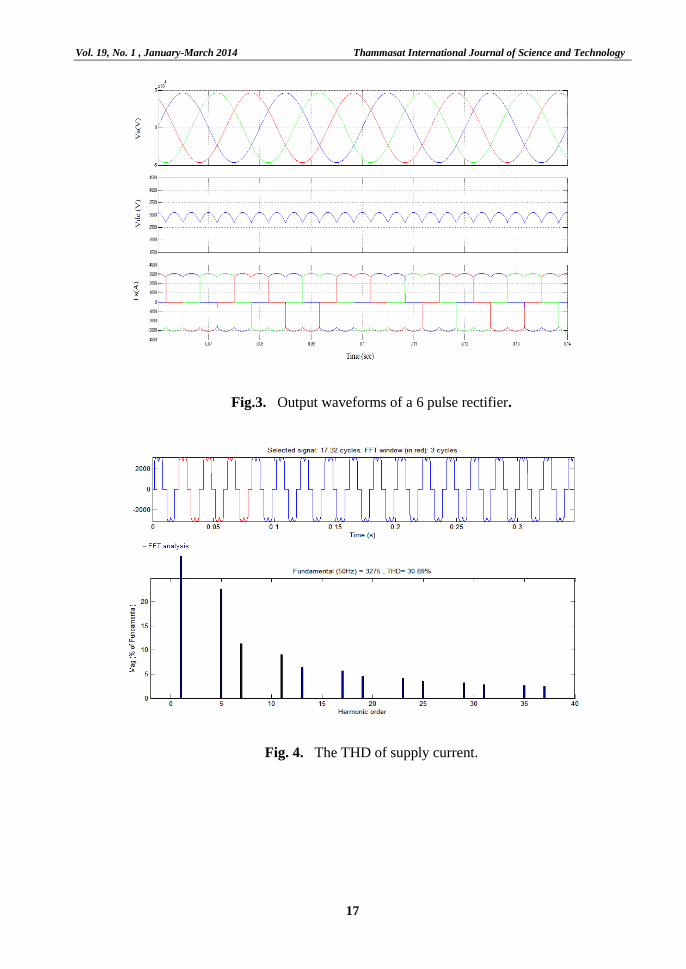
applications. Fig. 3 shows the output voltage
and the supply current waveform of a fully
controlled 6 pulse rectifier. Although it is
the simplest configuration, it suffers from a
relatively high value of harmonic
components in the input current which in
turn amounts to the high value of total
harmonic distortion (THD) of 30.69% as
depicted in Fig.4.
Fig .1. A Schematic diagram of an HVDC system.
Fig .2. A fully controlled 6 pulse VSC.
Vol. 19, No. 1 , January-March 2014 Thammasat International Journal of Science and Technology
17
Fig.3. Output waveforms of a 6 pulse rectifier.
Fig. 4. The THD of supply current.

Thammasat International Journal of Science and Technology Vol. 19, No. 1 , January-March 2014
18
In order to overcome this drawback
one of the solutions is to go for multipulse
converters. For an n-pulse converter, the
characteristic harmonics are of the order of
nk ± 1 where k = 1, 2, 3, …∞.
The higher the pulse number, the lower the
order of input current harmonics, lower the
ripple content on the DC voltage and the
higher the ripple frequency will be. Four
basic 6-pulse converters as depicted in Fig.5
are connected in parallel with an appropriate
phase shift to achieve a 24-pulse converter
operation. The phase shift is designed so as
to make the transformer construction
identical. The transformer turns ratio is
chosen according to the DC link voltage
requirement. Fig.6 shows the transformer
connections used to realize a 24-pulse
voltage source converter. The phase
displacement pattern is shown below in
Table 1.A phase shift of ±7.5° is introduced
by the phase shifting transformer in the
input AC supply in order to have a phase
shift of 15° between two adjacent converter
inputs and the corresponding phase shift of
±7.5°, -22.5º and -37.5 º are introduced in
the gating circuits of the 6 pulse converters.
Fig .4. 24 Pulse converter operated as a
rectifier.
Fig .5. Transformer connections.
The 24 pulse DC output voltage
resulting from the cascading of four fully
controlled converters with an appropriate
phase shift between them is shown in Fig.7.
Furthermore, this figure depicts the
elimination of lower order harmonics in the
supply current resulting in a sinusoidal
waveform. The lowest order harmonics
present in the supply current are the 23rd
and
25th.These values are typical of a 24- pulse
system. This is highlighted in Fig. 8 and
results in a total harmonic distortion of
1.1%. Thus, with a 24- pulse converter, the
supply current THD is significantly reduced
without any filtering equipment. The
multiplication of the pulse number helps in
the elimination of the input current
harmonics and the reduction of ripple
content in the DC link voltage. This ensures
that the converter that has been developed
could very well be employed for an efficient
modeling of a HVDC system.
Vol. 19, No. 1 , January-March 2014 Thammasat International Journal of Science and Technology
19
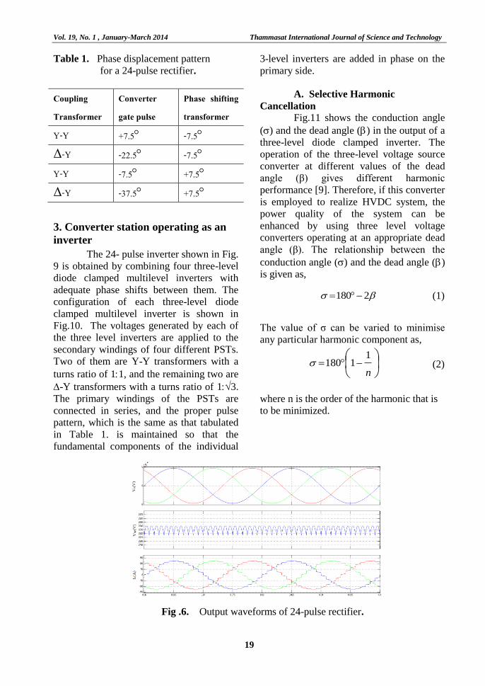
Table 1. Phase displacement pattern
for a 24-pulse rectifier.
Coupling Transformer
Converter gate pulse
Phase shifting transformer
Y-Y +7.5 -7.5 Δ-Y -22.5 -7.5
Y-Y -7.5 +7.5 Δ-Y -37.5 +7.5 3. Converter station operating as an
inverter
The 24- pulse inverter shown in Fig.
9 is obtained by combining four three-level
diode clamped multilevel inverters with
adequate phase shifts between them. The
configuration of each three-level diode
clamped multilevel inverter is shown in
Fig.10. The voltages generated by each of
the three level inverters are applied to the
secondary windings of four different PSTs.
Two of them are Y-Y transformers with a
turns ratio of 11, and the remaining two are
-Y transformers with a turns ratio of 13.
The primary windings of the PSTs are
connected in series, and the proper pulse
pattern, which is the same as that tabulated
in Table 1. is maintained so that the
fundamental components of the individual
3-level inverters are added in phase on the
primary side.
A. Selective Harmonic
Cancellation
Fig.11 shows the conduction angle
() and the dead angle () in the output of a
three-level diode clamped inverter. The
operation of the three-level voltage source
converter at different values of the dead
angle (β) gives different harmonic
performance [9]. Therefore, if this converter
is employed to realize HVDC system, the
power quality of the system can be
enhanced by using three level voltage
converters operating at an appropriate dead
angle (β). The relationship between the
conduction angle () and the dead angle ()
is given as,
2180 (1)
The value of σ can be varied to minimise
any particular harmonic component as,
n
11180 (2)
where n is the order of the harmonic that is
to be minimized.
Fig .6. Output waveforms of 24-pulse rectifier.
Thammasat International Journal of Science and Technology Vol. 19, No. 1 , January-March 2014
20
Fig .7. THD of the supply current.
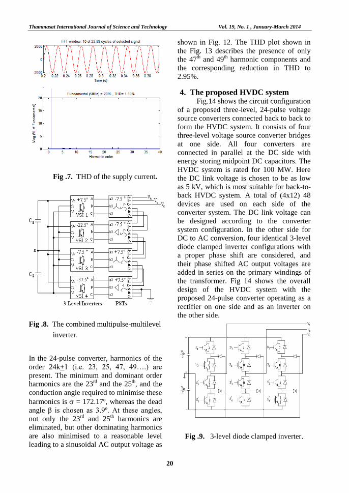
Fig .8. The combined multipulse-multilevel
inverter. In the 24-pulse converter, harmonics of the
order 24k+1 (i.e. 23, 25, 47, 49….) are
present. The minimum and dominant order
harmonics are the 23rd
and the 25th, and the
conduction angle required to minimise these
harmonics is = 172.17º, whereas the dead
angle β is chosen as 3.9º. At these angles,
not only the 23rd
and 25th harmonics are
eliminated, but other dominating harmonics
are also minimised to a reasonable level
leading to a sinusoidal AC output voltage as
shown in Fig. 12. The THD plot shown in
the Fig. 13 describes the presence of only
the 47th and 49
th harmonic components and
the corresponding reduction in THD to
2.95%.
4. The proposed HVDC system
Fig.14 shows the circuit configuration
of a proposed three-level, 24-pulse voltage
source converters connected back to back to
form the HVDC system. It consists of four
three-level voltage source converter bridges
at one side. All four converters are
connected in parallel at the DC side with
energy storing midpoint DC capacitors. The
HVDC system is rated for 100 MW. Here
the DC link voltage is chosen to be as low
as 5 kV, which is most suitable for back-to-
back HVDC system. A total of (4x12) 48
devices are used on each side of the
converter system. The DC link voltage can
be designed according to the converter
system configuration. In the other side for
DC to AC conversion, four identical 3-level
diode clamped inverter configurations with
a proper phase shift are considered, and
their phase shifted AC output voltages are
added in series on the primary windings of
the transformer. Fig 14 shows the overall
design of the HVDC system with the
proposed 24-pulse converter operating as a
rectifier on one side and as an inverter on
the other side.
Fig .9. 3-level diode clamped inverter.

Vol. 19, No. 1 , January-March 2014 Thammasat International Journal of Science and Technology
21
Fig .10. 3-level diode clamped inverter
output voltage.
Fig .11. Output voltage of the 24-pulse
inverter.
Fig .12. Output voltage THD.
5. Open loop operation
The proposed multipulse multilevel
converter based HVDC transmission is
realized in the MATLAB / Simulink
environment, and the corresponding
simulink model for open loop operation is
shown in Fig. 15. The parameters used for
the simulation are given in Table 2.
The HVDC transmission system
consists of two stations. One station acts as
a 24-pulse rectifier, and the other acts as a
24-pulse inverter. Thus, the AC voltage in
station 1 is converted to DC through the
rectifier. Power transmitted as DC power
and the DC is converted to the required AC
voltage of station 2 through the inverter.
The waveforms of the converter station 1
voltages and currents, The DC link Voltage,
the DC link current, the converter station2
voltages and currents are demonstrated in
Fig. 16 for the load variations given at
t=0.3s and t = 0.5s, respectively. Upon the
addition of load, there is a dip in the DC
voltage. As a consequence of this, the grid
voltage decreases, an outcome which is not
acceptable. For the above reasons, we
choose closed loop control, ensuring that a
constant DC voltage is maintained
irrespective of the load variations.
6. Closed loop control
The coordinated control of two
converter stations is the heart of the HVDC
system for dynamic control of the active and
reactive power. The closed loop control
scheme is developed from a mathematical
model of the VSC- HVDC system.

Thammasat International Journal of Science and Technology Vol. 19, No. 1 , January-March 2014
22
Fig .13. 24-pulse voltage source converter based HVDC system configuration.
Fig .14. Open loop simulink model of HVDC system.
Fig .15. Waveforms for stations with the same frequency.

Vol. 19, No. 1 , January-March 2014 Thammasat International Journal of Science and Technology
23
Table 2. Design Parameters. Parameter Symbol Value
Rated active power P 100MW
Supply voltage Vs / Vr 33kV
Frequency f1 / f2 50Hz / 50Hz
AC inductance L1 / L2 6.9mH/ 6.9mH
DC link voltage Vdc 5 kV
DC link capacitance Cdc 0.125 mF
Resistance R 0.015Ω/km
Transformer power rating VI t 100 MVA
Transformation Ratio n ¼
Transformer Voltage V primary / V secondary 33 kV / 2.1kV
Transformer inductance L 5mH
A. Dynamic Model of VSC-HVDC
The AC-to-DC 24-pulse converter
model is depicted in Fig.17. The system
consists of four 6-pulse converters. The DC-
side of the 24-pulse converter is composed
of two identical capacitors. All the losses in
the 24-pulse converter and transformer are
represented by an equivalent resistance R,
while the transformer inductance is
represented by an equivalent inductance L.
For simplicity, the following assumptions
are made:
1) The system parameters and the
system voltages are three phase balanced.
2) The power switches, diodes and
passive components of four 6-pulse
converters are correspondingly identical.
The equations governing the instantaneous
values of the three-phase voltages across the
supply side of the rectifier and the current
flowing into it are given by
sc
sb
sa
mc
mb
ma
sc
sb
sa
sc
sb
sa
v
v
v
v
v
v
Li
i
i
L
RL
RL
R
dt
didt
didt
di
1
00
00
00 (3)
where is is the supply current
Since the system is assumed to be a
balanced one, it can be transformed into a
synchronous d- q-o frame by applying
Park’s transformation.
sqmq
sdmd
sq
sd
sq
sd
vv
vv
Li
i
L
RL
R
dt
didt
di
1
(4)
where is the synchronous angular speed
of the network voltage.The power balance
equation between the dc and ac terminals of
the converter is

Thammasat International Journal of Science and Technology Vol. 19, No. 1 , January-March 2014
24
sqsqsdsddcdc IVIVIVP
2
3 (5)
Because of the 24-pulse configuration, all
the harmonics produced in the supply
current is of the converter are cancelled, and
the equation relating the DC side and AC
side can be written as
cosdcsd kVV (6)
sindcsq kVV (7)
where
sd
sq
V
V1tan is the angle
between the converter voltage and the
system voltage; k is the ratio between the
AC and DC voltage of the inverter; and Vdc
is the DC link voltage. Substituting Vsd and
Vsq in equation (5), we obtain
sddcsddcdc
dc
sqsddc
IkVIkVdt
dvC
IIk
I
sincos2
3
sincos2
3
(8)
sddcsddc
dc
dc IkVIkVc
k
dt
dv sincos
2
3 (9)
With equations (4) and (9), the complete
system equation could be expressed in a
matrix form as given in equation (10):
0
1
0sin2
3cos
2
3
sin
cos
mq
md
dc
sq
sd
dcdc
dc
sq
sd
V
V
Lv
i
i
c
k
c
kL
k
L
RL
k
L
R
dt
dvdt
didt
di
(10)
Using equation (10), the reference input to
the PWM modulator is derived as follows:
dt
dI
sdsqmdsdsdLRIILVV (11)
dt
dI
sqsdmqsq
sqLRIILVV (12)
Equations (11) and (12) are realized to
establish the 24-pulse converter operation in
the closed loop control scheme.
Fig .16. Equivalent circuit of AC-to-DC
conversion.
B. Control Strategy
A complete closed loop control
scheme for operating the 24-pulse rectifier
with the unity power factor on the input side
is shown in Fig.18. The objective of the
control loop is to maintain the DC voltage at
the desired reference value and to control
the active power flow from AC grid to the
DC side. A set of capacitors are used at the
DC bus to support the dc link voltage at the
desired value to make the real power
balance between the two sides of the
converter. This is the most important for a
successful operation of the HVDC system.
It requires two control loops namely the
outer voltage control loop and the inner
current control loop. The outer DC voltage
controller sets the real current reference for
the inner current controller. The reactive
current reference is set to zero for achieving
the unity power factor. In the inner current
controller, a decoupled current control
strategy is employed in order to
independently control the real and the
reactive power components.
A phase-locked loop is used to
determine the instantaneous angle θ of the
three-phase line voltage. The three-phase
voltages and the supply currents are
transformed into two-phase quantities using
Park’s transformation, which gives d – q
axis voltage and current for the controller.
The d-axis reference current isd* obtained
from the DC voltage controller is compared
Vol. 19, No. 1 , January-March 2014 Thammasat International Journal of Science and Technology
25
with the actual d axis current and is
stabilized through the PI controller to get
the equivalent d axis reference voltage.
Similarly, the actual q axis current iq is
compared with the reference current isq*
which is set to zero for achieving the unity
power factor, and the error so obtained is
stabilized through another PI controller to
get the equivalent q axis reference voltage.
The parameters of these PI controllers are
tuned, and their values are tabulated in
Table 3. Further more, the equations (11)
and (12) are realized in the inner current
control loop in order to obtain the reference
wave for the PWM modulator.
Fig .17. Closed loop control scheme.
Table 3. PI controller parameters.
PI controller KP KI
PI1 0.5 2.5
PI2 1.8 6
PI3 7 4.3
7. Simulation results and discussion
In this section, the behaviour of the
VSC-based HVDC transmission system will
be analyzed using MATLAB/Simulink.
Thus, in order to test the closed loop control
scheme and to test the behaviour of the
system, suitable case studies are carried out
under steady state and dynamic operation.
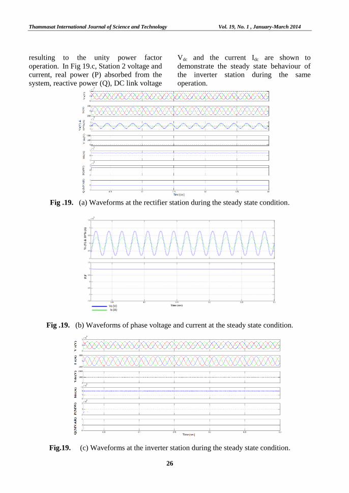
A. Steady State Condition A constant power is made to flow
from one station to the other, and the
behaviour of the system is demonstrated in
Fig 19. The reference real power command
is set at 100MW and reactive power is
maintained at zero throughout the steady-
state operation. In Fig 19.a, Station 1
voltage and current, real power (P) supplied
to the system, reactive power (Q), DC link
voltage Vdc, and the current through the DC
link are shown to demonstrate the behaviour
of the rectifier during the steady state
operation of the VSC based HVDC systems.
The relation between the phase voltage and
phase current is separately highlighted in
Fig 19.b to show that they are in phase with
each other
Thammasat International Journal of Science and Technology Vol. 19, No. 1 , January-March 2014
26
resulting to the unity power factor
operation. In Fig 19.c, Station 2 voltage and
current, real power (P) absorbed from the
system, reactive power (Q), DC link voltage
Vdc and the current Idc are shown to
demonstrate the steady state behaviour of
the inverter station during the same
operation.
Fig .19. (a) Waveforms at the rectifier station during the steady state condition.
Fig .19. (b) Waveforms of phase voltage and current at the steady state condition.
Fig.19. (c) Waveforms at the inverter station during the steady state condition.
Vol. 19, No. 1 , January-March 2014 Thammasat International Journal of Science and Technology
27
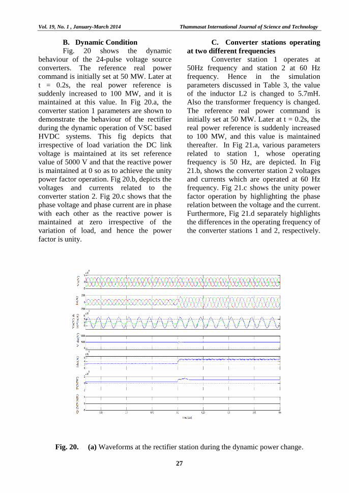
B. Dynamic Condition
Fig. 20 shows the dynamic
behaviour of the 24-pulse voltage source
converters. The reference real power
command is initially set at 50 MW. Later at
t = 0.2s, the real power reference is
suddenly increased to 100 MW, and it is
maintained at this value. In Fig 20.a, the
converter station 1 parameters are shown to
demonstrate the behaviour of the rectifier
during the dynamic operation of VSC based
HVDC systems. This fig depicts that
irrespective of load variation the DC link
voltage is maintained at its set reference
value of 5000 V and that the reactive power
is maintained at 0 so as to achieve the unity
power factor operation. Fig 20.b, depicts the
voltages and currents related to the
converter station 2. Fig 20.c shows that the
phase voltage and phase current are in phase
with each other as the reactive power is
maintained at zero irrespective of the
variation of load, and hence the power
factor is unity.
C. Converter stations operating
at two different frequencies
Converter station 1 operates at
50Hz frequency and station 2 at 60 Hz
frequency. Hence in the simulation
parameters discussed in Table 3, the value
of the inductor L2 is changed to 5.7mH.
Also the transformer frequency is changed.
The reference real power command is
initially set at 50 MW. Later at t = 0.2s, the
real power reference is suddenly increased
to 100 MW, and this value is maintained
thereafter. In Fig 21.a, various parameters
related to station 1, whose operating
frequency is 50 Hz, are depicted. In Fig
21.b, shows the converter station 2 voltages
and currents which are operated at 60 Hz
frequency. Fig 21.c shows the unity power
factor operation by highlighting the phase
relation between the voltage and the current.
Furthermore, Fig 21.d separately highlights
the differences in the operating frequency of
the converter stations 1 and 2, respectively.
Fig. 20. (a) Waveforms at the rectifier station during the dynamic power change.

Thammasat International Journal of Science and Technology Vol. 19, No. 1 , January-March 2014
28
Fig .20. (b)Waveforms at the inverter station during the dynamic power change.
Fig. 20. (c)Waveforms of phase voltage and current during the dynamic condition.
Fig .21. (a) Waveforms at the station 1 for systems operating with two different frequencies.

Vol. 19, No. 1 , January-March 2014 Thammasat International Journal of Science and Technology
29
Fig. 21. (b) Waveforms at the station 2 for systems operating with two different frequencies.
Fig. 21. (c) Waveforms of phase voltage and current for systems with different frequencies.
Fig .21. (d) Converter station 1 and 2 voltages at different frequencies.
Thammasat International Journal of Science and Technology Vol. 19, No. 1 , January-March 2014
30
8. Conclusion
The application of power
electronics started with the emergence of
high voltage direct current system. Although
HVDC was a feasible solution for efficient
long distance bulk power transmission,
accompanying harmonic currents had
been a great challenge. Hence in the
present work, the design of a rectifier and in
inverter for a significant reduction of
harmonics has been done. For the
elimination of harmonics of supply
current, a 24-pulse rectifier based on a
star-connected transformer has been
designed. The analysis of the proposed
inverter obtained by combining the
multipulse-multilevel inverter topologies
shows that there is a drastic reduction in
total harmonic distortion. A proper
selection of the dead angle for a multi
level inverter, in the combined topology
would yield better harmonic performance.
The closed loop controller based on
decoupled control strategy has been
developed and found to be effective over
a wide range of power system operating
conditions. The behaviour of the proposed
24-pulse VSC based HVDC system has
been analyzed under steady state dynamic
operating conditions for stations with a
single frequency and stations with
different frequencies. The steady state and
dynamic performances describes the ability
of a control algorithm for a successful
operation of the proposed converter in a
HVDC system.
9. Acknowledgement
I would like to convey my thanks to
my students Ms. A. Arthi and Mr.R.Dinesh
for the help they rendered in developing the
simulation of the proposed system.
10. References
[1] AmirnaserYazdani and Reza Iravani,
“Dynamic model and control of the
NPC – Based Back –to – Back
HVDC system”, IEEE Transactions
on Power Delivery, Vol. 21, No.1,
pp.414 – 424, Jan. 2006.
[2] Jiangchao Qin and Maryam
Saeedifard, “Predictive control of a
modular multilevel converter for a
back – to- back HVDC system”,
IEEE Transactions on Power
Delivery, Vol. 27, No. 3, pp.1538 –
1547, July 2012.
[3] Maryam Saeedifard and Reza Iravani,
“Dynamic performance of a modular
multilevel back-to-back HVDC
system, IEEE Transactions on Power
Delivery”, Vol. 25, No. 4, pp.2903 –
2912, October 2010.
[4] Flourentzou N., Agelidis V.,
Demetriades G., “VSC-based HVDC
power transmissionSystems: An
overview, IEEE Transactions on
Power Electronics”, Vol. 24, No.3,
pp.592-602, 2009.
[5] Diego Soto and Tim.C. Green, “A
comparison of High-Power Converter
Topologies for the implementation of
FACTS Controllers”, IEEE
Transactions on Industrial
Electronics, vol.49, 2002, pp.1072-
1080.
[6] Bhim Singh, G. Bhuvaneswari and
VipinGarg, “Harmonic mitigation
using 12-pulse ac-dc converter in
Vector Controlled Induction Motor
Drives”, IEEE Transactions on Power
Delivery, Vol.21, No.3, 2006, 1483-
1492.
[7] Ricardo Davalos M., Juan M.
Ramirez and O. Ruben Tapia,
“Three-phase multi-pulse converter
STATCOM analysis”, Electric
Power and Energy Systems, Vol.27,
pp.39-51, 2005.
Vol. 19, No. 1 , January-March 2014 Thammasat International Journal of Science and Technology
31
[8] D. Madhan Mohan, B. Singh and
B.K. Panigrahi,“Harmonic optimised
24 – pulse voltage source converter
for high voltage DC systems”, IET
Power Electronics, Vol. 2, Issue 5,
pp. 563 – 573, 2009.
[9] M. Chaves, E.Margati, J.F. Silva and
S.F. Pinto, “New approach in back-
to-back m-level diode-clamped
multilevel converter modelling and
direct current bus voltages balancing,
IET Power Electronics”, Vol. 3, Issue
4, pp.578 – 589, 2010.
[10] J.S.Lai and F.Z.Peng, “Multilevel
converters – A new breed of power
converters, IEEE Transactions on
Industrial Applications”, Vol.32,
pp.509-517, 1996.
[11] F.G.Peng and J.S.Lai, “Multilevel
cascade voltage source inverter with
separate dc sources”, U.S. Patent 5
642 275, 1997.
[12] J. Rodriguez, J.S.Lai and F.Z.Peng,
“Multilevel inverters: A survey of
topologies, controls and
applications”, IEEE Transactions on
Industrial Electronics, vol.49, no.4,
2002, 724-738.
[13] B. Geethalakshmi and P. Dananjayan,
“A Combined Multipulse-Multilevel
Inverter Suitable For High Power
Applications”, International Journal
of Computer and Electrical
Engineering, Vol. 2, No. 2, pp.1793-
8163, April, 2010.