Embed Size (px)
Citation preview

TEXAS INSTRUMENTS ANALOG UNIVERSITY PROGRAM DESIGN CONTEST MIXED‐SIGNAL TEST INTERFACE
CHRISTOPHER EDMONDS, DANIEL KEESE, RICHARD PRZYBYLA SCHOOL OF ELECTRICAL ENGINEERING AND COMPUTER SCIENCE
OREGON STATE UNIVERSITY
Edmonds, Keese, Przybyla
2 of 12
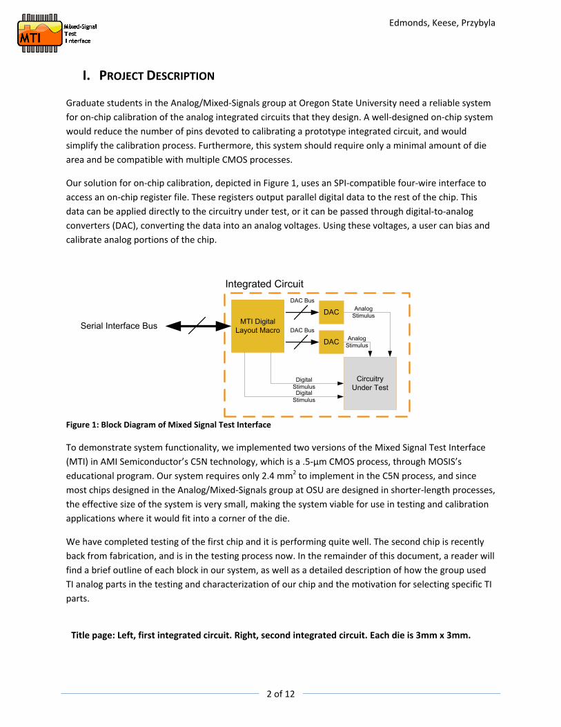
I. PROJECT DESCRIPTION Graduate students in the Analog/Mixed‐Signals group at Oregon State University need a reliable system for on‐chip calibration of the analog integrated circuits that they design. A well‐designed on‐chip system would reduce the number of pins devoted to calibrating a prototype integrated circuit, and would simplify the calibration process. Furthermore, this system should require only a minimal amount of die area and be compatible with multiple CMOS processes.
Our solution for on‐chip calibration, depicted in Figure 1, uses an SPI‐compatible four‐wire interface to access an on‐chip register file. These registers output parallel digital data to the rest of the chip. This data can be applied directly to the circuitry under test, or it can be passed through digital‐to‐analog converters (DAC), converting the data into an analog voltages. Using these voltages, a user can bias and calibrate analog portions of the chip.
MTI Digital Layout Macro
DAC
DAC
Circuitry Under Test
Integrated Circuit
Serial Interface Bus
Analog Stimulus
Analog Stimulus
DAC Bus
DAC Bus
Digital StimulusDigital
Stimulus
Figure 1: Block Diagram of Mixed Signal Test Interface
To demonstrate system functionality, we implemented two versions of the Mixed Signal Test Interface (MTI) in AMI Semiconductor’s C5N technology, which is a .5‐μm CMOS process, through MOSIS’s educational program. Our system requires only 2.4 mm2 to implement in the C5N process, and since most chips designed in the Analog/Mixed‐Signals group at OSU are designed in shorter‐length processes, the effective size of the system is very small, making the system viable for use in testing and calibration applications where it would fit into a corner of the die.
We have completed testing of the first chip and it is performing quite well. The second chip is recently back from fabrication, and is in the testing process now. In the remainder of this document, a reader will find a brief outline of each block in our system, as well as a detailed description of how the group used TI analog parts in the testing and characterization of our chip and the motivation for selecting specific TI parts.
Title page: Left, first integrated circuit. Right, second integrated circuit. Each die is 3mm x 3mm.

Edmonds, Keese, Przybyla
3 of 12
Figure 2: Normal microscope image of 100 bit serial controller (left) and 10 bit serial controller (right). The small rectangular patterned areas are metal fill, added to meet processing requirements. The lines leaving the blocks to the right go to the DACs. The lines entering the controllers from the left are the SPI signals.
DIGITAL INTERFACE The digital interface is SPI compatible for chip‐to‐PC serial communications. Since the digital‐to‐analog converters are 10‐bits, the group chose to implement a digital word size of 10 bits. On the first chip, each 10‐bit register is independently accessible through an address decoder. The group implemented the digital portions of each of the integrated circuits using a standard cell library provided by AMIS. The design was synthesized using verilog and then placed‐and–routed using tools from the Cadence Design Suite.
There are three serial controllers on the first chip. One controller has only 10 bits, and is a simple shift register (no addressing). The other two controllers use addressing. One is a 100‐bit design with ten 10‐bit registers, while the other is 1000 bits or 100 registers.
A design requirement for the project is that the interface be suitable for implementation in other (shorter‐length) CMOS processes, and we used our digital synthesis software to implement our digital circuitry in our process as well as a 45nm process (not fabricated).
Many processes unfortunately do not have a standard cell library available for use by outside customers, such as graduate students. In this case, any digital cell used in the design must be designed by hand. In order to reduce the complexity of the library for our second run, we implemented a simple shift register digital architecture. The shift register architecture does not use addressing, but simply shifts the data down the register on each successive clock cycle. This shift register design only uses 3 logic gates—NOR, NOT, and a simple D flip‐flop.

Edmonds, Keese, Przybyla
4 of 12
Figure 3: Darkfield microscopy image of 100 bit serial controller (center), 10 bit serial controller (small square, center right), and 1000 bit serial controller (bottom right, only a portion is visible), implemented on our first chip in .5‐μm CMOS.
Figure 4: Image of second chip's serial controller, which outputs 60 bits. This cell only uses 3 digital cells: a NOT, a NOR, and a D flip‐flop.

Edmonds, Keese, Przybyla
5 of 12
USER INTERFACE In order to aid implementation of the MTI the group created a graphical software tool. This tool allows a user with a digital cell library for their process to implement the digital portions of the MTI (the serial controller) in a straightforward and standardized manner. The group chose to divide the user interface into four panes for ease of use.
Figure 5: Panes of the user interface. In order to create a GDSII layout of the digital portions of the chip the user must simply fill in all of the requested fields.
In the first pane of the user interface, the user must provide information about the number of outputs that the serial controller should have and its clock frequency. In the second pane, the locations of library definition files are requested. In the third pane, the user must provide information about power routing. This includes how many power rings the digital cell should have, which layer(s) they should be in and how wide the power rings should be. Finally, after inputting all of the prerequisite information, the user hits the build button. This button activates scripts that coordinate the actions of three separate tools in the background generating verilog code, synthesizing the code into gates and then place‐and‐routing the design into a final layout. At each step of the process the design is checked against test vectors to ensure proper operation of the final layout.
The serial controllers on both chips were designed using the serial interface in order to ensure the correctness of its output. In addition, the user interface has been used to create designs with three different cell libraries of different geometries, complexities, and cell contents. These libraries ranged from one designed for a 45nm process to the 0.5um process used in this project. In all cases, the layout produced by the user interface proved to be correct.

Edmonds, Keese, Przybyla
6 of 12
Figure 6: Build window of the MTI user interface. This shows the progress of implementation of the MTI digital block.

Edmonds, Keese, Przybyla
7 of 12
Figure 7: Normal microscope image of a current mode DAC, implemented on first run. At left, the thermometer decoder, which is (mostly) obscured by metal fill. At right, the 1024 current sources (small red squares) are visible along with the control signals (gold color) that control them. The operational amplifier is at near the top of the photo, with the compensation capacitor easily visible (green rectangle)
DIGITAL TO ANALOG CONVERTERS The digital to analog converter is 10 bits, and is designed to be used in low‐frequency calibration applications. For the first chip, a current steering architecture was used. The DAC has 1024 (210) individual current sources (long channel transistors) which are turned on or off, forming an analog current, which is then converted to an analog voltage using an operational amplifier.
The current sources are controlled through a segmented architecture which uses 5 thermometer bits and 5 binary bits. The five least significant bits (LSBs) are binary and directly control 1, 2, 4, 8, and 16 current sources, respectively. The five MSBs are digitally decoded into 31 thermometer (unary) signals which each control 32 current sources. The segmented architecture ensures excellent linearity while keeping the size of the binary‐to‐thermometer decoder small.
Five DACs were implemented on the first chip. Four of them are identical, with their inputs connected to the various serial controllers, while the fifth DAC is isolated from the rest of the chip to allow modular testing.

Edmonds, Keese, Przybyla
8 of 12
On the second chip, a 10 bit delta‐sigma DAC with an error‐feedback, 2nd order noise shaping loop was implemented. In this a design, 10 bits are quantized to two bits, which are switched at high frequency to synthesize the desired signal. The quantization noise is shifted out of the signal’s frequency band by the noise shaping loop. This noise can then be removed with a low‐pass filter. While this topology of DAC is not suitable for calibration, because it does not guarantee a one‐to‐one relationship between input code and output voltage, it proved a valuable learning exercise for the members of the group, and the output is suitable for use in many other applications.
Figure 8: Darkfield microscopy image of first chip showing 4 current mode digital to analog converters (center). On each DAC, the dense area on the left is the thermometer decoder, and the current cells are to the right of the decoder. The opamp is barely visible above the current sources. To the left, a portion of the 1000 bit serial controller is visible.

Edmonds, Keese, Przybyla
9 of 12
Figure 9: The Delta‐Sigma DAC on the second chip. In a Delta‐Sigma DAC, the quantization, noise shaping, and error feedback is accomplished in the digital domain (largest block, center left). The output of the modulator controls 3 differential current sources.

Edmonds, Keese, Przybyla
10 of 12
Figure 10: The daughter board, which was hand loaded. The packaged chip is the large IC in the center. Jumpers
are used for modular testing and to test power consumption. A precision TI reference is near upper right.
TEST AND DEMONSTRATION BOARD We designed a printed circuit board (PCB) that will allow us to test both chips. The PCB is designed in a modular arrangement. The mother board contains a USB‐to‐SPI chip, which allows us to use a computer to communicate with our chips, and is compatible with two daughter cards, one of which is designed for our first chip and one designed that’s for our second chip.
On the daughter board, the analog portion of the chip is biased using TI precision references. The analog outputs of the DACs are buffered using TI operational amplifiers, which drive TI audio amplifiers. In the demonstration of the chip the audio amplifiers are used to play music using the digital interface and the DACs. We have four DACs connected to two stereo audio amplifiers, so we can produce two channels of stereo audio. The test and demonstration board uses a TI part for onboard power regulation, ensuring clean and accurate supply voltages for the chip under test.

Edmonds, Keese, Przybyla
11 of 12
II. DESCRIPTION OF EACH ANALOG TI PART USED IN DESIGN 1. REG102‐5: Provides on‐board voltage regulation for the test and demonstration board. Input
power is from a 9V wall‐wart, through a protection diode and a switch. The design group selected the REG102‐5 because of its low noise operation, small footprint, and internal current limit circuitry. The regulator outputs 5V at up to 250mA, and current limits at 400mA. The use of an onboard regulator allows us to maintain an accurate, low noise voltage supply. This is very important when characterizing our DACs, as it is likely that supply voltage noise would couple to the DAC output through the on‐chip opamp.
The group selected a linear regulator because power efficiency was not important, and we wanted low noise operation, which is hard to achieve with switching regulators. We used a separate analog and digital grounds, as well as separate analog and digital supply voltages. We separated the supplies with an LC filter consisting of a ferrite bead and decoupling capacitors. This ensures that very little of the noise generated by digital transitions in the digital portion of our chip will couple (through the supply) to the analog portion.
2. REF5020/REF5030/REF5045: Provides a low‐noise reference for reference current generation. This reference is connected, through a potentiometer, to diode‐connected devices on the chip which are used bias the DAC’s opamp as well as its current sources. The use of a low‐noise reference in this application was important, because a portion of any noise present at the potentiometer will couple to the DAC output through the on‐chip bias voltages. If, for example, we had just used the supply voltage and a potentiometer to bias the DACs, we would have expected to see much more power supply noise on the bias voltage nets. We selected the 2.048V part (for the first chip) because we expected our bias voltages to be between 1V and 1.5V, depending on process variations of our specific run. Choosing a higher voltage output would have meant a larger resistor for the same bias current. This would have lead to increased Johnson noise contribution from the resistor, as Johnson noise is proportional to the square root of the resistance.
To further reduce the noise, we used a .1uF capacitor on each of the bias nets, to limit the noise bandwidth of the bias net to
5 11 1.45 10.25 36.25
4 0.1m
noisegBW HzC Fμ
− −× Ω= = = , (1)
where gm is the gm of the mirroring transistor.
For the second chip, we selected the 3V part to bias our operational amplifiers, and a 4.5V part to bias the DAC current sources. Again, the group selected these parts in an effort to minimize noise contribution from the supply and to limit the size of the resistor required to bias the mirroring transistors.

Edmonds, Keese, Przybyla
12 of 12
3. TLV2771/TLV2772/TLV2774: Buffers the outputs of the DACs as close to the chip as possible, limiting the amount of capacitance the on‐chip opamps must drive. These parts were selected because they are unity‐gain stable, and they can drive the input impedance of the audio amplifiers. They have 5.1MHz unity gain bandwidth, which is ample for our configuration. They have 17nV/√Hz input referred noise, but this is tolerable because they are in a unity‐gain configuration on the test PCB. Without a buffer for the output of each DAC, it is possible that the operational amplifier in the DAC could become unstable and oscillate at high frequency.
For the second chip, we needed an operational amplifier with a slew rate of greater than 5V/μ‐sec, for the outputs of the delta‐sigma DAC. Since the TLV2771/2/4 provides 10.5V/ μ‐sec, and since we were already using it for our first system, it was an obvious choice.
TPA302: Audio amplifier used for audio demonstration of our chip’s serial interface and digital to
analog converters. We chose this audio amplifier because it provides enough power to drive headphones or the input of powered speakers, but does not draw too much power, which would increase the requirements for our power supply. We connected this part in a unity gain configuration, because the full scale (peak‐to‐peak) output of the DAC is already sufficiently large to drive powered computer speakers.