Embed Size (px)
Citation preview
20Induced Voltages and Inductance
CLICKER QUESTIONS
Question M4.01
Description: Preparing for Faraday’s law by exploring the Lorentz force law on a moving conductor.
Question
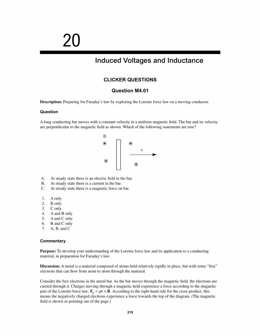
A long conducting bar moves with a constant velocity in a uniform magnetic fi eld. The bar and its velocity are perpendicular to the magnetic fi eld as shown. Which of the following statements are true?
B
v
A. At steady state there is an electric fi eld in the bar. B. At steady state there is a current in the bar. C. At steady state there is a magnetic force on bar.
1. A only 2. B only 3. C only 4. A and B only 5. A and C only 6. B and C only 7. A, B, and C
Commentary
Purpose: To develop your understanding of the Lorentz force law and its application to a conducting material, in preparation for Faraday’s law.
Discussion: A metal is a material composed of atoms held relatively rigidly in place, but with some “free” electrons that can fl ow from atom to atom through the material.
Consider the free electrons in the metal bar. As the bar moves through the magnetic fi eld, the electrons are carried through it. Charges moving through a magnetic fi eld experience a force according to the magnetic part of the Lorentz force law, F v BB = ×q . According to the right-hand rule for the cross product, this means the negatively charged electrons experience a force towards the top of the diagram. (The magnetic fi eld is shown as pointing out of the page.)
219
56157_20_ch20_p219-251.indd 21956157_20_ch20_p219-251.indd 219 3/19/08 1:49:54 AM3/19/08 1:49:54 AM
220 Chapter 20
This force will push the electrons towards the top end of the bar. Since they cannot escape the isolated bar, they will “pile up” there, developing a negative static charge at that end of the bar. The other end of the bar will develop a positive static charge, since electrons are moving away from it and leaving positively charged metal ions behind. (The ions experience a force toward the bottom of the diagram, but because they are not free to move, they remain in place.)
As these static charges accumulate, they create an electric fi eld within the bar, pointing from the positively charged bottom to the negatively charged top. According to the electric part of the Lorentz force law, F
E � qE, this causes a downward force on the electrons. As the electrons move and the static charge builds
up, the strength of this electric force will grow until its magnitude is equal to the magnetic force on the electrons. Since it acts in the opposite direction of the magnetic force, this will result in a zero net force on the electrons, and they will cease to move. The static charge arrangement will not increase any more, and the electrons in the bar have reached “steady state”: the electric force balances the magnetic force, and electrons no longer move.
Thus, statement A is true, and statement B is false.
Statement C is about the net magnetic force on the bar, not just on the electrons within it. Since the bar has no net charge, it contains as many positive protons as negative electrons. Once steady state is reached, all charges move with the same velocity, and the upward magnetic force on all the electrons is exactly bal-anced by the downward magnetic force on all the protons. So, there is no net magnetic force.
(Before steady state is reached, the situation is much more complicated. While current fl ows, the F L B= ×I form of the magnetic force law tells us that the bar will experience a magnetic force.)
Key Points:
• Conducting materials are composed of positive and negative charges. For metals, some of the negative charges can move while the rest of the negative charges and all of the positive charges are fi xed in place.
• Analyzing current fl ow in “wires” from a microscopic perspective, by considering the Lorentz force on the charged particles, can be helpful.
• When charges move in an isolated conductor, they eventually build up a static charge distribution that prevents any further charge motion. (Motion around a circuit is different.)
For Instructors Only
This question can get exceedingly tacky, which makes it valuable for exploring and developing students’ understanding. In particular, taking a microscopic perspective to explain how the bar can experience a nonzero magnetic force before steady state but not in steady state is very diffi cult.
This question can be used to relate Faraday’s law to the Lorentz force law. Another way to approach the situation is to make the bar part of an imaginary closed path, and apply Faraday’s law. That can help explain why charge initially fl ows. Students must understand, however, that Faraday’s law specifi es the emf around any closed path — not just a conducting loop.
Question M4.02
Description: Understanding Faraday’s law by identifying situations for which an emf is induced.
Question
For which of the following is an emf induced?
56157_20_ch20_p219-251.indd 22056157_20_ch20_p219-251.indd 220 3/19/08 1:49:55 AM3/19/08 1:49:55 AM
Induced Voltages and Inductance 221
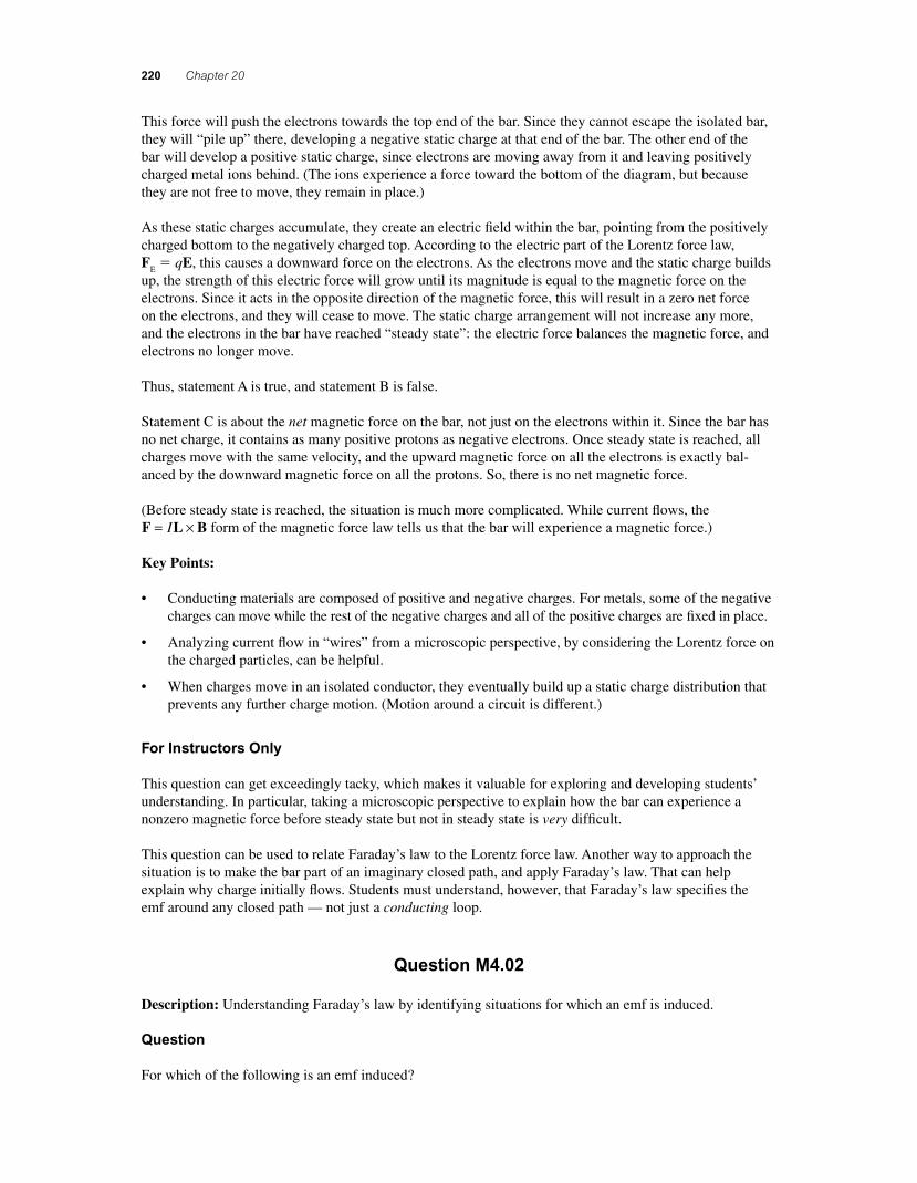
A. A conducting rod is pulled on conducting rails that are placed in a uniform magnetic fi eld directed into the page.
B. A conducting loop moves through a uniform magnetic fi eld directed into the page. C. A conducting loop rotates in a uniform magnetic fi eld directed into the page. D. A conducting loop moves in a magnetic fi eld produced by an infi nite current-carrying wire.
1. A only 2. A and B only 3. A and C only 4. A and D only 5. B and C only 6. A, B, and C 7. A, C, and D 8. All of them 9. None of the above
Commentary
Purpose: To develop an intuitive understanding of when an emf is or is not induced, according to Faraday’s law.
Discussion: According to Faraday’s law, the magnitude of the emf induced around a closed loop is equal to the rate of change of the magnetic fl ux through the loop. For a uniform magnetic fi eld B and a loop with area S all in one plane, the fl ux is Φ = ⋅B S where the direction of the vector S is normal to the loop.
There are three ways that the fl ux B · S can change: the magnetic fi eld strength can change, the area of the loop can change, or the angle between them can change.
In situation A, a uniform magnetic fi eld into the page (not shown in the fi gure, but described in statement A) causes a fl ux through the loop formed by the resistor, portions of the two rails, and the moving rod. As the rod moves, the area of this loop grows, so an emf is induced.
In situation B, the net fl ux through the loop is not changing: neither the fi eld strength, nor the loop size, nor their relative orientation changes. The fl ux gained by the leading edge of the loop is lost by the trailing edge. So, no emf is induced.
56157_20_ch20_p219-251.indd 22156157_20_ch20_p219-251.indd 221 3/19/08 1:49:55 AM3/19/08 1:49:55 AM
222 Chapter 20
In situation C, the angle between the fi eld and the loop does change as the loop rotates, so an emf is gener-ated. (This is the mechanism underlying an electric generator in, say, a hydroelectric power plant.)
In situation D, the current I in the infi nite wire creates a magnetic fi eld that circulates around it, so there is a nonzero fl ux through the moving loop. However, as the loop moves vertically the magnetic fi eld it encounters does not change. Neither its size nor its orientation relative to the fi eld change either, so no emf is induced. (If the loop were to move horizontally, away from the wire, the fl ux would decrease and an emf would be induced.)
Thus, answer 3 is best.
Key Points:
• An emf is induced around a closed path whenever the net magnetic fl ux through that path changes with time.
• There are three ways the fl ux through a path can change: the magnetic fi eld strength can change, the area enclosed by the path can change, or the angle between them can change.
• Not all moving loops in magnetic fi elds experience an induced emf.
For Instructors Only
This problem is well suited to helping students develop an understanding of Faraday’s law when they are fi rst exposed to it.
To work well with Faraday’s law, students need a fi rm, intuitive grasp of “magnetic fl ux” and the ability to visualize it.
Discussing each case from a microscopic perspective, using the Lorentz force law, might help students understand why current fl ows in the loops experiencing a change in magnetic fl ux.
Question N4.01a
Description: Introducing inductors as circuit elements.
Question
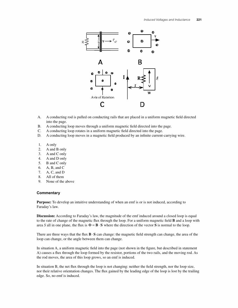
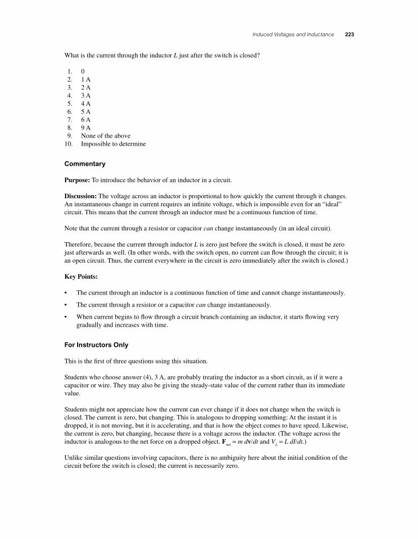
Consider the circuit below. Switch S is closed at t = 0.
56157_20_ch20_p219-251.indd 22256157_20_ch20_p219-251.indd 222 3/19/08 1:49:56 AM3/19/08 1:49:56 AM
Induced Voltages and Inductance 223
What is the current through the inductor L just after the switch is closed?
1. 0 2. 1 A 3. 2 A 4. 3 A 5. 4 A 6. 5 A 7. 6 A 8. 9 A 9. None of the above 10. Impossible to determine
Commentary
Purpose: To introduce the behavior of an inductor in a circuit.
Discussion: The voltage across an inductor is proportional to how quickly the current through it changes. An instantaneous change in current requires an infi nite voltage, which is impossible even for an “ideal” circuit. This means that the current through an inductor must be a continuous function of time.
Note that the current through a resistor or capacitor can change instantaneously (in an ideal circuit).
Therefore, because the current through inductor L is zero just before the switch is closed, it must be zero just afterwards as well. (In other words, with the switch open, no current can fl ow through the circuit; it is an open circuit. Thus, the current everywhere in the circuit is zero immediately after the switch is closed.)
Key Points:
• The current through an inductor is a continuous function of time and cannot change instantaneously.
• The current through a resistor or a capacitor can change instantaneously.
• When current begins to fl ow through a circuit branch containing an inductor, it starts fl owing very gradually and increases with time.
For Instructors Only
This is the fi rst of three questions using this situation.
Students who choose answer (4), 3 A, are probably treating the inductor as a short circuit, as if it were a capacitor or wire. They may also be giving the steady-state value of the current rather than its immediate value.
Students might not appreciate how the current can ever change if it does not change when the switch is closed. The current is zero, but changing. This is analogous to dropping something: At the instant it is dropped, it is not moving, but it is accelerating, and that is how the object comes to have speed. Likewise, the current is zero, but changing, because there is a voltage across the inductor. (The voltage across the inductor is analogous to the net force on a dropped object. F
net = m dv/dt and V
L = L dI/dt.)
Unlike similar questions involving capacitors, there is no ambiguity here about the initial condition of the circuit before the switch is closed; the current is necessarily zero.
56157_20_ch20_p219-251.indd 22356157_20_ch20_p219-251.indd 223 3/19/08 1:49:57 AM3/19/08 1:49:57 AM
224 Chapter 20
Question N4.01b
Description: Introducing inductors as circuit elements.
Question
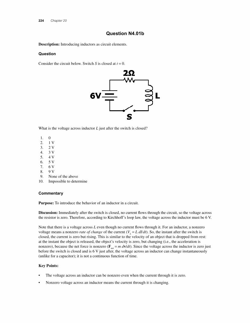
Consider the circuit below. Switch S is closed at t = 0.
What is the voltage across inductor L just after the switch is closed?
1. 0 2. 1 V 3. 2 V 4. 3 V 5. 4 V 6. 5 V 7. 6 V 8. 9 V 9. None of the above 10. Impossible to determine
Commentary
Purpose: To introduce the behavior of an inductor in a circuit.
Discussion: Immediately after the switch is closed, no current fl ows through the circuit, so the voltage across the resistor is zero. Therefore, according to Kirchhoff’s loop law, the voltage across the inductor must be 6 V.
Note that there is a voltage across L even though no current fl ows through it. For an inductor, a nonzero voltage means a nonzero rate of change of the current (V
L = L dI/dt). So, the instant after the switch is
closed, the current is zero but rising. This is similar to the velocity of an object that is dropped from rest: at the instant the object is released, the object’s velocity is zero, but changing (i.e., the acceleration is nonzero), because the net force is nonzero (F
net = m dv/dt). Since the voltage across the inductor is zero just
before the switch is closed and is 6 V just after, the voltage across an inductor can change instantaneously (unlike for a capacitor); it is not a continuous function of time.
Key Points:
• The voltage across an inductor can be nonzero even when the current through it is zero.
• Nonzero voltage across an inductor means the current through it is changing.
56157_20_ch20_p219-251.indd 22456157_20_ch20_p219-251.indd 224 3/19/08 1:49:57 AM3/19/08 1:49:57 AM
Induced Voltages and Inductance 225
• For an inductor, current is a continuous function of time, but voltage is not.
• We can say that an inductor with no current through it behaves like an “open circuit” for an instant.
For Instructors Only
This is the second of three questions using this situation.
Students who select answer (1) may be treating the inductor like a capacitor, for which the voltage cannot change instantaneously. Or, they may know that the current through the inductor is zero and then apply Ohm’s law as if the inductor were a resistor to say that the voltage must also be zero.
Additional Questions: [instructor notes]
1. What is the voltage across the inductor just before the switch is closed? [The voltage across the inductor is zero, because the current is not changing. Kirchhoff’s loop law is satisfi ed, because the voltage drop across the switch is 6 V.]
2. Sketch current vs. time through the inductor. 3. For L = 25 mH, what is the rate at which the current through the inductor is changing just after the
switch is closed? That is, what is the slope of the current vs. time graph?
Question N4.01c
Description: Introducing inductors as circuit elements.
Question
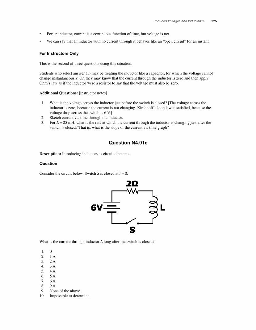
Consider the circuit below. Switch S is closed at t = 0.
What is the current through inductor L long after the switch is closed?
1. 0 2. 1 A 3. 2 A 4. 3 A 5. 4 A 6. 5 A 7. 6 A 8. 9 A 9. None of the above 10. Impossible to determine
56157_20_ch20_p219-251.indd 22556157_20_ch20_p219-251.indd 225 3/19/08 1:49:57 AM3/19/08 1:49:57 AM
226 Chapter 20
Commentary
Purpose: To introduce the behavior of an inductor in a circuit.
Discussion: The voltage across an inductor is proportional to the rate of change of the current through it. After a long time, the current through the inductor has reached a constant, steady-state value, so the voltage across it must be zero. In other words, an inductor in steady state behaves like a “short circuit.”
Since the voltage drop across the inductor is zero, the voltage drop across the resistor must be 6 V accord-ing to Kirchhoff’s loop law, so 3 A fl ows everywhere in the circuit.
Note that for resistors, a current fl ow indicates a nonzero voltage drop; for inductors, a change in current fl ow indicates a nonzero voltage drop.
Key Points:
• In steady state (i.e., for constant current), the voltage across an inductor is zero.
• An inductor may have current through it without any voltage drop across it.
For Instructors Only
This is the last of 3 questions using this situation.
It might be hard for students to understand how the voltage drop across something with current can be zero.
Students who say the current is zero (answer 1) may be treating the inductor as a capacitor, in which the current goes to zero asymptotically.
Asking students to sketch the current through and voltage across the inductor vs. time, and relating the two graphs, may be helpful.
It can also help to redraw the circuit with the inductor replaced by a wire.
Question N4.02a
Description: Extending understanding of inductor behavior in DC circuits.
Question
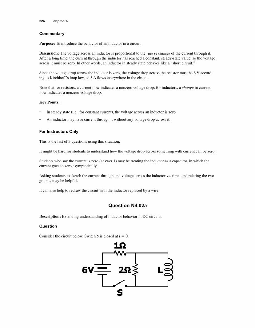
Consider the circuit below. Switch S is closed at t � 0.
56157_20_ch20_p219-251.indd 22656157_20_ch20_p219-251.indd 226 3/19/08 1:49:58 AM3/19/08 1:49:58 AM
Induced Voltages and Inductance 227
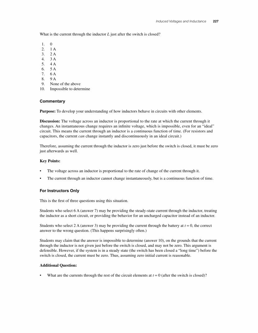
What is the current through the inductor L just after the switch is closed?
1. 0 2. 1 A 3. 2 A 4. 3 A 5. 4 A 6. 5 A 7. 6 A 8. 9 A 9. None of the above 10. Impossible to determine
Commentary
Purpose: To develop your understanding of how inductors behave in circuits with other elements.
Discussion: The voltage across an inductor is proportional to the rate at which the current through it changes. An instantaneous change requires an infi nite voltage, which is impossible, even for an “ideal” circuit. This means the current through an inductor is a continuous function of time. (For resistors and capacitors, the current can change instantly and discontinuously in an ideal circuit.)
Therefore, assuming the current through the inductor is zero just before the switch is closed, it must be zero just afterwards as well.
Key Points:
• The voltage across an inductor is proportional to the rate of change of the current through it.
• The current through an inductor cannot change instantaneously, but is a continuous function of time.
For Instructors Only
This is the fi rst of three questions using this situation.
Students who select 6 A (answer 7) may be providing the steady-state current through the inductor, treating the inductor as a short circuit, or providing the behavior for an uncharged capacitor instead of an inductor.
Students who select 2 A (answer 3) may be providing the current through the battery at t = 0, the correct answer to the wrong question. (This happens surprisingly often.)
Students may claim that the answer is impossible to determine (answer 10), on the grounds that the current through the inductor is not given just before the switch is closed, and may not be zero. This argument is defensible. However, if the system is in a steady state (the switch has been closed a “long time”) before the switch is closed, the current must be zero. Thus, assuming zero initial current is reasonable.
Additional Question:
• What are the currents through the rest of the circuit elements at t = 0 (after the switch is closed)?
56157_20_ch20_p219-251.indd 22756157_20_ch20_p219-251.indd 227 3/19/08 1:49:58 AM3/19/08 1:49:58 AM
228 Chapter 20
Question N4.02b
Description: Extending understanding of inductor behavior in DC circuits.
Question
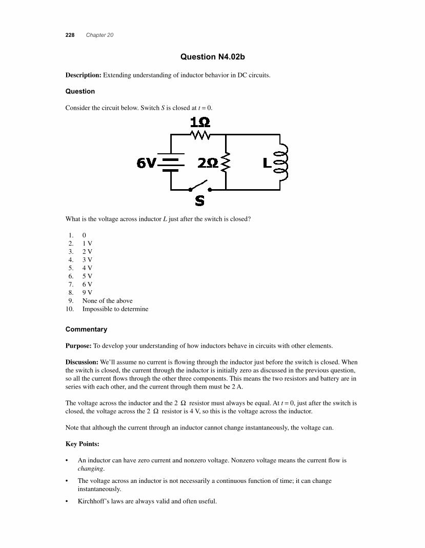
Consider the circuit below. Switch S is closed at t = 0.
What is the voltage across inductor L just after the switch is closed?
1. 0 2. 1 V 3. 2 V 4. 3 V 5. 4 V 6. 5 V 7. 6 V 8. 9 V 9. None of the above 10. Impossible to determine
Commentary
Purpose: To develop your understanding of how inductors behave in circuits with other elements.
Discussion: We’ll assume no current is fl owing through the inductor just before the switch is closed. When the switch is closed, the current through the inductor is initially zero as discussed in the previous question, so all the current fl ows through the other three components. This means the two resistors and battery are in series with each other, and the current through them must be 2 A.
The voltage across the inductor and the 2 Ω resistor must always be equal. At t = 0, just after the switch is closed, the voltage across the 2 Ω resistor is 4 V, so this is the voltage across the inductor.
Note that although the current through an inductor cannot change instantaneously, the voltage can.
Key Points:
• An inductor can have zero current and nonzero voltage. Nonzero voltage means the current fl ow is changing.
• The voltage across an inductor is not necessarily a continuous function of time; it can change instantaneously.
• Kirchhoff’s laws are always valid and often useful.
56157_20_ch20_p219-251.indd 22856157_20_ch20_p219-251.indd 228 3/19/08 1:49:58 AM3/19/08 1:49:58 AM
Induced Voltages and Inductance 229
For Instructors Only
This is the second of three questions using this situation.
Students who answer zero might be treating the inductor as a capacitor, for which voltage and current are proportional. They may also be treating it as a capacitor, for which voltage cannot change instantaneously.
Students who answer 6 V may be erroneously generalizing from simpler circuits in which the voltage across an inductor jumps to the battery’s voltage. This would be correct here if the 2 Ω resistor were removed, or if the 1 Ω resistor were replaced by wire.
It might be hard for students to realize that they need to focus on the 2 Ω resistor in order to fi nd the volt-age across the inductor. But this is a good opportunity to discuss problem-solving skills, since it is often fruitful to transform a hard question into an easier one. In this case, if you had asked students to tell you the voltage across the 2 Ω resistor just after the switch is closed, many more would be able to do so. (Not all, since they must also recognize that there is no current through L.)
This question is also a good opportunity to discuss the continued usefulness of Kirchhoff’s laws.
As with the previous question, “impossible to determine” because the initial condition is unspecifi ed is defensible but not laudable, since any current circulating through the inductor and 2 Ω resistor will damp out if the switch is open for signifi cant time.
Additional Questions:
• What is the voltage across the inductor just before the switch is closed?
• Sketch the current through the inductor vs. time.
• For L = 25 mH, what is the rate at which the current through the inductor is changing just after the switch is closed? (What is the slope of current vs. time?)
Question N4.02c
Description: Extending understanding of inductor behavior in DC circuits.
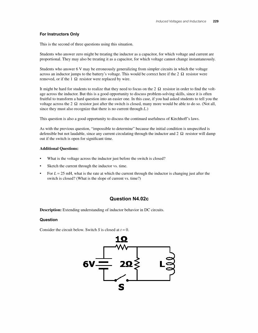
Question
Consider the circuit below. Switch S is closed at t = 0.
56157_20_ch20_p219-251.indd 22956157_20_ch20_p219-251.indd 229 3/19/08 1:49:59 AM3/19/08 1:49:59 AM
230 Chapter 20
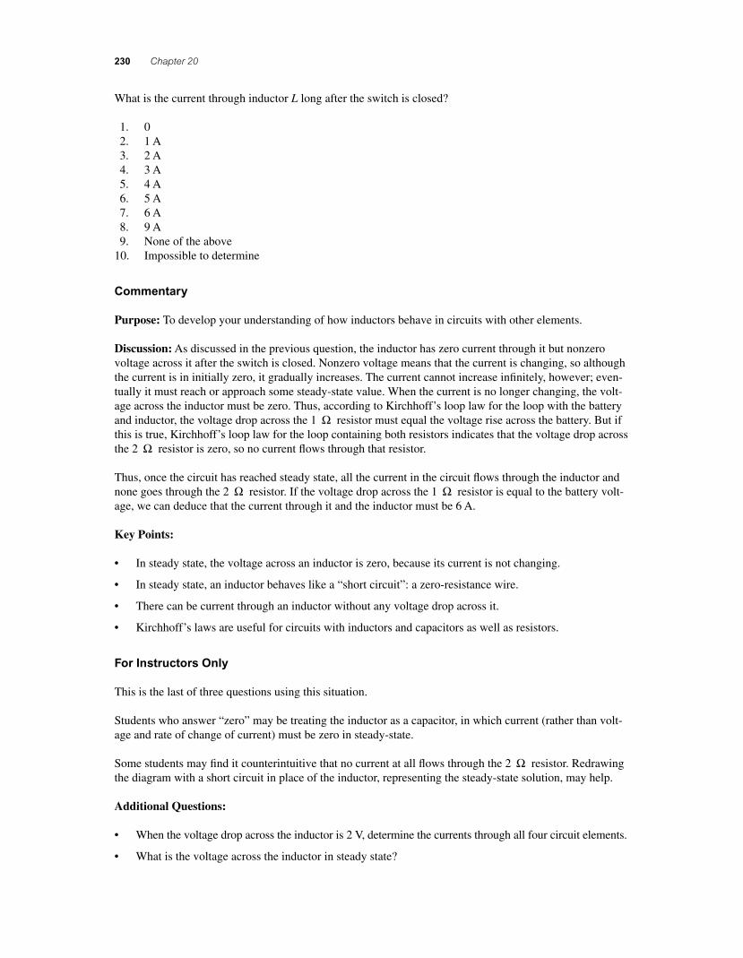
What is the current through inductor L long after the switch is closed?
1. 0 2. 1 A 3. 2 A 4. 3 A 5. 4 A 6. 5 A 7. 6 A 8. 9 A 9. None of the above 10. Impossible to determine
Commentary
Purpose: To develop your understanding of how inductors behave in circuits with other elements.
Discussion: As discussed in the previous question, the inductor has zero current through it but nonzero voltage across it after the switch is closed. Nonzero voltage means that the current is changing, so although the current is in initially zero, it gradually increases. The current cannot increase infi nitely, however; even-tually it must reach or approach some steady-state value. When the current is no longer changing, the volt-age across the inductor must be zero. Thus, according to Kirchhoff’s loop law for the loop with the battery and inductor, the voltage drop across the 1 Ω resistor must equal the voltage rise across the battery. But if this is true, Kirchhoff’s loop law for the loop containing both resistors indicates that the voltage drop across the 2 Ω resistor is zero, so no current fl ows through that resistor.
Thus, once the circuit has reached steady state, all the current in the circuit fl ows through the inductor and none goes through the 2 Ω resistor. If the voltage drop across the 1 Ω resistor is equal to the battery volt-age, we can deduce that the current through it and the inductor must be 6 A.
Key Points:
• In steady state, the voltage across an inductor is zero, because its current is not changing.
• In steady state, an inductor behaves like a “short circuit”: a zero-resistance wire.
• There can be current through an inductor without any voltage drop across it.
• Kirchhoff’s laws are useful for circuits with inductors and capacitors as well as resistors.
For Instructors Only
This is the last of three questions using this situation.
Students who answer “zero” may be treating the inductor as a capacitor, in which current (rather than volt-age and rate of change of current) must be zero in steady-state.
Some students may fi nd it counterintuitive that no current at all fl ows through the 2 Ω resistor. Redrawing the diagram with a short circuit in place of the inductor, representing the steady-state solution, may help.
Additional Questions:
• When the voltage drop across the inductor is 2 V, determine the currents through all four circuit elements.
• What is the voltage across the inductor in steady state?
56157_20_ch20_p219-251.indd 23056157_20_ch20_p219-251.indd 230 3/19/08 1:49:59 AM3/19/08 1:49:59 AM
Induced Voltages and Inductance 231
• After steady state is reached, the switch is opened again. Just after the switch is opened, determine the current through the inductor, the current through the 2 Ω resistor, the current through the 1 Ω resistor, and the voltage across the inductor.
Question N4.03
Description: Linking energy conservation ideas to inductor circuits.
Question
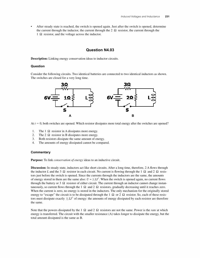
Consider the following circuits. Two identical batteries are connected to two identical inductors as shown. The switches are closed for a very long time.
A B
At t � 0, both switches are opened. Which resistor dissipates more total energy after the switches are opened?
1. The 1 Ω resistor in A dissipates more energy. 2. The 2 Ω resistor in B dissipates more energy. 3. Both resistors dissipate the same amount of energy. 4. The amounts of energy dissipated cannot be compared.
Commentary
Purpose: To link conservation of energy ideas to an inductive circuit.
Discussion: In steady state, inductors act like short circuits. After a long time, therefore, 2 A fl ows through the inductor L and the 3 Ω resistor in each circuit. No current is fl owing through the 1 Ω and 2 Ω resis-tors just before the switch is opened. Since the currents through the inductors are the same, the amounts of energy stored in them are the same also: U LI= 1
22. When the switch is opened again, no current fl ows
through the battery or 3 Ω resistor of either circuit. The current through an inductor cannot change instan-taneously, so current fl ows through the 1 Ω and 2 Ω resistors, gradually decreasing until it reaches zero. When the current is zero, no energy is stored in the inductors. The only mechanism for the originally stored energy to “escape” the circuit is to be dissipated through the 1 Ω or 2 Ω resistor. So, each of these resis-tors must dissipate exactly 1
22LI of energy: the amounts of energy dissipated by each resistor are therefore
the same.
Note that the powers dissipated by the 1 Ω and 2 Ω resistors are not the same. Power is the rate at which energy is transferred. The circuit with the smaller resistance (A) takes longer to dissipate the energy, but the total amount dissipated is the same as B.
56157_20_ch20_p219-251.indd 23156157_20_ch20_p219-251.indd 231 3/19/08 1:50:00 AM3/19/08 1:50:00 AM
232 Chapter 20
Key Points:
• The energy U stored in an inductor L with current I fl owing through it is U LI= 12
2.
• An inductor acts like a short circuit in a steady-state situation.
• The current through an inductor cannot change instantaneously. (The current through a resistor, however, can.)
For Instructors Only
Students might not realize that the current in each inductor is the same just before the switches are opened. They might think that the current at steady state depends on the value of the resistance in parallel with L (1 Ω or 2 Ω).
Students might think that they need to know L to determine the current in steady state.
Students choosing answer (1) may be thinking that more energy is dissipated in circuit A because the cur-rent takes more time to damp out (having a longer L/R time constant).
Students choosing answer (2) may be thinking that more energy is dissipated in circuit B either because the initial voltage across the 2 Ω resistor is larger or because its resistance (and therefore power dissipation) is larger.
Students choosing answer (4) may think they need a value for L so they can perform actual calculations.
QUICK QUIZZES
1. b, c, a. At each instant, the magnitude of the induced emf is proportional to the rate of change of the magnetic fi eld (hence, proportional to the slope of the curve shown on the graph).
2. (a). All charged particles within the metal bar move straight downward with the bar. According to right-hand rule #1, positive changes moving downward through a magnetic fi eld that is directed northward will experience magnetic forces toward the east. This means that the free electrons (negative charges) within the metal will experience westward forces and will drift toward the west end of the bar, leaving the east end with a net positive charge.
3. (b). According to Equation (20.3), because B and v are constant, the emf depends only on the length of the wire moving in the magnetic fi eld. Thus, you want the long dimension moving through the magnetic fi eld lines so that it is perpendicular to the velocity vector. In this case, the short dimension is parallel to the velocity vector. From a more conceptual point of view, you want the rate of change of area in the magnetic fi eld to be the largest, which you do by thrusting the long dimension into the fi eld.
4. (c). In order to oppose the approach of the north pole, the magnetic fi eld generated by the induced current must be directed upward. An induced current directed counterclockwise around the loop will produce a fi eld with this orientation along the axis of the loop.
5. (b). As the counterclockwise current in the left-hand loop increases, it produces an increasing downward fl ux through the area enclosed by the right-hand loop. This changing fl ux will induce a counterclockwise current in the right-hand loop in order to oppose the increasing fl ux from the left-hand loop.
56157_20_ch20_p219-251.indd 23256157_20_ch20_p219-251.indd 232 3/19/08 1:50:01 AM3/19/08 1:50:01 AM
Induced Voltages and Inductance 233
6. (b). When the iron rod is inserted into the solenoid, the inductance of the coil increases. As a result, more potential difference appears across the coil than before. Consequently, less potential difference appears across the bulb, and its brightness decreases.
ANSWERS TO MULTIPLE CHOICE QUESTIONS
1. Since the magnetic fi eld is directed at a 30.0° angle with respect to the plane of the loop, the angle between the fi eld and the normal to the plane of the loop is θ = 60 0. °. Thus, the fl ux through the rectangular area is
ΦB BA= cos . . . cos .θ = ( ) ( )( )⎡⎣ ⎤⎦3 0 2 0 1 0 60 0 T m m ° == ⋅ =3 0 3 0. . T m Wb2
and (c) is the correct choice.
2. Choose the positive z-direction to be the reference direction ( )θ = 0° for the normal to the plane of the coil. Then, the change in fl ux through the coil is
ΔΦB f f i iB B A= −( ) = ( ) − ( )cos cos . cos .θ θ 3 0 0 1 0 T T° ccos . .180 0 5 1 0
2°⎡⎣ ⎤⎦( ) = m Wb
and the magnitude of the induced emf is
ε = = ( )⎛
⎝⎜⎞⎠⎟ =N
tBΔΦ
Δ10
1 05 0
..
Wb
2.0 s V
The correct answer is choice (b).
3. The motional emf induced in a conductor of length l moving at speed v through a magnetic fi eld of magnitude B is ΔV B B= = ( )⊥l lv vsinθ , where B B⊥ = sinθ is the component of the fi eld perpendicular to the velocity of the conductor. In the described situation,
ΔV B B= = ( ) = ×( )⎡⎣ ⎤⎦⊥
−l lv vsin . sin .θ 60 0 10 60 06 T ° 112 60 0 3 7 10 372 m m s V mV( )( ) = × =−. .
and the correct choice is (c).
4. The angular velocity of the rotating coil is ω π= =10 0 20. rev s rad s and the maximum emf induced in the coil is
ε ω πmax . .= = ( )( )( )NBA 100 0 050 0 0 100 20 T m rad s2 (( ) = 31 4. V
showing the correct choice to be (a).
5. The magnitude of the voltage drop across the inductor is
εL L
I
t= = ( )( ) =Δ
Δ5 00 2 00 10 0. . . H A s V
and (d) is the correct choice.
6. From iR
e I et t= −( ) = −( )− −ε τ τ1 1max , the time when i I= max 2 is given by e t− =τ 1 2 or
et τ = 2, yielding t = τ ln 2. Since the time constant of the circuit is τ = = =L
R
5 02 0
..
H
2.5 s
Ω, the
desired time is t = ( ) =2 0 2 1 4. ln . s s and the answer closest to this result is choice (d).
56157_20_ch20_p219-251.indd 23356157_20_ch20_p219-251.indd 233 3/19/08 1:50:01 AM3/19/08 1:50:01 AM
234 Chapter 20
7. The energy stored in an inductor of inductance L and carrying current I is PE LIL = 12
2 . Thus, if the current is doubled while the inductance is constant, the stored energy increases by a factor of 4 and the correct choice is (d).
8. An emf is induced in the coil by any action which causes a change in the fl ux through the coil. The actions described in choices (a), (b), (d), and (e) all change the fl ux through the coil and induce an emf. However, moving the coil through the constant fi eld without changing its orientation with respect to the fi eld will not cause a change of fl ux. Thus, choice (c) is the correct answer.
9. With the current in long wire fl owing in the direction shown in Figure MCQ20.9, the magnetic fl ux through the rectangular loop is directed into the page. If this current is decreasing in time, the change in the fl ux is directed opposite to the fl ux itself (or out of the page). The induced current will then fl ow clockwise around the loop, producing a fl ux directed into the page through the loop and opposing the change in fl ux due to the decreasing current in the long wire. The correct choice is for this question is (b).
10. A current fl owing counterclockwise in the outer loop of Figure MCQ20.10 produces a magnetic fl ux through the inner loop that is directed out of the page. If this current is increasing in time, the change in the fl ux is in the same direction as the fl ux itself (or out of the page). The induced cur-rent in the inner loop will then fl ow clockwise around the loop, producing a fl ux through the loop directed into the page, opposing the change in fl ux due to the increasing current in the outer loop. The correct answer is choice (b).
11. As the bar magnet approaches the loop from above, with its south end downward as shown in Figure MCQ20.11, magnetic fl ux through the area enclosed by the loop is directed upward and increasing in magnitude. To oppose this increasing upward fl ux, the induced current in the loop will fl ow clockwise, as seen from above, producing a fl ux directed downward through the area enclosed by the loop. After the bar magnet has passed through the plane of the loop, and is departing with its north end upward, a decreasing fl ux is directed upward through the loop. To oppose this decreasing upward fl ux, the induced current in the loop fl ows counterclockwise as seen from above, producing fl ux directed upward through the area enclosed by the loop. From this analysis, we see that (a) is the only true statement among the listed choices.
12. With the magnetic fi eld perpendicular to the plane of the page in Figure MCQ20.12, the fl ux through the closed loop to the left of the bar is given by ΦB BA= , where B is the magnitude of the fi eld and A is the area enclosed by the loop. Any action which produces a change in this product, BA, will induce a current in the loop and cause the bulb to light. Such actions include increasing or decreasing the magnitude of the fi eld (B), and moving the bar to the right or left and changing the enclosed area A. Thus, the bulb will light during all of the actions in choices (a), (b), (c), and (d).
ANSWERS TO CONCEPTUAL QUESTIONS
2. Consider the copper tube to be a large set of rings stacked one on top of the other. As the magnet falls toward or falls away from each ring, a current is induced in the ring. Thus, there is a current in the copper tube around its circumference.
4. The fl ux is calculated as ΦB BA B A= = ⊥cosθ . The fl ux is therefore maximum when the magnetic fi eld vector is perpendicular to the plane of the loop. We may also deduce that the fl ux is zero when there is no component of the magnetic fi eld that is perpendicular to the loop.
6. No. Once the bar is in motion and the charges are separated, no external force is necessary to main-tain the motion. An applied force in the x-direction will cause the bar to accelerate in that direction.
56157_20_ch20_p219-251.indd 23456157_20_ch20_p219-251.indd 234 3/19/08 1:50:02 AM3/19/08 1:50:02 AM
Induced Voltages and Inductance 235
8. As water falls, it gains velocity and kinetic energy. It then pushes against the blades of a turbine, transferring this energy to the rotor or coil of a large alternating current generator. The rotor moves in a strong external magnetic fi eld and a voltage is induced in the coil. This induced emf is the voltage source for the current in our electric power lines.
10. Let us assume the north pole of the magnet faces the ring. As the bar magnet falls toward the conducting ring, a magnetic fi eld is induced in the ring pointing upward. This upward directed fi eld will oppose the motion of the magnet preventing it from moving as a freely-falling body. Try it for yourself to show that an upward force also acts on the falling magnet if the south end faces the ring.
12. A constant induced emf requires a magnetic fi eld that is changing at a constant rate in one direction — for example, always increasing or always decreasing. It is impossible for a magnetic fi eld to increase forever, both in terms of energy considerations and technological concerns. In the case of a decreasing fi eld, once it reaches zero and then reverses direction, we again face the problem with the fi eld increasing without bounds in the opposite direction.
14. As the magnet moves at high speed past the fi xed coil, the magnetic fl ux through the coil changes very rapidly, increasing as the magnet approaches the coil and decreasing as the magnet moves away. The rapid change in fl ux through the coil induces a large emf, large enough to cause a spark across the gap in the spark plug.
PROBLEM SOLUTIONS
20.1 The angle between the direction of the constant fi eld and the normal to the plane of the loop is θ = 0°, so
ΦB BA= = ( ) ×( ) ×( )⎡⎣
− −cos . .θ 0 50 8 0 10 12 102 2 T m m ⎤⎤⎦ = × ⋅ =−cos . .0 4 8 10 4 83° T m mWb2
20.2 The magnetic fl ux through the loop is given by ΦB BA= cosθ, where B is the magnitude of the magnetic fi eld, A is the area enclosed by the loop, and θ is the angle the magnetic fi eld makes with the normal to the plane of the loop. Thus,
ΦB BA= = ×( ) ⎛⎝
−−
cos . .θ 5 00 10 20 05 T cm10 m
1 cm2
2
⎜⎜⎞⎠⎟
⎡
⎣⎢⎢
⎤
⎦⎥⎥
= × ⋅( )−2
71 00 10cos . cosθ θ T m2
(a) When Bur
is perpendicular to the plane of the loop, θ = 0° and ΦB = × ⋅−1 00 10 7. T m2
(b) If θ = = × ⋅( )−30 0 1 00 10 30 07. . cos .°, then T m2ΦB °° = × ⋅−8 66 10 8. T m2
(c) If θ = = × ⋅( )−90 0 1 00 10 90 07. . cos .°, then T m2ΦB °° = 0
20.3 ΦB BA B r= =cos ( )cosθ π θ2
where θ is the angle between the direction of the fi eld and the normal to the plane of the loop.
(a) If the fi eld is perpendicular to the plane of the loop, θ = 0°, and
Br
B= ( ) = × ⋅( )
−Φπ θ π2
3
2
8 00 10
0 12 0cos
.
. cos
T m
m
2
°== 0 177. T
(b) If the fi eld is directed parallel to the plane of the loop, θ = °90 , and
ΦB BA BA= = =cos cosθ 90 0°
56157_20_ch20_p219-251.indd 23556157_20_ch20_p219-251.indd 235 3/19/08 1:50:03 AM3/19/08 1:50:03 AM
236 Chapter 20
20.4 The magnetic fi eld lines are tangent to the surface of the cylinder, so that no magnetic fi eld lines penetrate the cylindrical surface. The total fl ux through the cylinder is zero .
20.5 (a) Every fi eld line that comes up through the area A on one side of the wire goes back down through area A on the other side of the wire. Thus, the net fl ux through the coil is zero .
(b) The magnetic fi eld is parallel to the plane of the coil, so θ = 90 0. °. Therefore, ΦB BA BA= = =cos cos .θ 90 0 0°
20.6 (a) The magnitude of the fi eld inside the solenoid is
B nIN
I= = ⎛⎝⎜
⎞⎠⎟ = × ⋅( )−μ μ π0 0
74 10400
0 360l T m A
m.⎛⎛⎝⎜
⎞⎠⎟ ( ) = × =−5 00 6 98 10 6 983. . . A T mT
(b) The fi eld inside a solenoid is directed perpendicular to the cross-sectional area, so θ = °0 and the fl ux through a loop of the solenoid is
ΦB BA B= = ( )= ×( ) ×− −
cos cos
. .
θ π θ
π
r 2
36 98 10 3 00 10T 22 2 50 1 97 10m T m2( ) = × ⋅−cos .°
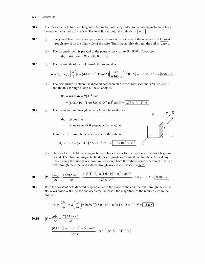
20.7 (a) The magnetic fl ux through an area A may be written as
ΦB B A
B
= ( )=
cosθ
component of perpendicular to A A( ) ⋅
Thus, the fl ux through the shaded side of the cube is
ΦB xB A= ⋅ = ( ) ⋅ ×( ) = × ⋅− −5 0 2 5 10 3 1 102 2 3. . . T m T m2
(b) Unlike electric fi eld lines, magnetic fi eld lines always form closed loops, without beginning or end. Therefore, no magnetic fi eld lines originate or terminate within the cube and any line entering the cube at one point must emerge from the cube at some other point. The net fl ux through the cube, and indeed through any closed surface, is zero .
20.8 ε θ π= = ( ) =
−( ) ×( )−ΔΦΔ
ΔΔ
B
t
B A
t
cos . .1 5 0 1 6 10 3 2 T m⎡⎡
⎣⎤⎦ °
×= × =−
−cos
. .0
120 101 0 10 0 103
4
s V mV
20.9 With the constant fi eld directed perpendicular to the plane of the coil, the fl ux through the coil is ΦB BA BA= =cos 0° . As the enclosed area increases, the magnitude of the induced emf in the coil is
ε = = ⎛
⎝⎜⎞⎠⎟ = ( ) ×( ) =−ΔΦ
ΔΔΔ
B
tB
A
t0 30 5 0 10 3. . T m s2 11 5 10 1 53. .× =− V mV
20.10 ε θ= =
( )ΔΦΔ
ΔΔ
B
t
B A
t
cos
=
( ) ( ) −⎡⎣ ⎤⎦ °= ×
0 15 0 12 0 0
0 203 4 10
2. . cos
..
T m
s
π−− =2 34 V mV
56157_20_ch20_p219-251.indd 23656157_20_ch20_p219-251.indd 236 3/19/08 4:06:35 AM3/19/08 4:06:35 AM
Induced Voltages and Inductance 237
20.11 The magnitude of the induced emf is ε θ= =
( )ΔΦΔ
ΔΔ
B
t
B A
t
cos
If the normal to the plane of the loop is considered to point in the original direction of the mag-netic fi eld, then θ θi f= ° = °0 180 and . Thus, we fi nd
ε π
=( ) − ( ) ( )0 20 180 0 30 0 0 30
1
2. cos . cos .
.
T T m° °
559 4 10 942
s V mV= × =−.
20.12 With the fi eld directed perpendicular to the plane of the coil, the fl ux through the coil is ΦB BA BA= =cos 0° . As the magnitude of the fi eld increases, the magnitude of the induced emf in the coil is
ε π= = ⎛
⎝⎜⎞⎠⎟ = ( ) ( )⎡ΔΦ
ΔΔΔ
B
t
B
tA 0 050 0 0 120
2. . T s m⎣⎣ ⎤⎦ = × =−2 26 10 2 263. . V mV
20.13 The required induced emf is ε = = ( )( ) =IR 0 10 0 80. . A 8.0 VΩ .
From ε θ= = ⎛⎝⎜
⎞⎠⎟
ΔΦΔ
ΔΔ
B
t
B
tNA cos
ΔΔB
t NA= = ( ) ( )( )⎡⎣
εθcos
.
. .
0 80
0 050 0 080
V
75 m m ⎤⎤⎦ °=
cos.
02 7 T s
20.14 The initial magnetic fi eld inside the solenoid is
B nI= = × ⋅( )⎛
⎝⎜⎞⎠⎟
−μ π074 10
100
0 2003 00 T m A
m A
..(( ) = × −1 88 10 3. T
(a) ΦB BA= = ×( ) ×( ) °
=
− −cos . . cosθ 1 88 10 1 00 10 03 2 2 T m
11 88 10 7. × ⋅− T m2
(b) When the current is zero, the fl ux through the loop is ΦB = 0 and the average induced emf has been
ε = =
− × ⋅= ×
−−ΔΦ
ΔB
t
0 1 88 10
3 006 28 10
7
8.
..
T m
s V
2
20.15 (a) The initial fi eld inside the solenoid is
B nIi i= = × ⋅( )⎛
⎝⎜⎞⎠⎟
−μ π074 10
300
0 2002 00 T m A
m.. A T( ) = × −3 77 10 3.
(b) The fi nal fi eld inside the solenoid is
B nIf f= = × ⋅( )⎛
⎝⎜⎞⎠⎟
−μ π074 10
300
0 2005 00 T m A
m.. A T( ) = × −9 42 10 3.
(c) The 4-turn coil encloses an area A r= = ×( ) = ×− −π π2 2 2 41 50 10 7 07 10. . m m2
(d) The change in fl ux through each turn of the 4-turn coil during the 0.900-s period is
ΔΦ ΔB B A= ( ) = × − ×( ) ×− − −9 42 10 3 77 10 7 07 103 3. . . T T 44 63 99 10 m Wb2( ) = × −.
continued on next page
56157_20_ch20_p219-251.indd 23756157_20_ch20_p219-251.indd 237 3/19/08 4:06:15 AM3/19/08 4:06:15 AM
238 Chapter 20
(e) The average induced emf in the 4-turn coil is
ε = ⎛
⎝⎜⎞⎠⎟ = ×⎛
⎝⎜⎞⎠⎟
=−
Nt
B2
6
43 99 10
0 900
ΔΦΔ
.
.
Wb
s11 77 10 5. × − V
Since the current increases at a constant rate during this time interval, the induced emf at any instant during the interval is the same as the average value given above.
(f) The induced emf is small, so the current in the 4-turn coil will also be very small.
This means that the magnetic field generatedd by this current will be negligibly small
iin comparison to the field generated by thee solenoid.
20.16 The magnitude of the average emf is
ε θ=
( )=
( )⎡⎣ ⎤⎦
=( ) ×
N
t
NBA
tBΔΦ
ΔΔΔ
cos
200 1 100 1.1 T 00 0 180
044
4−( ) −( )=
m
.10 s V
2 cos cos° °
Therefore, the average induced current is IR
= = =ε 4
8 84 V
5.0 A
Ω.
20.17 If the magnetic fi eld makes an angle of 28.0° with the plane of the coil, the angle it makes with the normal to the plane of the coil is θ = °62 0. . Thus,
ε θ=
( )= ( )
=×( )−
N
t
NB A
tBΔΦ
ΔΔΔ
cos
.200 5 390.0 10 T6 00 62 0
11
cm 1 m 10 cm
.80 s
2 2 4 2( )( )⎡⎣ ⎤⎦ °=
cos ..002 10 10 25× =− V V. μ
20.18 With the magnetic fi eld perpendicular to the plane of the coil, the fl ux through each turn of the coil is ΦB BA B r= = ( )π 2 . Since the area remains constant, the change in fl ux due to the chang-ing magnitude of the magnetic fi eld is ΔΦ ΔB B r= ( )π 2 .
(a) The induced emf is: ε π π= − ⎛⎝⎜
⎞⎠⎟ = −
−( )−
⎡
⎣⎢
⎤
⎦⎥ = −N
tN
B r
t
NB rΔΦΔ
02
020
0 tt
(b) When looking down on the coil from a location on the positive z-axis, the magnetic fi eld (in the positive z-direction) is directed up toward you and increasing in magnitude. This means the change in the fl ux through the coil is directed upward. In order to oppose this change in fl ux, the current must produce a fl ux directed downward through the area enclosed by the coil. Thus, the current must fl ow clockwise as seen from your viewing location.
(c) Since the turns of the coil are connected in series, the total resistance of the coil is R NReq = . Thus, the magnitude of the induced current is
IR
NB r t
NR
B r
tR= = =
ε π πeq
02
02
56157_20_ch20_p219-251.indd 23856157_20_ch20_p219-251.indd 238 3/19/08 1:50:05 AM3/19/08 1:50:05 AM
Induced Voltages and Inductance 239
20.19 The vertical component of the Earth’s magnetic fi eld is perpendicular to the horizontal velocity of the metallic truck body. Thus, the motional emf induced across the width of the truck is
ε = = ×( ) ( )⎛
⎝⎜⎞⎠⊥
−B lv 35 10 79 816 T in m
39.37 in. ⎟⎟
⎡⎣⎢
⎤⎦⎥( ) = × =−37 2 6 10 2 63 m s V mV. .
20.20 The vertical component of the Earth’s magnetic fi eld is perpendicular to the horizontal velocity of the wire. Thus, the magnitude of the motional emf induced in the wire is
ε = = ×( )( )( ) = ×⊥
−B lv 40 0 10 2 00 15 0 1 206. . . . T m m s 110 1 203− = V mV.
Imagine holding your right hand horizontal with the fi ngers pointing north (the direction of the wire’s velocity), such that when you close your hand the fi ngers curl downward (in the direction of B⊥). Your thumb will then be pointing westward. By right-hand rule 1, the mag-netic force on charges in the wire would tend to move positive charges westward. Thus,
the west end of the wire will be positive reelative to the east end .
20.21 (a) Observe that only the horizontal component, Bh , of Earth’s magnetic fi eld is effective in exerting a vertical force on charged particles in the antenna. For the magnetic force, F q Bm h= v sinθ , on positive charges in the antenna to be directed upward and have maxi-mum magnitude (when q = 90°), the car should move toward the east through the north-ward horizontal component of the magnetic fi eld.
(b) ε = Bhlv, where Bh is the horizontal component of the magnetic fi eld.
ε = ×( )⎡⎣ ⎤⎦( )−50 0 10 65 0 1 20 65 06. cos . . . T m km
h° ⎛⎛
⎝⎜⎞⎠⎟
⎛⎝⎜
⎞⎠⎟
⎡
⎣⎢
⎤
⎦⎥
= × −
0 278
4 58 10 4
.
.
m s
1 km h
V
20.22 (a) Since ε = ⊥B lv, the magnitude of the vertical component of the Earth’s magnetic fi eld at this location is
B Bvertical
V
25 m m s= = = ( ) ×( ) =⊥
εlv
0 45
3 0 106
3
.
... .0 10 6 06× =− T Tμ
(b) Yes. The magnitude and direction of the Earth’s fi eld varies from one location to the other, so the induced voltage in the wire changes. Further, the voltage will change if the tether cord changes its orientation relative to the Earth’s fi eld.
20.23 ε = ⊥B lv, where B⊥ is the component of the magnetic fi eld perpendicular to the velocityrv.
Thus,
ε = ×( )⎡⎣ ⎤⎦( )( )−50 0 10 58 0 60 0 3006. sin . . T m m s° == 0 763. V
20.24 From ε = B lv, the required speed is
v = = =
( )( )( )(
εB
IR
Bl l
0 500 6 00
2 50 1 20
. .
. .
A
T m
Ω)) = 1 00. m s
56157_20_ch20_p219-251.indd 23956157_20_ch20_p219-251.indd 239 3/19/08 4:44:37 AM3/19/08 4:44:37 AM
240 Chapter 20
20.25 (a) To oppose the motion of the magnet, the magnetic fi eld generated by the induced cur-rent should be directed to the right along the axis of the coil. The current must then be
left to right through the resistor.
(b) The magnetic fi eld produced by the current should be directed to the left along the axis of
the coil, so the current must be right to left through the resistor.
20.26 When the switch is closed, the magnetic fi eld due to the current from the battery will be directed to the left along the axis of the cylinder. To oppose this increasing leftward fl ux, the induced cur-rent in the other loop must produce a fi eld directed to the right through the area it encloses. Thus,
the induced current is left to right through the resistor.
20.27 Since the magnetic force, F q Bm = v sinθ, on a positive charge is directed toward the top of the bar when the velocity is to the right, the right hand rule says that the magnetic fi eld is directed
into the page .
20.28 When the switch is closed, the current from the battery produces a magnetic fi eld directed toward the right along the axis of both coils.
(a) As the battery current is growing in magnitude, the induced current in the rightmost coil opposes the increasing rightward directed fi eld by generating a fi eld toward to the left along
the axis. Thus, the induced current must be left to right through the resistor.
(b) Once the battery current, and the fi eld it produces, have stabilized, the fl ux through the rightmost coil is constant and there is no induced current .
(c) As the switch is opened, the battery current and the fi eld it produces rapidly decrease in magnitude. To oppose this decrease in the rightward directed fi eld, the induced current must produce a fi eld toward the right along the axis, so the induced current is right to left through the resistor.
20.29 When the switch is closed, the current from the battery produces a magnetic fi eld directed toward the left along the axis of both coils.
(a) As the current from the battery, and the leftward fi eld it produces, increase in magnitude, the induced current in the leftmost coil opposes the increased leftward fi eld by fl owing
right to left through R and producing a fi eld directed toward the right along the axis.
(b) As the variable resistance is decreased, the battery current and the leftward fi eld generated by it increase in magnitude. To oppose this, the induced current is right to left through R, producing a fi eld directed toward the right along the axis.
(c) Moving the circuit containing R to the left decreases the leftward fi eld (due to the bat-tery current) along its axis. To oppose this decrease, the induced current is left to right through R, producing an additional fi eld directed toward the left along the axis.
(d) As the switch is opened, the battery current and the leftward fi eld it produces decrease rapidly in magnitude. To oppose this decrease, the induced current is left to right through R, generating additional magnetic fi eld directed toward the left along the axis.
56157_20_ch20_p219-251.indd 24056157_20_ch20_p219-251.indd 240 3/19/08 1:50:06 AM3/19/08 1:50:06 AM
Induced Voltages and Inductance 241
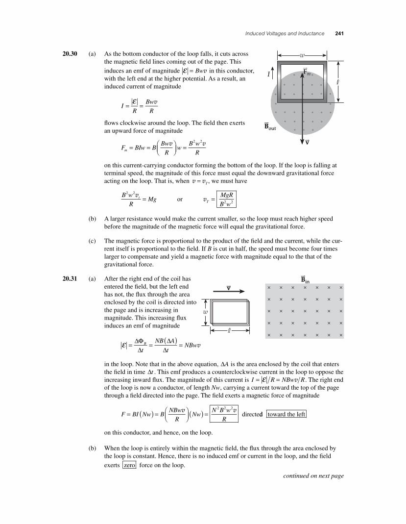
20.30 (a) As the bottom conductor of the loop falls, it cuts across the magnetic fi eld lines coming out of the page. This
induces an emf of magnitude ε = Bwv in this conductor, with the left end at the higher potential. As a result, an induced current of magnitude
IR
Bw
R= =
ε v
fl ows clockwise around the loop. The fi eld then exerts an upward force of magnitude
F BIw B
Bw
Rw
B w
Rm = = ⎛⎝⎜
⎞⎠⎟ =v v2 2
on this current-carrying conductor forming the bottom of the loop. If the loop is falling at terminal speed, the magnitude of this force must equal the downward gravitational force acting on the loop. That is, when v v= T , we must have
B w
RMgt
2 2v = or vT
MgR
B w= 2 2
(b) A larger resistance would make the current smaller, so the loop must reach higher speed before the magnitude of the magnetic force will equal the gravitational force.
(c) The magnetic force is proportional to the product of the fi eld and the current, while the cur-rent itself is proportional to the fi eld. If B is cut in half, the speed must become four times larger to compensate and yield a magnetic force with magnitude equal to the that of the gravitational force.
20.31 (a) After the right end of the coil has entered the fi eld, but the left end has not, the fl ux through the area enclosed by the coil is directed into the page and is increasing in magnitude. This increasing fl ux induces an emf of magnitude
ε = =
( ) =ΔΦΔ
ΔΔ
B
t
NB A
tNBwv
in the loop. Note that in the above equation, ΔA is the area enclosed by the coil that enters the fi eld in time Δt . This emf produces a counterclockwise current in the loop to oppose the increasing inward fl ux. The magnitude of this current is I R NBw R= =ε v . The right end of the loop is now a conductor, of length Nw, carrying a current toward the top of the page through a fi eld directed into the page. The fi eld exerts a magnetic force of magnitude
F BI Nw B
NBw
RNw
N B w
R= ( ) = ⎛
⎝⎜⎞⎠⎟ ( ) =v v2 2 2
directedd toward the left
on this conductor, and hence, on the loop.
(b) When the loop is entirely within the magnetic fi eld, the fl ux through the area enclosed by the loop is constant. Hence, there is no induced emf or current in the loop, and the fi eld
exerts zero force on the loop.
continued on next page
56157_20_ch20_p219-251.indd 24156157_20_ch20_p219-251.indd 241 3/19/08 4:05:53 AM3/19/08 4:05:53 AM
242 Chapter 20
(c) After the right end of the loop emerges from the fi eld, and before the left end emerges, the fl ux through the loop is directed into the page and decreasing. This decreasing fl ux induces an emf of magnitude ε = NBwv in the loop, which produces an induced current directed clockwise around the loop so as to oppose the decreasing fl ux. The current has magnitude I R NBw R= =ε v . This current fl owing upward, through conductors of total length Nw, in the left end of the loop, experiences a magnetic force given by
F BI Nw B
NBw
RNw
N B w
R= ( ) = ⎛
⎝⎜⎞⎠⎟ ( ) =v v2 2 2
directedd toward the left
20.32 (a) The motional emf induced in the bar must be ε = IR , where I is the current in this series circuit. Since ε = ⊥B lv , the speed of the moving bar must be
v = = =
×( )( )( )⊥ ⊥
−εB
IR
Bl l
8 5 10 9 0
0 30 0 3
3. .
. .
A
T
Ω55
0 73 m
m s( ) = .
The fl ux through the closed loop formed by the rails, the bar, and the resistor is directed into the page and is increasing in magnitude. To oppose this change in fl ux, the current must fl ow in a manner so as to produce fl ux out of the page through the area enclosed by the loop. This means the current will fl ow counterclockwise .
(b) The rate at which energy is delivered to the resistor is
P = = ×( ) ( ) = × =− −I R2 3 2 48 5 10 9 0 6 5 10 0 65. . . . A W Ω mmW mJ s= 0 65.
(c) An external force directed to the right acts on the bar to balance the magnetic force to the
left. Hence, work is being done by the external force , which is transformed into the resis-
tor’s thermal energy.
20.33 The emf induced in a rotating coil is directly proportional to the angular frequency of the coil. Thus,
εε
ωω
2
1
2
1
= or ε εωω2
2
11
500
9002=
⎛⎝⎜
⎞⎠⎟
=⎛⎝⎜
⎞⎠⎟
rev min
rev min44 0 13 3. . V V( ) =
20.34 ε ωmax horizontal T m= = ×( )( )−NB A 100 2 0 10 0 205. .22
15002 1
rev
min
rad
1 rev
min
60⎛⎝⎜
⎞⎠⎟
⎛⎝⎜
⎞⎠⎟
π s
V mV
⎛⎝⎜
⎞⎠⎟
⎡⎣⎢
⎤⎦⎥
= × =−1 3 10 132.
20.35 Note the similarity between the situation in this problem and a generator. In a generator, one nor-mally has a loop rotating in a constant magnetic fi eld so the fl ux through the loop varies sinusoi-dally in time. In this problem, we have a stationary loop in an oscillating magnetic fi eld, and the fl ux through the loop varies sinusoidally in time. In both cases, a sinusoidal emf ε ε ω= max sin t where ε ωmax = NBA is induced in the loop.
The loop in this case consists of a single band N =( )1 around the perimeter of a red blood cell with diameter d = × −8 0 10 6. m. The angular frequency of the oscillating fl ux through the area of this loop is ω π π π= = ( ) =2 2 60 120f Hz rad s. The maximum induced emf is then
ε ω π ω
πmax
. .= =
⎛⎝⎜
⎞⎠⎟
=×( ) ×− −
NBA Bd 2 3
4
1 0 10 8 0 10 T 66 2
11120
41 9 10
m s V
1( ) ( )= ×
−−π
.
56157_20_ch20_p219-251.indd 24256157_20_ch20_p219-251.indd 242 3/19/08 1:50:08 AM3/19/08 1:50:08 AM
Induced Voltages and Inductance 243
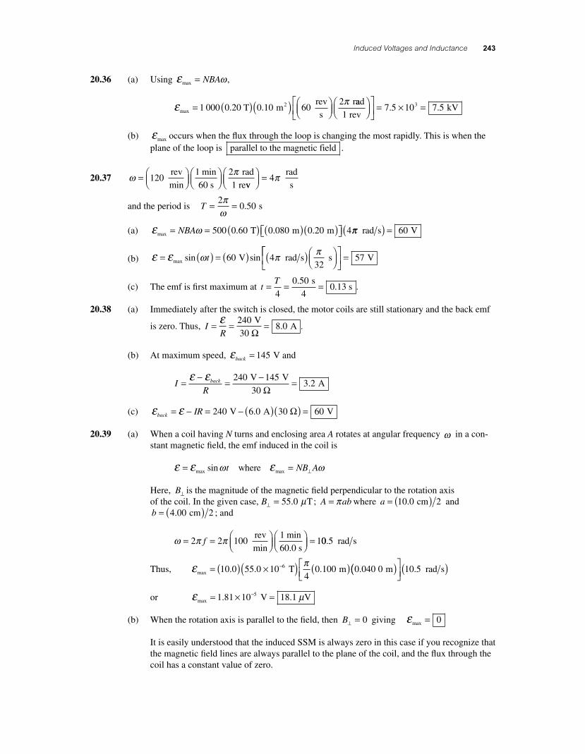
20.36 (a) Using ε ωmax = NBA ,
ε π
max .20 T m 0 rev
s
r= ( )( ) ⎛⎝⎜
⎞⎠⎟1 000 0 0 10 6
22.aad
1 rev kV⎛
⎝⎜⎞⎠⎟
⎡⎣⎢
⎤⎦⎥
= × =7 5 10 7 53. .
(b) εmax occurs when the fl ux through the loop is changing the most rapidly. This is when the plane of the loop is parallel to the magnetic field .
20.37 ω π= ⎛⎝⎜
⎞⎠⎟
⎛⎝⎜
⎞⎠⎟120
1 2
rev
min
min
60 s
rad
1 revv
rad
s⎛⎝⎜
⎞⎠⎟ = 4π
and the period is T = =20 50
πω
. s
(a) ε ωmax T m m= = ( ) ( )( )⎡⎣ ⎤⎦NBA 500 0 60 0 080 0 20 4. . . ππ rad s V( ) = 60
(b) ε ε ω π π= ( ) = ( ) ( )⎛⎝⎜
⎞⎠⎟max V rad s ssin sint 60 4
32⎡⎡⎣⎢
⎤⎦⎥
= 57 V
(c) The emf is fi rst maximum at tT= = =4
0 500 13
..
s
4 s .
20.38 (a) Immediately after the switch is closed, the motor coils are still stationary and the back emf
is zero. Thus, IR
= = =ε 2408 0
V
30 A
Ω. .
(b) At maximum speed, εback = 145 V and
I
Rback= − = − =ε ε 240 145
3 2 V V
30 A
Ω.
(c) ε εback IR= − = − ( )( ) =240 6 0 60 V A 30 V. Ω
20.39 (a) When a coil having N turns and enclosing area A rotates at angular frequency ω in a con-stant magnetic fi eld, the emf induced in the coil is
ε ε εω ω= = ⊥max maxsin t NB Awhere
Here, B⊥ is the magnitude of the magnetic fi eld perpendicular to the rotation axis of the coil. In the given case, B⊥ = 55 0. Tμ ; A ab= π where a = ( )10 0 2. cm and b = ( )4 00 2. cm ; and
ω π π= = ⎛
⎝⎜⎞⎠⎟
⎛⎝⎜
⎞⎠⎟ =2 2 100
11f
rev
min
min
60.0 s00 5. rad s
Thus, ε πmax . . . .= ( ) ×( ) ( )−10 0 55 0 10
40 100 0 040 06 T m m(( )⎡
⎣⎢⎤⎦⎥( )10 5. rad s
or ε μmax . .= × =−1 81 10 18 15 V V
(b) When the rotation axis is parallel to the fi eld, then B⊥ = 0 giving εmax = 0
It is easily understood that the induced SSM is always zero in this case if you recognize that the magnetic fi eld lines are always parallel to the plane of the coil, and the fl ux through the coil has a constant value of zero.
56157_20_ch20_p219-251.indd 24356157_20_ch20_p219-251.indd 243 3/19/08 1:50:08 AM3/19/08 1:50:08 AM
244 Chapter 20
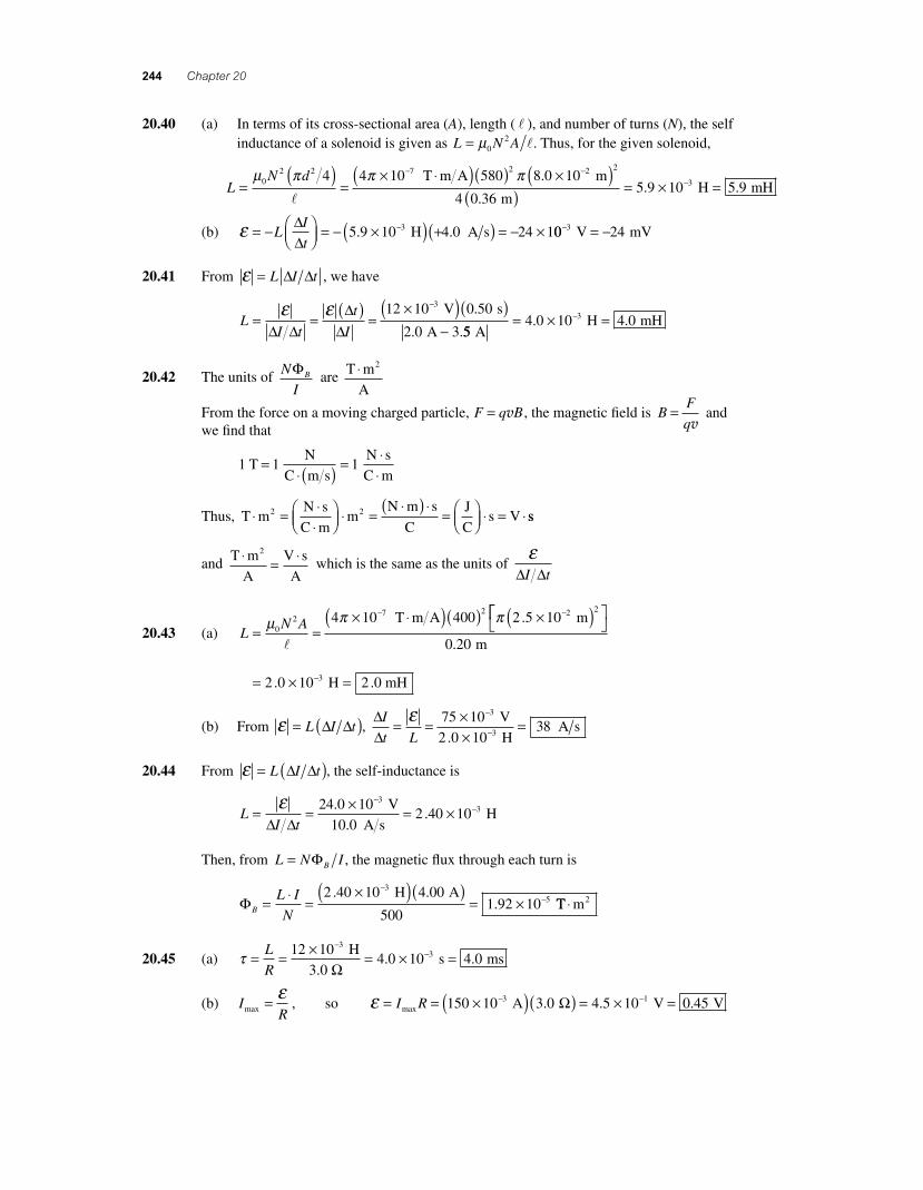
20.40 (a) In terms of its cross-sectional area (A), length ( l ), and number of turns (N), the self inductance of a solenoid is given as L N A= μ0
2 l. Thus, for the given solenoid,
L
N d=
( )=
× ⋅( )( ) ×− −μ π π π02 2 7 24 4 10 580 8 0 10
l
T m A2
. m
m H mH
( )( ) = × =−
2
3
4 0 365 9 10 5 9
.. .
(b) ε = − ⎛⎝⎜
⎞⎠⎟ = − ×( ) +( ) = − ×−L
I
t
ΔΔ
5 9 10 4 0 24 13. . H A s 00 243− = − V mV
20.41 From ε = L I tΔ Δ , we have
L
I t
t
I= =
( )=
×( )( )−
−ε εΔ Δ
ΔΔ
12 10 0 50
2 0 3
3 V s
A
.
. .554 0 10 4 03
A H mH= × =−. .
20.42 The units of N
IBΦ are T m
A
2⋅
From the force on a moving charged particle, F q B= v , the magnetic fi eld is BF
q=
v and
we fi nd that
1 1 1 T
N
C m s
N s
C m=
⋅( ) = ⋅⋅
Thus, T mN s
C mm
N m s
C
J
Cs V2 2⋅ = ⋅
⋅⎛⎝⎜
⎞⎠⎟ ⋅ =
⋅( ) ⋅= ⎛
⎝⎜⎞⎠⎟ ⋅ = ⋅ ss
and T m
A
V s
A
2⋅ = ⋅ which is the same as the units of ε
Δ ΔI t
20.43 (a) LN A= =
× ⋅( )( ) ×( )− −μ π π
02
7 2 2 24 10 400 2 5 10
l
T m A m.⎡⎡⎣
⎤⎦
= × =−
0 20
2 0 10 3
.
.
m
H 2.0 mH
(b) From ε = ( )L I tΔ Δ , ΔΔ
I
t L= = ×
×=
−
−
ε 75 10
108
3
3
V
2 .0 H3 A s
20.44 From ε = ( )L I tΔ Δ , the self-inductance is
LI t
= = × = ×−
−εΔ Δ
24 0 102 40 10
33.
. V
10.0 A s H
Then, from L N IB= Φ , the magnetic fl ux through each turn is
ΦB
L I
N= ⋅ =
×( )( )= ×
−−2 40 10 4 00
1 92 103
5. .
. H A
500 TT m2⋅
20.45 (a) τ = = × = × =−
−L
R
12 104 0 10 4 0
33 H
3.0 s ms
Ω. .
(b) IRmax = ε
, so ε = = ×( )( ) = × =− −I Rmax . . .150 10 3 0 4 5 10 0 453 1 A VΩ V
56157_20_ch20_p219-251.indd 24456157_20_ch20_p219-251.indd 244 3/19/08 1:50:09 AM3/19/08 1:50:09 AM
Induced Voltages and Inductance 245
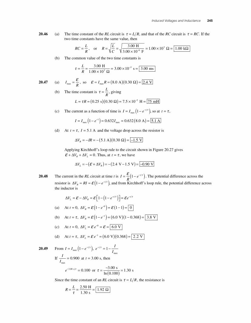
20.46 (a) The time constant of the RL circuit is τ = L R, and that of the RC circuit is τ = RC. If the two time constants have the same value, then
RCL
R= , or R
L
C= =
×= × =−
3 001 00 10 1 003.
. . H
3.00 10 F k6 Ω Ω
(b) The common value of the two time constants is
τ = =
×= × =−L
R
3 003 00 3 00
.. .
H
1.00 10 10 s ms3
3
Ω
20.47 (a) IRmax = ε
, so ε = = ( )( ) =I Rmax . . .8 0 0 30 2 4 A VΩ
(b) The time constant is τ = L
R, giving
L R= = ( )( ) = × =−τ 0 25 0 30 7 5 10 752. . . s H mHΩ
(c) The current as a function of time is I I e t= −( )−max 1 τ , so at t = τ ,
I I e I= −( ) = = ( ) =−max max. . . .1 0 632 0 632 8 0 5 11 A A
(d) At t = τ , I = 5 1. A and the voltage drop across the resistor is
Δ ΩV IRR = − = − ( )( ) = −5 1 0 30 1 5. . . A V
Applying Kirchhoff’s loop rule to the circuit shown in Figure 20.27 gives ε + + =Δ ΔV VR L 0. Thus, at t = τ , we have
Δ ΔV VL R= − +( ) = − −( ) = −ε 2 4 1 5 0 90. . . V V V
20.48 The current in the RL circuit at time t is IR
e t= −( )−ε τ1 . The potential difference across the
resistor is ΔV RI eRt= = −( )−ε τ1 , and from Kirchhoff’s loop rule, the potential difference across
the inductor is
Δ ΔV V e eL Rt t= − = − −( )⎡⎣ ⎤⎦ =− −ε ε ετ τ1 1
(a) At t = 0, ΔV eR = −( ) = −( ) =−ε ε1 1 1 00
(b) At t = τ , ΔV eR = −( ) = ( ) −( ) =−ε 1 6 0 1 0 368 3 81 . . . V V
(c) At t = 0, ΔV eL = = =−ε ε0 6 0. V
(d) At t = τ , ΔV eL = = ( )( ) =−ε 1 6 0 0 368 2 2. . . V V
20.49 From I I e t= −( )−max 1 τ , e
I
It− = −τ 1
max
If I
Imax
= 0 900. at t = 3 00. s, then
e− =3 00 0 100. . s τ or τ = −( ) =3 00
0 1001 30
.
ln ..
s s
Since the time constant of an RL circuit is τ = L R , the resistance is
RL= = =τ
2 50
1 301 92
.
..
H
s Ω
56157_20_ch20_p219-251.indd 24556157_20_ch20_p219-251.indd 245 3/19/08 1:50:10 AM3/19/08 1:50:10 AM
246 Chapter 20
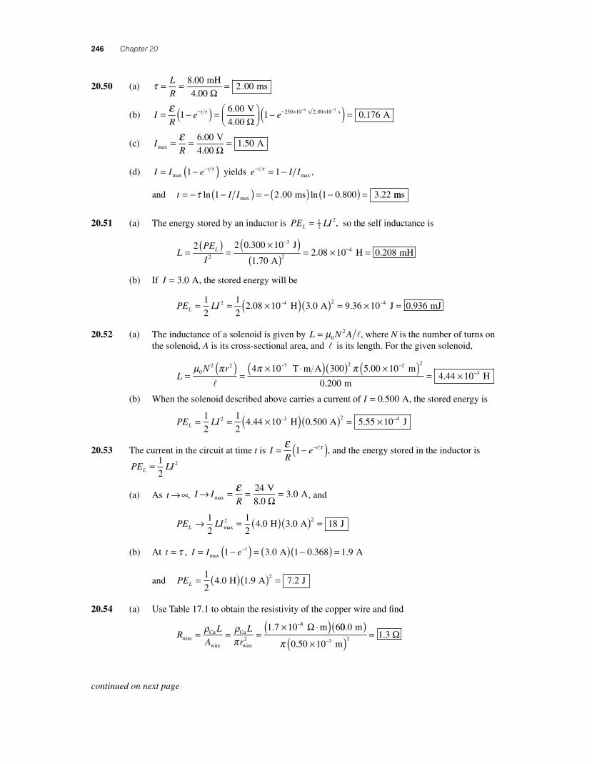
20.50 (a) τ = = =L
R
8 002 00
..
mH
4.00 ms
Ω
(b) IR
e et= −( ) = ⎛⎝⎜
⎞⎠⎟ −− − × −ε τ1
6 001 250 10 6. V
4.00 Ω s 2.00 10 s3
A× −( ) = 0 176.
(c) IRmax
V
4.00 A= = =ε 6 00
1 50.
.Ω
(d) I I e t= −( )−max 1 τ yields e I It− = −τ 1 max ,
and t I I= − −( ) = − ( ) −( ) =τ ln . ln . .1 2 00 1 0 800 3 22max ms mms
20.51 (a) The energy stored by an inductor is PE LIL = 12
2, so the self inductance is
LPE
IL=
( )=
×( )( )
= ×−2 2 0 300 10
1 702 08 102
3
2
.
..
J
A−− =4 0 208 H mH.
(b) If I = 3 0. A, the stored energy will be
PE LIL = = ×( )( ) = ×− −1
2
1
22 08 10 3 0 9 36 102 4 2 4. . . H A J mJ= 0 936.
20.52 (a) The inductance of a solenoid is given by L N A= μ02 l, where N is the number of turns on
the solenoid, A is its cross-sectional area, and l is its length. For the given solenoid,
LN r
=( )
=× ⋅( )( ) ×− −μ π π π0
2 2 7 2 24 10 300 5 00 10
l
T m A . m
m H
( )= × −
2
3
0 2004 44 10
..
(b) When the solenoid described above carries a current of I = 0 500. A, the stored energy is
PE LIL = = ×( )( ) = ×−1
2
1
24 44 10 0 500 5 55 102 3 2
. . . H A −−4 J
20.53 The current in the circuit at time t is IR
e t= −( )−ε τ1 , and the energy stored in the inductor is
PE LIL = 1
22
(a) As t → ∞, I IR
→ = = =max
V
8.0 A
ε 243 0
Ω. , and
PE LIL → = ( )( ) =1
2
1
24 0 3 0 182 2
max H A J. .
(b) At t = τ , I I e= −( ) = ( ) −( ) =−max A A1 3 0 1 0 368 1 91 . . .
and PEL = ( )( ) =1
24 0 1 9 7 2
2. . . H A J
20.54 (a) Use Table 17.1 to obtain the resistivity of the copper wire and fi nd
RL
A
L
rwireCu
wire
Cu
wire
m= = =
× ⋅( )−ρ ρπ 2
81 7 10 6. Ω 00 0
101 32
..
m
0.50 m
3
( )×( )
=−π
Ω
continued on next page
56157_20_ch20_p219-251.indd 24656157_20_ch20_p219-251.indd 246 3/19/08 4:05:27 AM3/19/08 4:05:27 AM
Induced Voltages and Inductance 247
(b) NL L
r= = =
Circumference of a loop solenoid2
60
π.00
104 8 102 m
2 2.0 m turns
2π ×( ) = ×− .
(c) The length of the solenoid is
l = ( ) = ( ) = ( ) ×N N rdiameter of wire wire2 480 2 0 50. 110 0 483−( ) = m m.
(d) LN A N r= = =
× −μ μ π π0
20
2 2 74 10solenoid solenoid
T
l l
⋅⋅( )( ) ×( )−m A m
m
480 2 0 10
0 48
2 2 2π .
.
giving L = × =−7 6 10 0 764. . H mH
(e) τ = =+
= ×+
−L
R
L
R rtotal wire internal
H
1.3
7 6 10 4.
Ω 00 3504 6 10 0 464
.. .
s ms
Ω= × =−
(f) IRmax
.
..= =
+=ε
total
V
1.3 A
6 0
0 3503 6
Ω Ω
(g) I I e t= −( )−max 1 τ , so when I I= 0 999. max
, we have 1 0 999− =−e t τ . and
e t− = − =τ 1 0 999 0 001. . . Thus, − = ( )t
τln .0 001 or t = − ⋅ ( )τ ln .0 001
giving t = − ( ) ⋅ ( ) =0 46 0 001 3 2. ln . . ms ms
(h) PE LIL( ) = = ×( )( ) =−max max . . .
1
2
1
27 6 10 3 6 42 4 2
H A 99 10 4 93× =− J mJ.
20.55 According to Lenz’s law, a current will be induced in the coil to oppose the change in magnetic fl ux due to the magnet. Therefore, current must be directed from b to a through the resistor, and
V Va b− will be negative .
20.56 ε θ= =
( )⎡⎣ ⎤⎦ΔΦΔ
ΔΔ
B
t
NBA
t
cos, so B
t
NA=
⋅( )⎡⎣ ⎤⎦
εθ
ΔΔ cos
or B =( ) ×( )( )⎡⎣ ⎤⎦
−0 166 2 77 10
500 0 150 4
3
2
. .
.
V s
mπ ccos cos. .
0 905 20 10 52 05
° °−[ ]= × =− T Tμ
20.57 (a) The current in the solenoid reaches I I= 0 632. max in a time of t L R= =τ , where
LN A= =
× ⋅( )( ) ×− −μ π0
2 7 2 44 10 12 500 1 00 10
l
T m A m2.(( )×
=−7.00 10 m H2 0 280.
Thus, t = = × =−0 2802 00 10 20 02.
. . H
14.0 s ms
Ω
(b) The change in the solenoid current during this time is
Δ ΔI I
V
R= − = ⎛
⎝⎜⎞⎠⎟ =0 632 0 0 632 0 632
60 0
14. . .
.max
V
...
02 71
A
Ω⎛⎝⎜
⎞⎠⎟ =
so the average back emf is
εback 2 H A
2.00 10 = ⎛
⎝⎜⎞⎠⎟ = ( )
× −LI
t
ΔΔ
0 2802 71
..
ss V
⎛⎝⎜
⎞⎠⎟
= 37 9.
continued on next page
56157_20_ch20_p219-251.indd 24756157_20_ch20_p219-251.indd 247 3/19/08 4:05:33 AM3/19/08 4:05:33 AM
248 Chapter 20
(c) ΔΦΔ
ΔΔ
ΔΔ
ΔΔ
B
t
B A
t
n I A
t
N I A=
( ) =( )⎡⎣ ⎤⎦ =
( )⋅
12 0 0
2μ μ
l tt( )
=× ⋅( )( )( ) ×− −4 10 12 500 2 71 1 00 107 4π T m A A. . m
7.00 10 m 2.00 10 s
2
2 2
( )×( ) ×( ) = ×− −
−
21 52 10 3. V
(d) IR
N t
RB= =
( )=
( ) ×εcoil
coil
coil
coil
ΔΦ Δ 820 1 52 10. −−( )= =
3
0 051 9 51 9 V
24.0 A mA
Ω. .
20.58 (a) The gravitational force exerted on the ship by the pulsar supplies the centripetal accelera-
tion needed to hold the ship in orbit. Thus, FGM m
r
m
rg = =pulsar ship
orbit
ship
orbit2
2v, giving
v = =× ⋅( ) ×−GM
rpulsar
orbit
2 N m kg6 67 10 2 0 1011 3. . 00
76
3 0 102 1 10
kg
m m s
( )×
= ×.
.
(b) The magnetic force acting on charged particles moving through a magnetic fi eld is perpen-dicular to both the magnetic fi eld and the velocity of the particles (and therefore perpen-dicular to the ship’s length). Thus, the charged particles in the materials making up the spacecraft experience magnetic forces directed from one side of the ship to the other, mean-ing that the induced emf is directed from side to side within the ship.
(c) ε = ⊥B lv , where l = = =2 0 080 80rship km m. is the side to side dimension of the ship. This yields
ε = ×( )( ) ×( ) = ×1 0 10 80 2 1 10 1 7 102 6 10. . . T m m s V
(d) The very large induced emf would lead to powerful spontaneous electric discharges. The strong electric and magnetic fi elds would disrupt the fl ow of ions in their bodies.
20.59 (a) To move the bar at uniform speed, the magnitude of the applied force must equal that of the magnetic force retarding the motion of the bar. Therefore, F B Iapp = l. The magnitude of the induced current is
IR
t
R
B A t
R
B
RB= =
( )=
( )=
ε ΔΦ Δ Δ Δ lv
so the fi eld strength is BIR=lv
, giving F I Rapp = 2 v
Thus, the current is
IF
R=
⋅=
( )( )=app N m s
8.00 A
v 1 00 2 000 500
. ..
Ω
(b) P = = ( ) ( ) =I R2 20 500 8 00 2 00. . . A WΩ
(c) Pinput app N m s W= ⋅ = ( )( ) =F v 1 00 2 00 2 00. . .
56157_20_ch20_p219-251.indd 24856157_20_ch20_p219-251.indd 248 3/19/08 1:50:13 AM3/19/08 1:50:13 AM
Induced Voltages and Inductance 249
20.60 (a) When the motor is fi rst turned on, the coil is not rotating so the back emf is zero. Thus, the current is a maximum with only the resistance of the windings limiting its value. This gives I Rmax = ε , or
RI
= = =εmax
12011
V
11 A Ω
(b) When the motor has reached maximum speed, the steady state value of the current is I R= −( )ε εback , giving the back emf as
ε εback V A V= − = − ( )( ) =IR 120 4 0 11 76. Ω
20.61 If d is the distance from the lightning bolt to the center of the coil, then
ε μ π μav =
( )=
( ) =( )⎡⎣ ⎤⎦ =
N
t
N B A
t
N I d A
t
NBΔΦΔ
ΔΔ
ΔΔ
0 02 ΔΔ
ΔI A
d t
( )( )
=× ⋅( ) × −−
2
100 4 10 6 02 10 07 6
π
π T m A A.(( ) ( )⎡⎣ ⎤⎦( ) ×( )
=
−
π
π
0 800
2 200 10 5 10
1
2
6
.
.
.
m
m s
115 10 1155× = V kV
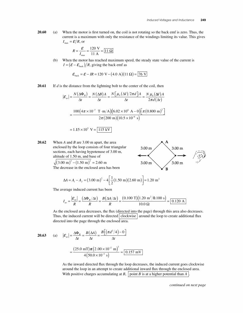
20.62 When A and B are 3.00 m apart, the area enclosed by the loop consists of four triangular sections, each having hypotenuse of 3.00 m, altitude of 1.50 m, and base of
3 00 1 50 2 602 2
. . . m m m( ) − ( ) = The decrease in the enclosed area has been
ΔA A Ai f= − = ( ) − ( )( )⎡⎣⎢
⎤⎦
3 00 41
21 50 2 60
2. . . m m m ⎥⎥ = 1 20. m2
The average induced current has been
IR
t
R
B A t
RB
avav
2 T m= =
( )=
( )=
( )ε ΔΦ Δ Δ Δ 0 100 1 20. . 00 1000 120
..
s
10.0 A
( )=
Ω
As the enclosed area decreases, the fl ux (directed into the page) through this area also decreases. Thus, the induced current will be directed clockwise around the loop to create additional fl ux directed into the page through the enclosed area.
20.63 (a) επ
av
mT
= =( ) =
( ) −⎡⎣ ⎤⎦
=( )
ΔΦΔ
ΔΔ Δ
B
t
B A
t
B d
t
2 4 0
25 0. ππ 2
4 50 0 100 157
2
3
.00 10 m
s mV
2×( )×( ) =
−
−..
As the inward directed fl ux through the loop decreases, the induced current goes clockwise around the loop in an attempt to create additional inward fl ux through the enclosed area. With positive charges accumulating at B, point is at a higher potential than B A .
continued on next page
56157_20_ch20_p219-251.indd 24956157_20_ch20_p219-251.indd 249 3/19/08 4:45:01 AM3/19/08 4:45:01 AM
250 Chapter 20
(b) ε πav
mT .00 10= = ( ) =
−( )⎡⎣ ⎤⎦ ×ΔΦΔ
ΔΔ
B
t
B A
t
100 25 0 2. −−
−
( )×( ) =
2 m
s mV
2
34 4 00 105 89
..
As the inward directed fl ux through the enclosed area increases, the induced current goes counterclockwise around the loop in an attempt to create fl ux directed outward through the enclosed area.
With positive charges now accumulating at A, point is at a higher potential than A B .
20.64 The induced emf in the ring is
εavsolenoid solenoid sol= =
( ) =( )ΔΦ
ΔΔ
ΔΔ
B
t
B A
t
B A2 eenoid solenoidsoleΔ
ΔΔt
nI
tA= ⎛
⎝⎜⎞⎠⎟
⎡⎣⎢
⎤⎦⎥
1
2 0μ nnoid
T m A A s= × ⋅( )( )( ) ×−1
24 10 1 000 270 3 00 17π π . 00 4 80 102 2 4− −⎡⎣ ⎤⎦( )⎡
⎣⎢⎤⎦⎥
= × m V.
Thus, the induced current in the ring is
IRringav
4
V
3.00 10 A= = ×
×=
−
−
ε 4 80 101 60
4..
Ω
20.65 (a) As the rolling axle (of length l = 1 50. m) moves perpendicularly to the uniform magnetic fi eld, an induced emf of magnitude ε = Blv will exist between its ends. The current pro-duced in the closed-loop circuit by this induced emf has magnitude
IR
t
R
B A t
R
B
RB= =
( )=
( )= =
( )εav TΔΦ Δ Δ Δ lv 0 800 1 50. . m m s
. A
( )( )=
3 00
0 4009 00
..
Ω
(b) The induced current through the axle will cause the magnetic fi eld to exert a retarding force of magnitude F BIr = l on the axle. The direction of this force will be opposite to that of the velocity
rv so as to oppose the motion of the axle. If the axle is to continue moving at
constant speed, an applied force in the direction of rv and having magnitude F Frapp = must
be exerted on the axle.
F BIapp T A m N= = ( )( )( ) =l 0 800 9 00 1 50 10 8. . . .
(c) Using the right-hand rule, observe that positive charges within the moving axle experi-ence a magnetic force toward the rail containing point b, and negative charges experience a force directed toward the rail containing point a. Thus, the rail containing b will be positive relative to the other rail. Point b a is then at a higher potential than , and the current goes from b to a through the resistor R.
(d) No . Both the velocity rv of the rolling axle and the magnetic fi eld
rB are unchanged. Thus,
the polarity of the induced emf in the moving axle is unchanged, and the current continues to be directed from b to a through the resistor R.
56157_20_ch20_p219-251.indd 25056157_20_ch20_p219-251.indd 250 3/19/08 4:04:31 AM3/19/08 4:04:31 AM
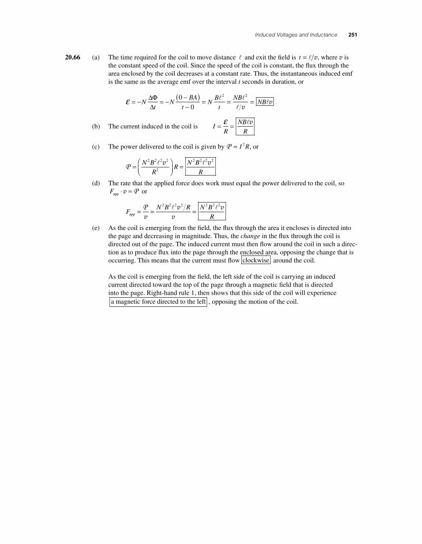
Induced Voltages and Inductance 251
20.66 (a) The time required for the coil to move distance l and exit the fi eld is t = l v, where v is the constant speed of the coil. Since the speed of the coil is constant, the fl ux through the area enclosed by the coil decreases at a constant rate. Thus, the instantaneous induced emf is the same as the average emf over the interval t seconds in duration, or
ε = − = −−( )−
= = =Nt
NBA
tN
B
t
NBNB
ΔΦΔ
0
0
2 2l l
ll
vv
(b) The current induced in the coil is IR
NB
R= =ε lv
(c) The power delivered to the coil is given by P = I R2 , or
P =⎛⎝⎜
⎞⎠⎟
=N B
RR
N B
R
2 2 2 2
2
2 2 2 2l lv v
(d) The rate that the applied force does work must equal the power delivered to the coil, so Fapp ⋅ =v P or
FN B R N B
Rapp = = =Pv
vv
v2 2 2 2 2 2 2l l
(e) As the coil is emerging from the fi eld, the fl ux through the area it encloses is directed into the page and decreasing in magnitude. Thus, the change in the fl ux through the coil is directed out of the page. The induced current must then fl ow around the coil in such a direc-tion as to produce fl ux into the page through the enclosed area, opposing the change that is occurring. This means that the current must fl ow clockwise around the coil.
As the coil is emerging from the fi eld, the left side of the coil is carrying an induced current directed toward the top of the page through a magnetic fi eld that is directed into the page. Right-hand rule 1, then shows that this side of the coil will experience a magnetic force directed to the left , opposing the motion of the coil.
56157_20_ch20_p219-251.indd 25156157_20_ch20_p219-251.indd 251 3/19/08 1:50:14 AM3/19/08 1:50:14 AM