Embed Size (px)
Citation preview
Copyright © Bellateq, Ltd. 2013. All Rights Reserved
Page | 1
SECTION 4 – TESTING & QUALITY CONTROL
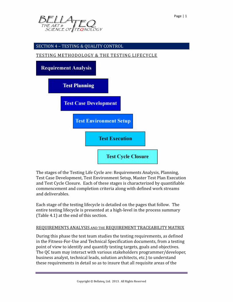
TESTING METHODOLOGY & THE TESTING LIFECYCLE
The stages of the Testing Life Cycle are: Requirements Analysis, Planning, Test Case Development, Test Environment Setup, Master Test Plan Execution and Test Cycle Closure. Each of these stages is characterized by quantifiable commencement and completion criteria along with defined work streams and deliverables. Each stage of the testing lifecycle is detailed on the pages that follow. The entire testing lifecycle is presented at a high-level in the process summary (Table 4.1) at the end of this section.
REQUIREMENTS ANALYSIS AND THE REQUIREMENT TRACEABILITY MATRIX
- -
Copyright © Bellateq, Ltd. 2013. All Rights Reserved
Page | 2
-
The RTM should serve as the cross-reference – the point of intersection – of the functionality of the software (as defined in the FFU) and the test process designed to ensure that the software can be used in the manner for which it is intended (that it is fit for use). A traceability matrix is a table that connects a functional requirement of the software to the tests that are needed to verify that the requirement is fulfilled. A good traceability matrix will provide backward and forward traceability, (a requirement can be traced to a test and a test to a requirement). In addition to serving as the cross reference between functions and functional testing, the RTM links high-level requirements, design specifications, test requirements and code files to each other, where appropriate. In this capacity, the RTM serves as a map providing the information necessary for understanding where information is located. This information is particularly valuable as a “lesson learned” and as an input for future design, development and testing processes. The fundamental goal of the RTM is to make sure that all features are tested and that all test processes are tied back to a feature.
Preparation of Requirement Traceability Matrix (RTM). Identification of the testing approach, targets, goals and objectives Setting of testing priorities, success measures and pass/fail
thresholds Identification of automated versus manual test processes
TEST PROCESS PLANNING
The Test Strategy document is an artifact created by the test leader to provide the details of a systematic test process and cadence. This high-level, strategic document includes testing human resource requirements, process timeline estimates, interim deliverable target dates and the overall test life cycle timeline as driven by the scope of the testing effort. This scope
Copyright © Bellateq, Ltd. 2013. All Rights Reserved
Page | 3
definition should synchronize with and use as inputs all content from the Fitness-For-Use and Technical Specification documentation provided by the development leader. Key work streams at this stage of testing include:
Project scope and expectations definition Technology and methodology selection and detailed definition Preparation of the Master Test Plan including:
o Test Cases o Use Cases o Tester Role Definitions and Security Protocols
Testing effort resource requirement estimation Definition of quantifiable, measurable pass/fail thresholds and
success measures Resource Plan (Load Balancing Plan) and identification of roles
and responsibility across the testing team Testing management tool(s) configuration and setup
TEST CASE DEVELOPMENT
After the programming and development team has reached a state of requirement freeze and with a clear understanding of the Fitness-For-Use and Technical Specification documents, the testing team begins creation and definition of test cases, test scripts and use case scenarios along with definition of the requisite test data necessary to facilitate execution of all test processes. It is during this phase that test case cadence is defined according to complexity, criticality and testing resource requirements. Key work streams at this stage of testing include:
Create test cases or Test scripts (if applicable). Categorization of Test Case. Create Test Data
Copyright © Bellateq, Ltd. 2013. All Rights Reserved
Page | 4
TEST ENVIRONMENT SETUP
A testing environment, separate from any development or production environments, consists of the following assets:
Test process infrastructure and hardware including: o Application Host Server o Application Test Data Server (if separate from host server)
Test process software including: o Host server(s) Operating System o Database populated with test data o Application software build(s) configured with appropriate
user security configurations o Front-end portal environment and browser o Any other software components required to effectively test
the application software build in a production-like mode.
It is the responsibility of the test team leader to ensure the conditions, infrastructures and environments necessary to support an effective testing effort are in place and that all pre-test criteria have been met before testing can be initiated. Key work streams at this stage of testing include:
Ensure that all hardware and software components of the testing infrastructure are in place, and ready for operation
--
TEST EXECUTION
Test Case execution is a process of performing the steps defined in test cases, test scripts and use cases in their logical sequence against specific test data while logged into the test environment with a variety of end-user security rights and privileges. If any test case, script or scenario fails, the testing team logs the bug in the defect tracking tool and goes through proper channels, as defined in the QC standard operating procedures, to report the defect to
Copyright © Bellateq, Ltd. 2013. All Rights Reserved
Page | 5
appropriate personnel on the programming and development team and track that defect through to satisfactory resolution. Concurrently with the execution of the master test plan, a dedicated team of developers should be correcting defects in preparation for release of the next application test build. Key work streams at this stage of testing include:
Execution of test cases, test scenarios and use cases Defect logging and tracking defined tool(s) Creation, verification and on-going update of test result
documentation including the daily testing dashboard Mapping of defects to test cases in Requirement Traceability
Matrix
For additional information regarding the types of tests executed during this phase of the testing life cycle, please refer to the “Testing Processes” section of this publication.
TEST CYCLE CLOSURE
Once all test cases, scenarios and use cases have met the exit criteria and success thresholds test cycle closure activities including: finalization of key deliverables, definition and documentation of lessons learned, calculation of test results and statistics and documents related to the project are finalized so that they can be used as reference and information inputs for future software development work streams. Finally, a Causal Analysis and Resolution (CAR) Report is prepared wherein best practices and defect cause analysis are detailed. Key work streams at this stage of testing include:
Test Metrics based on test coverage, resource cost Test Closure Report Analysis of test results including calculation of defect distribution
by module, function, defect type and defect severity Causal Analysis and Resolution (CAR) Report
Copyright © Bellateq, Ltd. 2013. All Rights Reserved
Page | 6
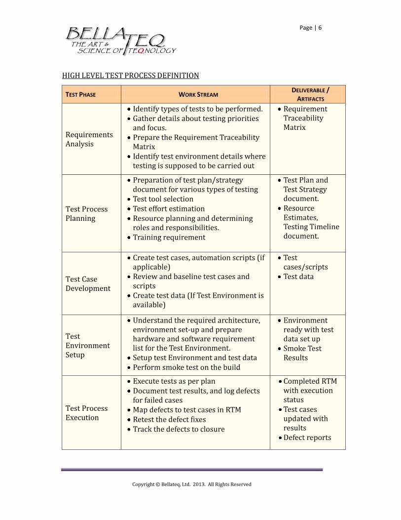
HIGH LEVEL TEST PROCESS DEFINITION
TEST PHASE WORK STREAM DELIVERABLE /
ARTIFACTS
Requirements Analysis
Test Process Planning
Test Case Development
Test Environment Setup
-
Test Process Execution

Copyright © Bellateq, Ltd. 2013. All Rights Reserved
Page | 7
TEST PHASE WORK STREAM DELIVERABLE /
ARTIFACTS
Test Cycle Closure
Table 4.1 – Test Process Summary
Copyright © Bellateq, Ltd. 2013. All Rights Reserved
Page | 8
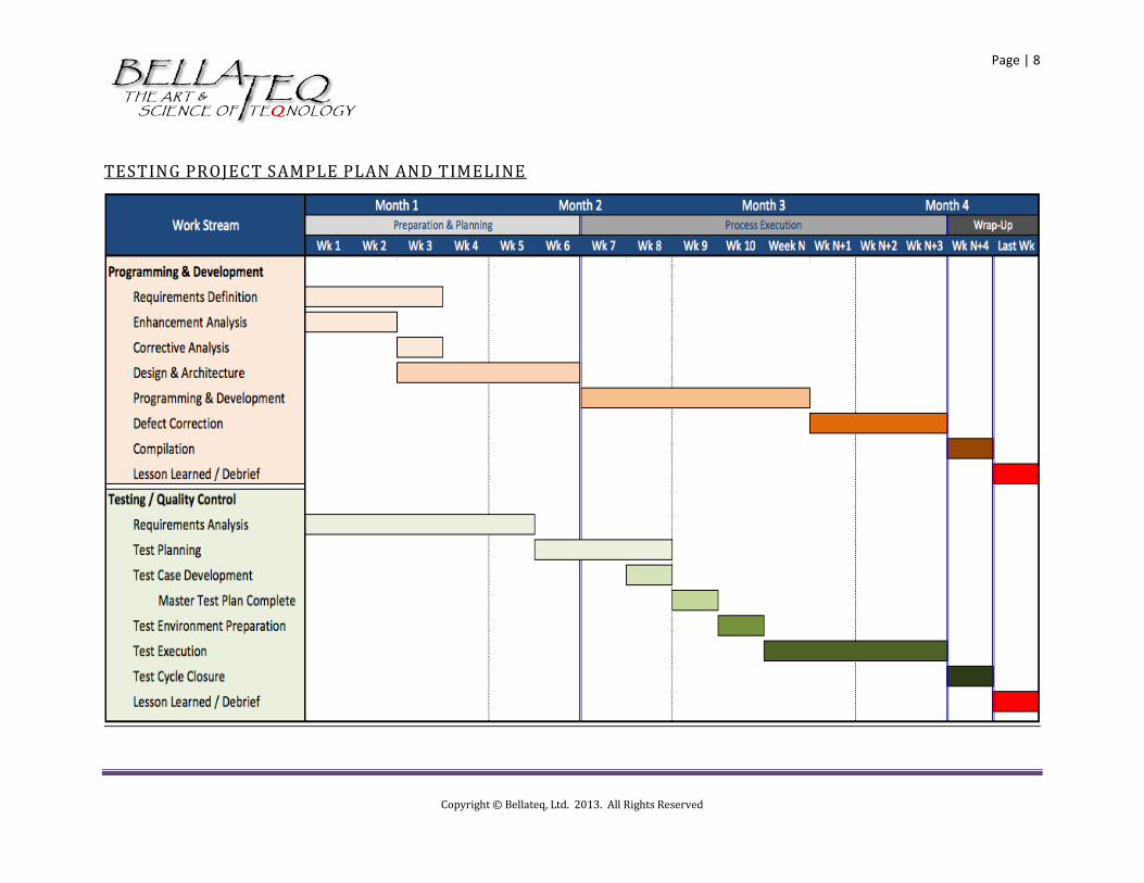
TESTING PROJECT SAMPLE PLAN AND TIMELINE

Copyright © Bellateq, Ltd. 2013. All Rights Reserved
Page | 9
REQUIREMENT TRACEABILITY MATRIX
Copyright © Bellateq, Ltd. 2013. All Rights Reserved
Page | 10
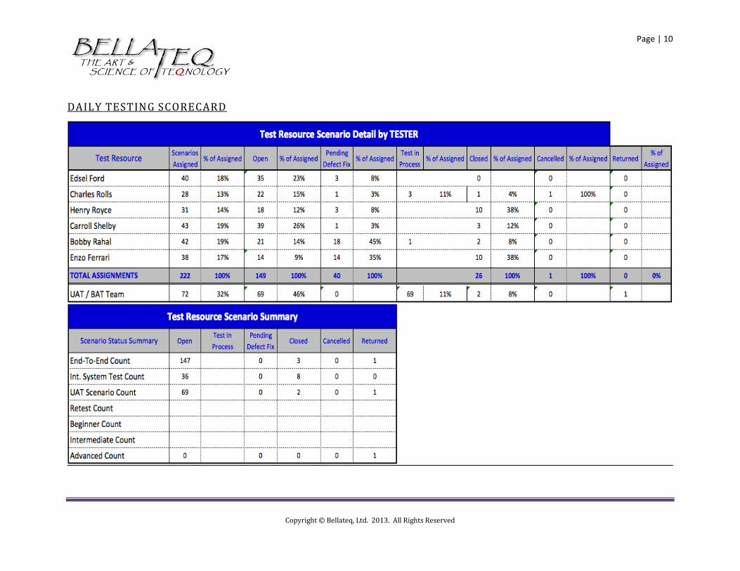
DAILY TESTING SCORECARD
Copyright © Bellateq, Ltd. 2013. All Rights Reserved
Page | 11
TESTING PROCESSES
During the course testing builds of software applications the development team and testing team will conduct a variety of types of test procedures. The primary test types relevant for the enterprise are as follows:
• Technical Testing • Functional Testing • Usability Testing • Unit Testing • Integration Testing • System Testing • Stress Testing • Performance Testing • Regression Testing • User Acceptance Testing • Beta Testing
Not every new release process requires every type of test and not all types of tests are executed on every application build. Each type of test is detailed in the following section and the testing roadmap detailing test cadence and test targets is presented as illustration 4.x herein.
FUNCTIONAL TESTING
Functional testing focuses on application functionality, as defined in the Fitness-For-Use document and as designed in the Technical Specification document. Where Unit and Integration testing focus on processes, Functional testing targets specific features of an application that, when combined, become the objects of Functional and Unit testing. USABILITY TESTING
Where all other tests focus on the functional capability of an application build Usability Testing focuses on the user interface of the build. Simply put, all other test types focus on whether or not the software works while Usability Testing focuses on whether or not the software can be used for the purpose for which it is intended by an “average” end user. UI standards including font formatting, color pallets, field-based, context-sensitive and system-level help and all other aspects of the application build designed to simplify user interaction and add to an application’s measure of intuitiveness and ease-of-use.
Copyright © Bellateq, Ltd. 2013. All Rights Reserved
Page | 12
UNIT TESTING
Unit testing is focuses on individual functional groups as defined by the test leader and development leader. Functional groups may be identified as specifically as a common menu items (example: all features under the “Transaction” menu versus all features under the “Reports” menu) or units may be identified as globally as all features within the “Residential Land” module versus the “Hunting Permits” module. As the development team is usually sub-divided according to vertical areas of expertise (printing for example) or horizontally (the Marriage License module) unit definition usually follows development team bifurcation. Finally, Unit Testing is most often executed by the programmer/developer and, as such, stands alone as the only type of quality control test executed by the person(s) responsible for the development of application features and functions.
INTEGRATION TESTING
Integration testing focuses on groups of units that combine to support a specific function or work stream. Integration testing is also where the connectivity and inter-operability of software and hardware is tested to the extent that specific hardware components combine with software functionality to support a function or work stream. SYSTEM TESTING
System testing assures the operability of application builds installed in the different environments that the enterprise will support. Environmental issues that are addressed during System testing include but are not limited to varying operating systems (example: Windows 7 vs. Windows 8 vs. Apple Snow Leopard), browsers (example: Internet Explorer vs. Firefox vs. Safari), functional platforms (example: local install
vs. hosted service) and data platforms (example: SQL vs Oracle). STRESS TESTING
Stress testing enables the enterprise to evaluate and understand how application builds behave under favorable and unfavorable conditions. Stress testing also enables performance benchmarking as data sets and concurrent user seats in size. It is critical that Stress testing not begin until functional testing is completed so that any performance defects can rightfully be associated with environmental issues, as all programmatic issues will have been detected during previous tests.
Copyright © Bellateq, Ltd. 2013. All Rights Reserved
Page | 13
PERFORMANCE TESTING
Performance testing is designed to establish throughput speed benchmarks and processing effectiveness measures of the application build. Performance testing is often executed in conjunction with Stress testing procedures and only after the successful completion of functional testing.
REGRESSTION TESTING
Regression testing is often executed in conjunction with Functional, Integration and System testing to ensure that defect fixes and modifications in the current software build did not result in a previously working feature becoming disabled. As it is possible to break one thing in the process of fixing another, Regression testing is critical. Regression testing is sometimes referred to as Backwards testing or Related Process testing and is performed prior to Performance and Stress testing procedures. USER ACCEPTANCE TESTING
User Acceptance Testing (UAT) is the first set of testing procedures executed by stakeholders who are employed outside the enterprise; most often by select end user organizations. By the time an application build gets to UAT, it is expected to be nearly complete and mostly defect free, but it is also understood that programming and development are not 100% complete. Two important keys to a successful UAT are making sure that those carrying out the test have the capability and bandwidth necessary to perform their duties and that appropriate expectations are set with these resources regarding the state of the build they will be testing. BETA TESTING
As is the case with User Acceptance Testing, external stakeholders perform Beta Testing. While UAT however is done prior to the completion of programming and development and there remains the possibility that critical defects may exist Beta Testing focuses on a production-ready application build and commences upon completion of major programming, development, testing and defect correction activities If significant and/or multiple functional or user interface errors are detected
Copyright © Bellateq, Ltd. 2013. All Rights Reserved
Page | 14
during the Beta test program that is an indication that the enterprise went to Beta too soon and that previous internal testing efforts (Integration, Functional, System,
Stress, Performance, Usability or Regression testing procedures) were not fully executed and were in fact closed prematurely according to defined acceptance and success criteria.
Copyright © Bellateq, Ltd. 2013. All Rights Reserved
Page | 15
TESTING & QUALITY CONTROL PROCESS DEFINITION
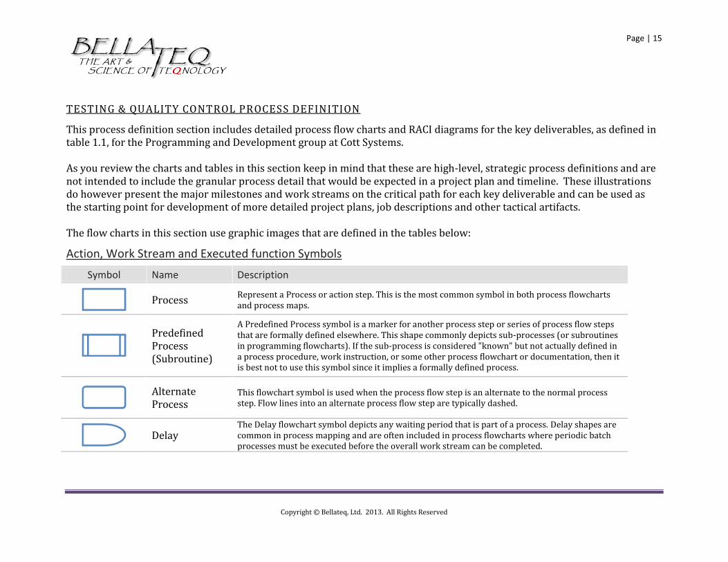
This process definition section includes detailed process flow charts and RACI diagrams for the key deliverables, as defined in table 1.1, for the Programming and Development group at Cott Systems. As you review the charts and tables in this section keep in mind that these are high-level, strategic process definitions and are not intended to include the granular process detail that would be expected in a project plan and timeline. These illustrations do however present the major milestones and work streams on the critical path for each key deliverable and can be used as the starting point for development of more detailed project plans, job descriptions and other tactical artifacts. The flow charts in this section use graphic images that are defined in the tables below:
Action, Work Stream and Executed function Symbols
Symbol Name Description
Process
Represent a Process or action step. This is the most common symbol in both process flowcharts and process maps.
Predefined Process (Subroutine)
A Predefined Process symbol is a marker for another process step or series of process flow steps that are formally defined elsewhere. This shape commonly depicts sub-processes (or subroutines in programming flowcharts). If the sub-process is considered "known" but not actually defined in a process procedure, work instruction, or some other process flowchart or documentation, then it is best not to use this symbol since it implies a formally defined process.
Alternate Process
This flowchart symbol is used when the process flow step is an alternate to the normal process step. Flow lines into an alternate process flow step are typically dashed.
Delay
The Delay flowchart symbol depicts any waiting period that is part of a process. Delay shapes are common in process mapping and are often included in process flowcharts where periodic batch processes must be executed before the overall work stream can be completed.
Copyright © Bellateq, Ltd. 2013. All Rights Reserved
Page | 16
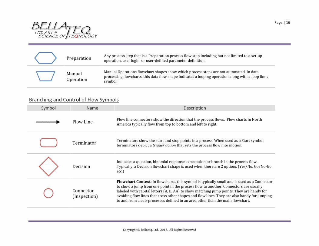
Preparation
Any process step that is a Preparation process flow step including but not limited to a set-up operation, user login, or user-defined parameter definition.
Manual Operation
Manual Operations flowchart shapes show which process steps are not automated. In data processing flowcharts, this data flow shape indicates a looping operation along with a loop limit symbol.
Branching and Control of Flow Symbols
Symbol Name Description
Flow Line Flow line connectors show the direction that the process flows. Flow charts in North America typically flow from top to bottom and left to right.
Terminator
Terminators show the start and stop points in a process. When used as a Start symbol, terminators depict a trigger action that sets the process flow into motion.
Decision Indicates a question, binomial response expectation or branch in the process flow. Typically, a Decision flowchart shape is used when there are 2 options (Yes/No, Go/No-Go, etc.)
Connector (Inspection)
Flowchart Context: In flowcharts, this symbol is typically small and is used as a Connector to show a jump from one point in the process flow to another. Connectors are usually labeled with capital letters (A, B, AA) to show matching jump points. They are handy for avoiding flow lines that cross other shapes and flow lines. They are also handy for jumping to and from a sub-processes defined in an area other than the main flowchart.
Copyright © Bellateq, Ltd. 2013. All Rights Reserved
Page | 17
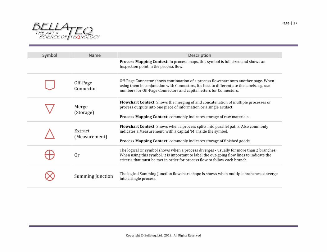
Symbol Name Description Process Mapping Context: In process maps, this symbol is full sized and shows an Inspection point in the process flow.
Off-Page Connector
Off-Page Connector shows continuation of a process flowchart onto another page. When using them in conjunction with Connectors, it's best to differentiate the labels, e.g. use numbers for Off-Page Connectors and capital letters for Connectors.
Merge (Storage)
Flowchart Context: Shows the merging of and concatenation of multiple processes or process outputs into one piece of information or a single artifact. Process Mapping Context: commonly indicates storage of raw materials.
Extract (Measurement)
Flowchart Context: Shows when a process splits into parallel paths. Also commonly indicates a Measurement, with a capital 'M' inside the symbol. Process Mapping Context: commonly indicates storage of finished goods.
Or
The logical Or symbol shows when a process diverges - usually for more than 2 branches. When using this symbol, it is important to label the out-going flow lines to indicate the criteria that must be met in order for process flow to follow each branch.
Summing Junction
The logical Summing Junction flowchart shape is shows when multiple branches converge into a single process.
Copyright © Bellateq, Ltd. 2013. All Rights Reserved
Page | 18
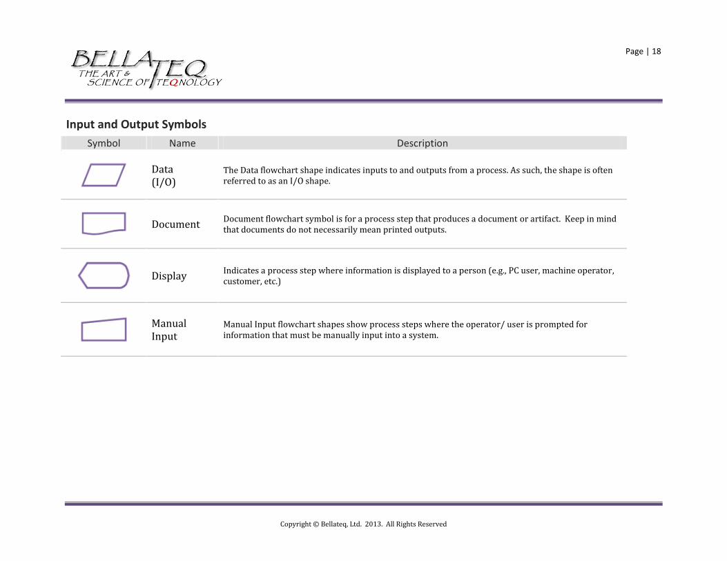
Input and Output Symbols
Symbol Name Description
Data (I/O)
The Data flowchart shape indicates inputs to and outputs from a process. As such, the shape is often referred to as an I/O shape.
Document
Document flowchart symbol is for a process step that produces a document or artifact. Keep in mind that documents do not necessarily mean printed outputs.
Display
Indicates a process step where information is displayed to a person (e.g., PC user, machine operator, customer, etc.)
Manual Input
Manual Input flowchart shapes show process steps where the operator/ user is prompted for information that must be manually input into a system.
Copyright © Bellateq, Ltd. 2013. All Rights Reserved
Page | 19
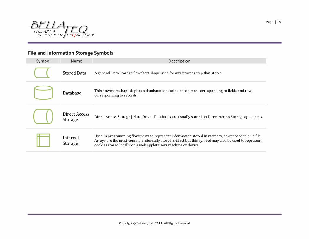
File and Information Storage Symbols
Symbol Name Description
Stored Data A general Data Storage flowchart shape used for any process step that stores.
Database
This flowchart shape depicts a database consisting of columns corresponding to fields and rows corresponding to records.
Direct Access Storage
Direct Access Storage | Hard Drive. Databases are usually stored on Direct Access Storage appliances.
Internal Storage
Used in programming flowcharts to represent information stored in memory, as opposed to on a file. Arrays are the most common internally stored artifact but this symbol may also be used to represent cookies stored locally on a web applet users machine or device.

Copyright © Bellateq, Ltd. 2013. All Rights Reserved
Page | 20
The RACI diagrams in this section use the following coding nomenclature:
SCENARIO POTENTIAL RESOURCE ALLOCATION ISSUE
R – Responsible
Responsible parties own the project, work stream and/or deliverable assigned to them and are ultimately the point person for their quality and on-time delivery. Responsible parties, by definition are Accountable and must sign off on projects, work streams and deliverables before they can be considered complete
A - Accountable
Accountable parties must sign off on (approve) projects, work streams and or deliverables before than can be put into production or made available for external distribution
C – Consulted
Consulted parties have information, own content, have capabilities or are subject matter experts such that their contributions are necessary for successful completion of a project, work flow or deliverable
I – Informed
Informed parties must be notified of the results and/or successful completion of projects and work streams and should be made aware of the availability of key deliverables
Copyright © Bellateq, Ltd. 2013. All Rights Reserved
Page | 21
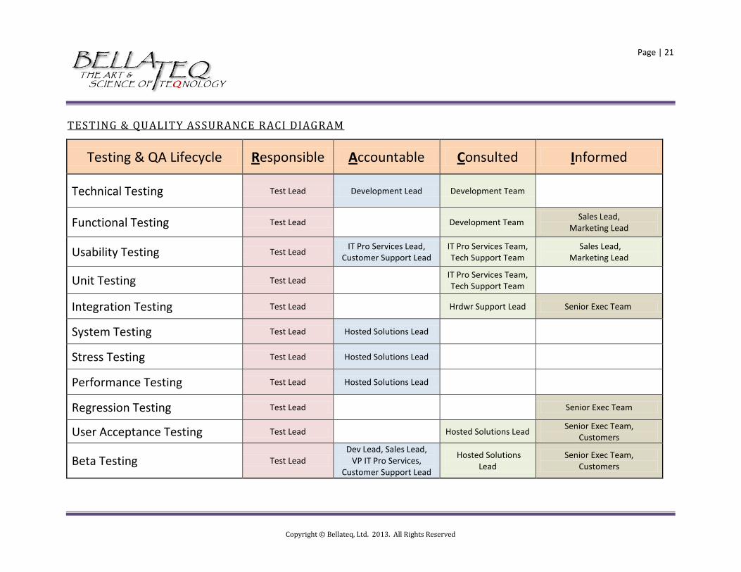
TESTING & QUALITY ASSURANCE RACI DIAGRAM
Testing & QA Lifecycle Responsible Accountable Consulted Informed
Technical Testing Test Lead Development Lead Development Team
Functional Testing Test Lead
Development Team Sales Lead,
Marketing Lead
Usability Testing Test Lead IT Pro Services Lead,
Customer Support Lead IT Pro Services Team, Tech Support Team
Sales Lead, Marketing Lead
Unit Testing Test Lead IT Pro Services Team, Tech Support Team
Integration Testing Test Lead Hrdwr Support Lead Senior Exec Team
System Testing Test Lead Hosted Solutions Lead
Stress Testing Test Lead Hosted Solutions Lead
Performance Testing Test Lead Hosted Solutions Lead
Regression Testing Test Lead Senior Exec Team
User Acceptance Testing Test Lead Hosted Solutions Lead Senior Exec Team,
Customers
Beta Testing Test Lead Dev Lead, Sales Lead,
VP IT Pro Services, Customer Support Lead
Hosted Solutions Lead
Senior Exec Team, Customers

Copyright © Bellateq, Ltd. 2013. All Rights Reserved
Page | 22
APPLICATION BUILD PROCESS FLOW

Copyright © Bellateq, Ltd. 2013. All Rights Reserved
Page | 23