Embed Size (px)
Citation preview

TESTING FIBRE REINFORCED CONCRETE IN AN INVERTED T-BEAM
Matti Lanu
ABSTRACT
Seppo Huovinen Rakenteiden Mekaniikka, Vol. 28 No 3, 1995, s. 25- 43
In this research the main focus is on the analysis of short dispersed steel fibres in a
cement-based matrix. Tests and analyses were performed in order to verify the feasibility
of fibre reinforcement in an inverted T-beam. When considering fibre reinforced concrete
as a load-bearing structural material, the main interest lies on the post-crack tensile
strength of the fibre composite. This post-crack strength gives the ductility, impact
strength and beneficial cracking behaviour. This design and analysis tasks can be solved
with a law-of-mixtures type of approach. This way some simple equation can be
constmcted. Tests are needed to determine the effects of different fibre types and concrete
mix.The calculation methods presented and applied here give a reliable estimation as
compared with test results .
INTRODUCTION
The hollow core slab is the leading product in Finland when it is question of prefabricated
floor slabs. In modern office buildings they are usually supported by steel beams (THQ),
by steel-concrete composite beams or by prestressed concrete beams. To reduce the
stmctural height, the slabs are often placed on the lower flange of the beam in such a way
that the main part of the beam is inside the height of the slab.
One of the prestressed concrete beam types is the so-called "Inverted T-beam", which
describes its form well.
The flange of the invet1ed T-beam has to be reinforced, because the ends of the slabs rest
on the flanges. The aim of the research was to study the possibility to use fibre reinforced
concrete in the flanges, insteact of the conventional reinforcement.
25

TEST STRUCTURES
To verify the design assumptions, the load-carrying capacity of the flange was determined
with tests. The specimens were 1.2 m long simply supported beams. The flange was cut
near the support in order to lead all the stresses to the web of the beam. The load was
distributed to both flanges with steel parts. Di splacements were measured in the middle
span and near supports both on the centre line and on the edge line of the flange. The
dimensions of the test beams and test arrangements are presented in the next fi gure.
' P !
--"--J:
I ~
d~_ ~ '
Dial gauge u
I
p
I
P/2
1 122 ,
DET n -~ ~~ ~ -~~
25j- +-; 15
!
k kl 1 100, 500 1200 1000 j
Fig. 1. Test arrangements
There were five different types of reinforcement in the test beams. One of the beam types
contained normal stirrups . The other four beam types contained only main bars and
varying amounts of fibres. The test for each type was performed on three beams in order to
get information about the deviation of capacity.
26

The test structures were cast in VTT. Prestressing tendons that are used in normal
production were replaced with same number of rebars. After casting the beams were stored
for one day under a plastic film. Demoulding took place on the second or third day and
loading after one week.
The cross-sections of the beams are shown m the next figure, and the amount of
reinforcement in the next table.
2 7

320 150 J 384~
P11 8, 81 6 P11A, t t o
P1 C 1 t- , A2, 4
, I r
300
~ r/ J 26, 209 [ J 82, 8+8 z 2+2 ~,l
36L J + :::;;; : t 4x50 + 6~ - t " A 1' 5+5 = T i l 11
"" ± ± ± ± + --J-50 1 o~o¥ r ± ± ± ± = : ± ± ± 1 ·f 350 ·~
~~5~5~5~ 1ootoC~~o~of go 1r I 8 r I''
P12A, rc150 >k 380~ P128, I
12C
F0,5 83, 2+2 A1, 5+5
~ / J
I r
\-:: ;, ' ± ± ± *,... t '>
~
P13A, F1 ,0 83 , 2+2 A1, 5+5
P138, P13C '-:: ~,, I ~±±~±, t
t '> ' '
t
<t=*** *> t* * **..,
P14A, P148,
P14C
83 , 2+2 A1, 5+5
~+±~±, ~
4x50 J r
+ ± ± ± > 250
1-
4x50 ,lr
± ± ± ± >
250
4x50
± ± ± +,...
~~-25_0~--'1'~
P15A, P158,
P15C
t****,. t±±+*,
F1 ,5
'-:: \, I '> ' '
'
t±*++,... t * *
83, 2+2 A1, 5+5
~ ± ~±
± + >
>
4x50 J t r t ± ± ± ± >
f 250
·~
Fig. 2. Cross-sections of the beams.
28

Table 1. Quantities of materials in the test beams.
Beam symbols P11 A, P11 B, P11 C
Rebars and fibres symbo l stee l q, bar length number of bars bar weight grade mm mm pes. kg
Rebars A1 B500K 12 1200 10 10.6
Rebars A2 B500K 10 1200 8 5.9
Stirrups; web B1 B500K 8 300 + 320 + 300 = 920 6 2.2
Stirrups; flange B2 B500K 8 350 +50+ 350= 750 16 4.7
TOTAL 23.4 kg
Beam symbols P12A, P12B, P12C
Rebars and fibres symbol steel q, bar & fibre length bar & fibre number I bar & fibre grade mm mm quantity pes. I val% weight
kg
Rebars A 1 B500K 12 1200 10 10.6
Rebars B3 B500K 10 250 4 0.6
Fibres; Dramix F0,5 ZP 0.5 50 0.5 7.9
TOTAL 19.1 kg
Beam symbols P13A, P13B, P13C
Rebars and fibres symbo l stee l q, bar & fibre length bar & fibre number/ bar & fibre grade mm mm quantity pes. I val% weight
kg
Rebars A1 B500K 12 1200 10 10.6
Rebars B3 B500K 10 250 4 0.6
Fibres; Dramix F1 ,0 ZP 0.5 50 1.0 15.8
TOTAL 27.0 kg
Beam symbols P14A, P14B, P14C
Rebars and fibres symbo l stee l q, bar length number bar weight grade mm mm of bars pes. kg
Rebars A 1 B500K 12 1200 10 10.6
Rebars B3 B500K 10 250 4 0.6
TOTAL 11.2 kg
Beam symbols P15A, P15B, P15C
Rebars and fibres symbo l stee l $ bar & fibre length bar & fibre number/ bar & fibre grade mm mm quantity pes. I va l% weight
kg
Rebars A1 B500K 12 1200 10 10.6
Rebars B3 B500K 10 250 4 0 .6
Fibres; Dramix F1 ,5 ZP 0.5 50 1.5 23.6
TOTAL 34.8 kg
29

CONCRETE MATERIALS USED IN THE TEST STRUCTURES
The concrete used was normal concrete and the mixture was kept constant while the fibre
content was varied . The mix proportions of the concrete is presented in the next table.
Table 2. Concrete mixes used in the tests .
Mix symbo ls LOO L05 L10 L15
Beam symbols P11,P14 P12 P13 P15
MIX kgfm3 kgfm3 kgfm3 kgfm3
Binding agents
(c) Portland P40/3 390 390 390 390 (s) si li ca 43 43 43 43
Binding agents TOTAL 433 433 433 433
Aggregate
filler < 0,125 133 131 131 131
0,1-0,6 mm 266 263 263 262
0,5-1,2 mm 266 263 263 262
1-2 mm 266 263 263 262
2-3 mm 398 394 394 393 3-5 mm 398 394 394 393
5-10 mm 159 158 158 157 (a) Aggregate TOTAL 1886 1866 1866 1860
(w) Water 132 140 140 139
Water cement ratio (w + 0 .6add)/(c + s) 0.34 0 .35 0 .35 0 .36
Aggregate cement ratio a/(c+s) 4.39 4.31 4.31 4.30
Admixtures
(add) Scancem SP 62 22 22 22 25
Steel fibres
Dramix ZC 50/.50 39 78 117 vol.% 0.5 1.0 1.5
TOTAL kgfm3 2473 2500 2539 2574
Basic properties of the fresh concrete were determined only with concrete without fibres
and with a fibre content of 0.5 per cent by volume. Mechanical properties were determined
either with casted prisms or with drilled cylinders from loaded structures. The results are
shown in the next table.
30

Table 3. Properties of concrete used in tests.
Mix symbo ls LOO L05 L 10 L15
Beam symbols P11, P14 P12 P13 P15
METHOD PROPERTIES Symbol
SFS 5284 I Slump test mm 19 23
SFS 5287 2 Air content % 3.8 9.0 - -
SFS 5288 3 Density kg fm3 2406 2307 - -
ASTM Flexural strength MPa .frcb u 6.68 5.66 9.36 14.84 C1018 - 92 prisms 1 OOx 1 00x500
average of 3 results (2 results)
First crack MPa .frcbcr - 4 .99 6.68 8 .2
Toughness index Is 3.97 4.22 4.99
/10 7.43 8.73 10.88
120 15.05 16.63 24.98
SFS 4474 4 Compressive strength MPa frccu 91.2 65.6 72 .8 101. 2 cp= 75 mm, h = 75 mm
average of 6 results
SFS 5443 5 Tensile sp litting strength MPa .frcsp 5.13 4 .52 6.63 9.57 ~= 100 mm, h = 100 mm
average of 6 results
SFS 5445 Tensile strength MPa .frctu 4.8 3.9 3 .7 4.6 ~ = 75 mm, h = 75 mm
average of 6 results
If we calculate the ratio between direct tensile strength./fctu and flexural strength./{cbu, we
obtain the following values:
LOS , (fibre content 0.5%): /jehu= 1.45/jctu
LlO, (fibre content 1.0%): /jehu= 2.53/jctu
Ll5 , (fibre content 1.5%): /jehu= 3.23/jctu
The values above indicate that a fibre content of 0.5 per cent by vo lume does not give
much ductility. It can be confirmed by structural test results. Also it is clear that direct
tensile strength is underestimated due to the difficult test arrangements. The values agree
rather well with the range of theoretical values.
1 Based on the international standard ISO 4109 2 Based on the international standard ISO 4848 3 Based on the international standard ISO 6276 4 Based on the international standard ISO 40I2 5 Based on the international standard ISO 4 I 08
31

The material properties are summarized in the next two figures.
16
t 14 .
12 - • - flexural strength
10 .
l • ---o- flexura I era eking I strength
Strength 8 ~
MPa • - • - tensile sp litting
6 ' ' ~
strength
:L_ ' ~ ! ---<>- te n sile strength
0 .00% 0.50% 1.00% 1.50%
Fibre volume fra etio n
Fig. 3. Determined strength values as a function of the fibre content; the minimum, maximum and average values are presented.
30
25 ! •
20
I -•- lndexl5
Index 15 i ---o- Index 110
value ! ---+- Inde x 120
10 bl
8 g 5
I I I
0
0.00% 0.50% 1.00% 1.50%
Fibre volume fra etio n
Fig. 4. Toughness index values (Is, I 10, I2o) as a function of the fibre content; the minimum, maximum and average values are presented.
32
TEST RESULTS AND ANALYSIS
Load-deflection curves are presented in the next five figures.
250 +--------+--------~------~--------~--------~-----
kN
-=- P11B
50 --- P11C
0 0.5 1.5 2 2.5
mm
Fig. 5. Average deflections of flange; beam PllA ... C with normal stirrups.
250
P12A -200
-=- P12B
150 P12C
-
kN '-------- ·
100
50 ! ... ~
0
0 0.5 1.5 2 2.5
mm
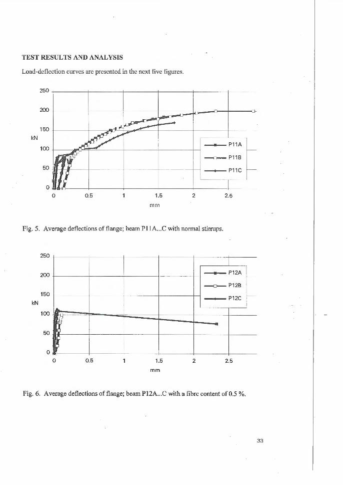
Fig. 6. Average deflections of flange; beam P12A ... C with a fibre content of0.5 %.
33

250
200
kN
......--!..-
:~~ P13A 1-
-=:,---- P13B
.u 1-
P13C
150
100
50
0
0 0.5 1.5 2 2.5
mm
Fig. 7. Average deflections of flange; beam Pl3A .. . C with a fibre content of I%.
250
200
150 P14A r----kN
' -=- P14B
r---100
P14C
50
0
0 0.5 1.5 2 2.5
mm
Fig. 8. Average deflections of flange ; beam Pl4A ... C with main bars only.
34

250
kN
200 ~ ~ , P15A -, -=- P15B
c-~ P15C
150
100
50
0
0 0.5 1.5 2 2.5
mm
Fig. 9. Average deflections of flange; beam P15A ... C with a fibre content of 1.5 %.
A summary of the beam test results is presented in the next figure as a function of the total
amount ofreinforcement steel (rebars and fibres) in the test structure.
250 . 200
150 Load
kN 100
P15 ~ 1-o-cracking load 1 - 1.5vol%
[-+- ultimate load [ pt - t-
! E reba rs
~13 I I - P14 P12 B 1.0vol%
Oval% 0.5 vol%
50
0 I 10 15 20 25 30 35
Amount of steel kg
Fig. 10. Beam test results as a function of the total amount of reinforcement steel.
A flange with normal shear reinforcement collapses when the reinforcement yields or if
the anchorage of the stirrups is insufficient. If fibre reinforcement is used, the tensile
strength of the concrete is critical. The dimensioning of the flange in the ultimate state can
35

be made according to the cases illustrated in the next figure. The cracking load IS
calculated by assuming the linear elastic stress distribution.
The cracking load P cr and the ultimate load Pu of a normally reinforced flange is
calculated using the following equations:
1 -Per 2
(1)
(2)
The following equations are used in the case of fibre reinforced concrete. The cracking
load P cr is estimated with the equation:
(3)
The ultimate capacity Pu of a fibre reinforced flange is estimated with next two equations.
The first one can be used when the height of the compression zone is 0.25 times the total
height and the compressive stresses are in the elastic range. This is used, for example, by
Hannant /3/:
(4)
The second alternative is the case where both the compression and the tensile zone are
modelled with rectangular stress blocks; this is suggested, for instance, by Lim et al. /4/:
'J Note that often fctu > fJctu ~A Vj- fc
df
(5)
The ultimate bending capacity Pu can be estimated using the flexural strength ./fcbu with
the equation /6/, /J /:
36
f _ { fJcbcrRS.IO
fcbu -· fjcbcrRI 0.20
(6)
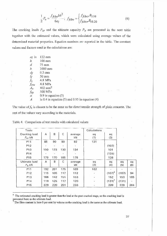
The cracking loads P cr and the ultimate capacity P 11 are presented in the next table
together with the estimated values, which were calculated using average values of the
determined material properties . Equation numbers are rep011ed in the table. The constant
values and factors used in the calculations are:
0/ IS 122 111111
h 100 111111
d 75 nun b 1000 mm d; 0. 5 111!11
l_r 50 mm f 1 4.8 MPa f ctu 4.8 MPa As 402 mm2
hy 500 MPa a 0.9 in equation (5) A is 0.4 in equation (5) and 0.95 in equation (4)
The value ofj1 is chosen to be the same as the direct tensile strength of plain concrete. The
rest of the values vary according to the materials.
Table 4. Comparison of test results with calculated values
Tests Calculations
Cracking load A
I B
I c average eq eq
Per kN kN ( 1) (3)
P11 85 80 80 82 131 P12 - - - - (107) P13 150 123 130 134 101 P14 - - - ( 131) P15 179 170 185 178 126
Ultimate load A
I B I c average eq eq eq eq P11 kN kN (2) (4) (5)
P11 192 201 175 189 162 - -
P12 115 105 117 112 - (1 07)6 (107) P13 166 142 151 153 - 152 153 P14 119 125 117 120 - ( 131) 7 (131) P15 229 220 251 233 - 228 229
6 The estimated cracking load is greater than the load at the post cracked stage, so the cracking load is presented here as the ultimate load. 7 The fibre content is here 0 per cent by volume so the cracking load is the same as the ultimate load.
(6)
-
94 165
-264
37

It can be stated that both equations (4) and (5) give equal results . However, it can be
concluded that equation (5) is more suitable for this case.
As mentioned earlier, factor A has different values in these two equations. In theory factor
A should be in the range of 0.08 to 0.5 in this type of application. This is because factor A
depends on both the fibre orientation factor 11~ and the fibre bond efficiency factor 'Ill and
they both are far below 1.0. The values for these factors in a random 3-dimensional case
are listed below /2//3/:
1 1 11 ~ = 6"' 2 (7)
1 lf 1 lf when lj<< lcril , then- - - < 111 < - --
4 lcril 2 lcrit
where l · - dJfJu C/'1/ - 2ft
(8)
The following equation can be written to express the tensile strength fjctu in the cracked
stage.
(9)
Values for fjctu are repmted in Table 5. The values are compared with the modulus-of
mpture values obtained from the test results according to the following expression:
(10)
38

Table 5. Tensile strength of fibre reinforced concrete ./jctu ( eq (9)) used in previous calculations and comparison with modulus-of-rupture values.!jcbu (eq (10)).
Fibre content 0 .5% 1.0% 1.5%
Beam symbo ls P12 P13 P15
from test results ./jcbu MPa (4.1 0) 8 5 .60 8 .53
in eq (4) ./jctu MPa 2.28 4 .5 6 6.84 A=0 .95
./jc b u/fjc lu (1.80) 1.23 1.25
in eq (5) A= 0.4 ./jctu MPa 0.96 1.92 2.88
./jcbu/fjctu (4.27) 2.92 2.96
The ratio ./jcbu/fjctu should be about 1.5 in plain concrete !51 and its theoretical maximum is
3.0. Bentur & Mindess /2/ suggest the value 2.44. So the latter equation (5) represents well
the situation at the ultimate state with fibre contents of 1% and 1.5%.
From test the results it can be seen that a fibre content of 0.5% is too low to act as a
structural reinforcement. This can be verified by calculating the theoretical critical fibre
volume in bending with the following equations /2/, /3/:
r; lension = (2 12) fctu d f ~ 20/ 12o/ ,. crt/ . . . . / O.... / O
ft lf vbeJJding ~ 0 41 ' v_lension = 0 820/ 4 920/
en/ · en/ · /O. · · · · /O
(11)
(12)
In this case the value 0.82 % is obtained as the lowest estimate. So it is clear that to have
any structural meaning, the fibre content should be near I per cent by volume. If the mix
proportion of this composite is adjusted, this value will also be changed. On the other
hand, the casting became more arduous when the fibre content was increased from 1 % to
1.5 % by volume. This problem can be easily solved by changing the mix proportion.
However, this was not under consideration here.
8Here the maximum load is the cracking load, because the fibre content is below the critical fibre volume
fraction. So comparing this value with this assumed post-crack tensile strength is not reasonable.
39

CONCLUSION
The fibres increase the fracture load obtained in the tests compared with the load of a
flange without reinforcement. With fibre content more than one volume per cent, it is
possible to have a higher fi·acture load than with a normal reinforcement similar to that in
the existing beam type. The fi·acture load can be predicted with simple equations.
With a fibre content of 1.0 volume%, the test structures have visible toughness. It can be
assumed that this fibre content exceeds the critical value.
To study the feasibility of fibre-reinforcement, also the toughness and deformation
capacity have to be taken into consideration. The role of the flange can be described with
following notes:
The flange is used to support the hollow core slabs. It carries all the
loads in the assembly phase, before the slabs are grouted. After that, a
certain percentage of the load is transferred to the beam web with
dowel action. However, this is not taken into consideration, because
there are no practical methods of estimating this .
The flange is designed only against the flexural load and horizontal
load from friction when the slabs are deformed. The amount of
reinforcement is small and the flange collapses when the
reinforcement yields.
No analysis for studying the deformations of the flange is carried out.
The ductility is assumed to be achieved by using conventional
reinforcement.
There are no requirements for deformation capacity in this pm1icular
application. Though it can be said, that the larger the deformations
the better.
Fibres are a complicated type of reinforcement although they make the manufacturing
easy. The following observations can be made:
40

Fibres are situated and oriented randomly in the concrete. Although
the test results show only minor deviations, there is still a risk of a
poor fibre dispersion.
Steel fibres are practically always pulled out of concrete, so the
fracture occurs due to the poor anchorage of the fibres . Insufficient
anchorage is traditionally categorized as a brittle mode of fracture.
The deflections of flanges become smaller when the fibre content is
increased. However, this is not a sign of a poor ductility. It is
commonly accepted, that fibres increase the stiffness of a concrete
structure at the cracked stage and as a consequence the deflections are
smaller.
As a conclusion it can be said that fibres can be used when the following details are
solved:
The fibre content has to be sufficiently high, so that the fibre content
exceeds the critical fibre volume-value. The correct fibre content can
be ensured by performing a flexural toughness test, for example
according to ASTM C 1018.
Quality control has to be planned m order to maintain constant
surveillance of the actual propetties of the fibre-reinforced concrete.
Safety levels have to be studied carefully. A suggestion for a material
safety coefficient lies between the values of unreinforced and
normally reinforced concrete.
The question of economics is more complicated. In terms of the reinforcing material
needed per cubic meter we can say that in the form of dispersed fibres there has to be 30%
more steel than in the form of conventional steel bars. When comparisons were made in
co-operation with the manufacturer of the original beam type, it was found that about one
per cent by volume is the maximum if the normal reinforcement is done with welded steel
mesh. When using separate steel bars this value can be little higher.
41

ACKNOWLEDGEMENTS
The research presented here was done in a project carried out at the Teclmical Research
Centre of F inland (VTT) with financial support of the Technology Development Centre
(TEKES). The research was led by Prof. Asko Smja. The planning and execution of the
studies were co-ordinated by a steering group: Mr Kauko Linna from Lohja Oy Ab
(convenor), Olli Korander from Partek Betonila Oy Ab, Mr. Olli -Pekka Nordlund from
TEKES and Dr. Seppo Huovinen from Helsinki University ofTechnology.
Tests with materials as well as the manufacture of test structures took place in the VTT
Building Teclmology under the guidance of Mr. Kai Tattari and Mr. Heikki Ii sakkila.
Structural tests were carried out by Mr. Heikki Lintunen and Mr. Mats Rundt. Studies
concerning the economics of fibre reinforcement were carried out by Mr Olli Korander,
Mr. Pekka Hayrinen and Mr. Antti Koponen from Partek Betonila Oy Ab.
LIST OF SYMBOLS
11¢
11/ a, A a, As
b
d
elf
ft fctu
ficbcr
fichu
!jeer fjccu
ficsp
ficw .fji, fsy h
Is !10 l2o
lcril
42
Orientation efficiency factor of fibres
Bond effi ciency factor of fibres
Factors
Loading span
Cross-sectional area of reinforcement steel
Width of a cross-section
Effective height of reinforced concrete structure
Fibre diameter
Bond strength between fibres and matrix
Ultimate tensil e strength of plain concrete
Flexural first-crack strength of fibre reinforced concrete
Ultimate fl exural strength of fibre reinforced concrete
Cracking strength of fibre reinforced concrete
Ultimate compressive strength of fibre reinforced concrete
Splitting tensile strength of fibre reinforced concrete
Ultimate tensile strength of fibre reinforced concrete
Ultimate tensile strength of fibres
Yielding strength of stee l
Height of a cross-section
ASTM toughness index
Critical fibre length

fr Fibre length
P cr Cracking load
P11 Ultimate load
RN.M ASTM residual strength factor
Vcrit Critical fibre volume fraction
VI Fibre volume fraction
REFERENCES
1. ASTM C 1018 - 92. Standard test method for flexural toughness and first-crack strength of fiber-reinforced concrete (using beam with third-point loading).
2. Bentur, A. & Mindess, S. Fibre reinforced cementitious composites. London 1990, Elsevier. 449 p.
3. Hannant, D . J., Fibre cements and fibre concretes, John Wiley & Sons, Chichester, 1978,2 19 pp
4. Lim, T., Paramsivam, P., Lee, S. Bending behaviour of steel-fiber concrete beams. ACI Structural Joumal 84(1987)6 pp 524-536
5. Neville, A. M. Properties of concrete. Pitman, Great Britain 1983
6. Westin, 1. , Peterson, b., Nordin, A., Sta!fiberarmerade industrigolv . Stockholm 1992, Cement och Betong institutet, CBI Rapport 6:92, 55 pp
Matti Lanu M.Sc.(Tech.), Research Scientist VTT Building Technology Kivimiehentie 4, Espoo, P. 0 . Box 1803, FIN-02044 VTT, Finland Tel +358 0 4561 Fax +358 0 456 4815
Seppo Huovinen Ass.prof., Dr. Tech. Helsinki University of Technology Rakentajanaukio 4 FIN-02150 ESPOO, Finland Tel +358 0 451 3718 Fax +358 0 451 3724
43