Embed Size (px)
Citation preview

Testing and analyzing methods for truncated binary
multiplication.
Andreas Thor Winther - S053010
Finishing Bachelor Project
Spring 2009

Testing and analyzing methods for truncated binary
multiplication.
Report made by:
Andreas Thor Winther - s053010
Supervisor:
Associate Professor Alberto Nannarelli
DTU Informatics
Institute of Informatics and Mathematical Modeling
Technical University of Denmark
Richard Petersens Plads
Bygning 322
2800 Kgs. Lyngby
Danmark
Released: June 27. - 2009
Edition: 1.Edition
Notes: This report is written as documentation of a B.Eng. project made at
Informatics and Mathematical Modeling at the Technical
University of Denmark.

Andreas T. Winther June 2009 Testing and analyzing of several methods for truncated multiplication in binary
i Abstract
Multiplication operations are frequently required in digital signal processing. To increase
the speed with which these are done, parallel multipliers can be used. These however
require a large area on the chip and consume much power. An important goal would
therefore be to reduce the area requirements. The purpose of this project is to analyze
several methods of performing truncated multiplication and to determine which method
would be most efficient for unsigned numbers of 8, 16 or 32 bits.
Truncated multiplication is a technique where only the most significant columns of the
multiplication matrix are used and therefore area requirements can be reduced by up to
46.08 % for 32 bit inputs. This however leads to a rounding error and a reduction error
which needs to be corrected by introducing a correction constant, and the goal of this
project is to determine the point of balance for error vs. hardware savings. The scope of
this project is to evaluate different well-known area reduction methods along with
minimizing the error.
The multiplier is implemented using VHDL (VHSIC Hardware Description Language,
where VHSIC stands for Very High Speed Integrated Circuit) and simulated with
ModelSim/Xilinx ISE in order to observe the hardware area reduction. It is also
implemented and simulated using Matlab’s Simulink tool in order to evaluate the error.

Andreas T. Winther June 2009 Testing and analyzing of several methods for truncated multiplication in binary
ii Resumé
Ved digital signal behandling stilles der ofte krav om multiplikation. For at øge
hastigheden af denne proces kan parallelle multiplikatorer finde anvendelse, men dette
optager stor plads på chip’en og kræver desuden en betydelig effekt. Det er derfor af
vigtighed at reducere kravet til plads (og dermed effekt) gennem brug af forskellige
metoder til udførelse af trunkeret multiplikation og til at bestemme hvilken metode, der er
den mest effektive for ikke-fortegnsbestemte tal på 8, 16 eller 32 bits.
Trunkeret multiplikation er en teknik, der kun bruger de mest betydningsfulde søjler i
multipliktionsmatricen for bl.a. at spare plads. Teknikken fører imidlertid til
afrundingsfejl og reduktionsfejl, som der derfor må korrigeres for gennem inddragelse af
en korrektionskonstant.
Formålet med dette projekt er at bestemme balancepunktet mellem præcisionsfejl og
plads på hardwaren. Projektets mål er at evaluere forskellige allerede kendte metoder, der
sigter mod pladsbesparelse samtidig med en minimering af fejlforøgelsen.
Multiplikatoren implementeres gennem brug af VHDL (Very High Speed Integrated
Circuit Hardware Description Language), og simuleres med modelSim/Xilinx ISE med
det formål at konstatere pladsbesparelsen i hardwaren. Ved at bruge Matlab’s redskab
Simulink implementeres og simuleres den endvidere med det formål at observere
fejlforøgelsen.

Andreas T. Winther June 2009 Testing and analyzing of several methods for truncated multiplication in binary
iii Preface
This report is written as documentation of a B.Eng. project made at the Informatics and
Mathematical Modeling department of the Technical University of Denmark.
The team consisted of Andreas Thor Winther. The project supervisor at DTU was
Associate Professor Alberto Nannarelli. Amanuensis Edward Alexandru Todirica helped
with the technical part of the VHDL implementation.
The project was about reducing area consumption on conventional parallel multipliers
using truncation. The report consists of an analysis of the problem, a description of a
possible solution, and a presentation of how it might be designed and implemented.
Lyngby, June 2009
Andreas Thor Winther

Andreas T. Winther June 2009 Testing and analyzing of several methods for truncated multiplication in binary
iv Acknowledgements
The project was proposed by Associate Professor Alberto Nannarelli of IMM1 who also
made sure I got a desk, along with the needed hardware and software, to carry out the
task. I would like to thank Alberto for giving me the opportunity to work on this project
and for being available during the project period.
I would also like to thank Amanuensis Edward Alexandru Todirica for helping me with
various problems concerning both VHDL problems and the writing of the report.
Furtermore I would like to thank Emil N. Jakobsen, Markku Eerola, Bjarne Petersen and
Troels Winther for reading through the report and for coming with constructive criticism.
1 IMM: Informatics and Mathematical Modelling at the Technical University of Denmark

Table of Contents
i Abstract ........................................................................................................................
ii Resumé.........................................................................................................................
iii Preface..........................................................................................................................
iv Acknowledgements......................................................................................................
1 Introduction................................................................................................................. 1
1.1 The problem........................................................................................................ 1
1.1.1 Problem description .................................................................................... 1
1.1.2 Motivation................................................................................................... 2
1.2 The project .......................................................................................................... 2
1.2.1 Structure of the report ................................................................................. 2
1.2.2 List of terminologies ................................................................................... 3
1.2.3 Tools used ................................................................................................... 5
1.2.3.1 Matlab r2008b – Simulink ......................................................................5
1.2.3.2 ModelSim 6.3a........................................................................................ 5
1.2.3.3 Xilinx ISE 9.2i ........................................................................................ 5
1.2.4 Hardware used ............................................................................................ 6
1.2.5 Method ........................................................................................................ 6
2 Theoretical background .............................................................................................. 8
2.1 Binary multiplication .......................................................................................... 8
2.1.1 Rounding..................................................................................................... 9
2.1.2 Truncation ................................................................................................. 10
2.2 Conventional multipliers................................................................................... 11
2.3 Binary addition.................................................................................................. 11
2.4 Carry-save adder (CSA) multiplier................................................................... 15
2.4.1 Multiplier trees.......................................................................................... 16
3 Analysis..................................................................................................................... 18
3.1 Priorities............................................................................................................ 18
3.2 Problem solving ................................................................................................ 18
4 Design ....................................................................................................................... 20
4.1 Matlab – Simulink model.................................................................................. 20

Andreas T. Winther June 2009 Testing and analyzing of several methods for truncated multiplication in binary
4.2 Modelsim – VHDL model ................................................................................ 21
5 Implementation ......................................................................................................... 23
5.1 Matlab – Simulink............................................................................................. 24
5.2 VHDL ............................................................................................................... 26
5.2.1 Components.vhd ....................................................................................... 27
5.2.1.1 Fadd – 1-bit Full adder.......................................................................... 27
5.2.1.2 CLA_g – n-bit Carry look-ahead adder ................................................ 28
5.2.1.3 CSA_g – Carry-save adder ................................................................... 29
5.2.2 Nxn_mult.vhd ........................................................................................... 30
5.2.3 Testbench.vhd ........................................................................................... 30
5.3 Testing............................................................................................................... 31
5.3.1 Matlab – Simulink test .............................................................................. 31
5.3.2 Modelsim – Xilinx ISE simulation ........................................................... 31
5.3.3 Testing on an FPGA.................................................................................. 32
6 Results....................................................................................................................... 33
6.1.1 Precision error........................................................................................... 33
6.1.2 Hardware savings...................................................................................... 36
7 Discussion................................................................................................................. 37
7.1 Results evaluation ............................................................................................. 37
7.1.1 Precision Error .......................................................................................... 37
7.1.2 Hardware savings...................................................................................... 39
7.2 Simulink............................................................................................................ 40
7.3 Perspectives....................................................................................................... 41
7.4 Future work....................................................................................................... 41
8 Conclusion ................................................................................................................ 42
9 References................................................................................................................. 44
10 Appendix A – Matlab Simulink Design.................................................................... 46
10.1 The inside of the Simulink sub-systems ...........................................................46
10.2 Matlab embedded function full source code..................................................... 47
11 Appendix B - VHDL code ........................................................................................ 49
11.1 Nxn_mult.vhd ................................................................................................... 49

Andreas T. Winther June 2009 Testing and analyzing of several methods for truncated multiplication in binary
11.2 Components.vhd ............................................................................................... 51
11.3 Testbench.vhd ................................................................................................... 54
12 Appendix C – Test results......................................................................................... 59
12.1 Simulink test bench........................................................................................... 59
12.2 Simulation diagrams from modelSim ............................................................... 61
13 Appendix D – Synthesis reports ............................................................................... 67
13.1 CLA_g (Carry Look-ahead) VS add_g (Ripple-carry) ..................................... 67
13.2 32-bit input (left = 31)....................................................................................... 67
13.3 16-bit input (left = 15)....................................................................................... 70
13.4 8-bit input (left = 7)........................................................................................... 73
13.5 Example of a full syntesis report ...................................................................... 75

Andreas T. Winther June 2009 Testing and analyzing of several methods for truncated multiplication in binary
Table of figures and tables
Figure 1: 4x4 bit Binary Multiplication. ............................................................................. 9
Figure 2: 4x4 bit Binary Multiplication with truncation degree T=3 ............................... 10
Figure 3: Left: A sequential multiplier, right: A parallel multiplier .................................11
Figure 4: 1-bit full adder with truth table. [10]................................................................. 12
Figure 5: 4-bit Ripple-Carry Adder .................................................................................. 12
Figure 6: 4-bit Carry look-ahead adder. [10] .................................................................... 13
Figure 7: the Full adder and the CSA has same IO. [8] .................................................... 14
Figure 8: CSA array .......................................................................................................... 14
Figure 9: Schematic of the CSA. ...................................................................................... 15
Figure 10: Carry-save adder (CSA) multiplier. ................................................................ 16
Figure 11: Example of a carry-save adder Wallace tree multiplier. ................................. 17
Figure 12: Bit shifting....................................................................................................... 20
Figure 13: The designed Simulink model. ........................................................................ 21
Figure 14: High-level design of the nxn bit parallel CSA multiplier implemented.......... 21
Figure 15: The 2n-bit product. .......................................................................................... 23
Figure 16: Flow diagram of the Embedded Matlab function, multiplier with truncation. 25
Figure 17: Top-View of the VHDL implementation ........................................................27
Figure 18: 2n bit final product of the multiplier ............................................................... 28
Figure 19: The rounding sub-system ................................................................................ 46
Figure 20: The Random Number Generator sub-system .................................................. 46
Figure 21: The Average Calc sub-system......................................................................... 46
Figure 23: left = 3, T = 3. Binary representation .............................................................. 61
Figure 24: left = 3, T = 3. Unsigned representation.......................................................... 62
Figure 25: Left = 31, T = 0 - 28. Binary representation.................................................... 63
Figure 26: Left = 31, T = 0 - 28. Unsigned representation ............................................... 64
Figure 27: left = 3, T = 0 - 3. Binary representation ......................................................... 65
Figure 28: left = 3, T = 0 - 3. Unsigned representation .................................................... 66
Table 1: Precision error for various truncated multipliers ................................................ 35
Table 2: Hardware savings for various truncated multipliers...........................................36

Andreas T. Winther June 2009 Testing and analyzing of several methods for truncated multiplication in binary
Table 3: Maximum precision error for various multipliers ..............................................38
Table 4: Hardware savings compared with [17] ............................................................... 39
Andreas T. Winther June 2009 Testing and analyzing of several methods for truncated multiplication in binary
Page 1 of 94
1 Introduction
This chapter gives an introduction to the problem, the tools used, the methods, and the
structure of the report and the chapter consists of 2 sub-chapters:
1. The problem – an introduction to the problem and what to be done
2. The project – Tools and hardware, methods and the structure of the report.
1.1 The problem
1.1.1 Problem description
Truncation is a well-known method to reduce the hardware area of multipliers. By
applying truncation significant hardware savings can be achieved at the cost of precision.
The problem to be solved in this project is to analyze several methods and degrees of
performing truncated multiplication and to determine which method/degree would be
most efficient for 8, 16, and 32 bits.
There are three main objectives:
1. To determine the error for several methods and degrees of truncation for 8, 16 and
32 bits. This is done in chapter 6
2. To design and implement the parallel multiplier in order to observe the reduction
in area and to confirm if the method works. This is done in chapter 5 and 6
3. To compare the results and determine which area/error balance would be most
efficient for 8, 16 and 32 bits.

Andreas T. Winther June 2009 Testing and analyzing of several methods for truncated multiplication in binary
Page 2 of 94
1.1.2 Motivation
Truncation is a method used to reduce hardware requirements of multipliers, while
remaining very simple in terms of implementation and options to correct for potential
adverse effects. This implies that the results of the project could potentially lead to major
improvements in the design and manufacture of multiplier circuitry. It has been possible
to simulate the effects of truncation, given a wide variety of conditions, without imposing
demands that are impossible to meet using readily available technology. The balance of
challenge and tractability of the stated problem has been a determining factor in the
decision to undertake the project, along with a sense of personal interest and enthusiasm.
Examples of use: [1], [2], [3], [4] , [5].
1.2 The project
In this sub-chapter the structure of the report is presented. Furthermore tools and
hardware used in the project are described. Finally the used methods are briefly
explained.
1.2.1 Structure of the report
The thesis is structured as follows:
Chapter 1 is an introduction to the problem at hand and the tools and methods used.
Chapter 2 gives the theoretical background.
Chapter 3 provides a closer analysis of the problem
Chapter 4 gives a top-view design of the two model implementations
Chapter 5 explains in closer detail the implementation of the two models.
Chapter 6 provides the results of the work.
Chapter 7 discusses the work
Chapter 8 concludes the report
Chapter 9 has a list of used references.
Appendix A unrolls the Simulink model including the full Matlab function source code.

Andreas T. Winther June 2009 Testing and analyzing of several methods for truncated multiplication in binary
Page 3 of 94
Appendix B gives the full source code for the VHDL implementation.
Appendix C provides test results.
Appendix D holds the various synthesis reports used in this report.
1.2.2 List of terminologies
ASIC: (Application-Specific Integrated Circuit), is a chip designed for a
particular application and is pre-programmed
FPGA: (Field Programmable Gate Array) can be reprogrammed and therefore
makes it an excellent choice when testing models
HDL: (Hardware Description Language) – General term for a language used
to describe hardware.
LED: (Light-Emitting Diode): a semiconductor that gives out light when an
electric current is applied to it.
LUT: (Look-Up Table): A data structure, usually an array or associative
array, often used to replace a runtime computation with a simpler array
indexing operation.
MSB: (Most Significant Bit) The left-most bit in a binary represented:
10011000.
RTL: (Register Transfer Level) A way of describing the operation of a
synchronous digital circuit. In RTL design, a circuit's behavior is
defined in terms of the flow of signals (or transfer of data) between
hardware registers, and the logical operations performed on those
signals.
Andreas T. Winther June 2009 Testing and analyzing of several methods for truncated multiplication in binary
Page 4 of 94
Synthesize: See XST.
SystemC: A hardware description language based on C++. [6]
SystemVerilog: A hardware description language based on Verilog. [7]
Verilog: A hardware description language similar to VHDL.
VHDL: (Very High Speed Integrated Circuit Hardware Description
Language) is the VHSIC Hardware Description Language. VHSIC is
an abbreviation for Very High Speed Integrated Circuit.
XST: (Xilinx Synthesis Tool) A Xilinx tool that synthesizes HDL designs.

Andreas T. Winther June 2009 Testing and analyzing of several methods for truncated multiplication in binary
Page 5 of 94
1.2.3 Tools used
Three primary tools were used and below a short introduction is given.
1.2.3.1 Matlab r2008b – Simulink
Matlab is a very powerful mathematical tool which serves many purposes including
manipulation of equations, numbers and models. It is a programming language taking use
of such things as scripts, functions and plug-ins etc. These features combined give an
extremely wide span of mathematical possibilities.
Simulink is a graphical block diagramming tool in Matlab, which is used to draw models
by dragging and dropping building blocks into the model. A wide list of pre-made blocks
is available but also custom user-made blocks can be designed and used. An example
would be a block representing a constant source, a multiplier or a display that shows the
value of the device/block under measurement.2
1.2.3.2 ModelSim 6.3a
ModelSim provides a comprehensive simulation and debug environment for complex
ASIC and FPGA designs. Hardware Description Languages (HDL) like VHDL and
Verilog are typically used. SystemVerilog and SystemC are also commonly used.3
1.2.3.3 Xilinx ISE 9.2i
Xilinx ISE has many uses but in this project it is used to synthesize models made in
ModelSim. It simulates exactly how a model works on a specific device and gives very
detailed analytical information, such as timings, RTL schematics and hardware utilization
on the device4
2 See more about Matlab and Simulink at: http://www.mathworks.com/products/ (14-06/2009) 3 See more about ModelSim at: http://www.model.com/ (14-06/2009) 4 See more about Xilinx at: http://www.xilinx.com/tools/designtools.htm (14-06/2009)

Andreas T. Winther June 2009 Testing and analyzing of several methods for truncated multiplication in binary
Page 6 of 94
1.2.4 Hardware used
The board used in this project was an FPGA of the Spartan 2 family
(more details in the box to the right).
Most FPGA’s meet the requirements needed for this project so the most
readily available board was used.
Furthermore an extension to the board has been used. This extension has
a few buttons and a LED display, and this will be used in the end if the model synthesized
in Xilinx ISE is uploaded to the FPGA for final testing.
1.2.5 Method
Following is a short explanation of how the before mentioned tools were used in this
project.
Matlab was used to simulate the error using Simulink. Two uniformly random numbers
were generated. These numbers were then multiplied using both the built-in (no
truncation, no error) multiplier block and a custom-made Embedded Matlab Function
block with implemented truncation. The truncated product was rounded down to match
the input size of the multiplier and the multiplicand and a correction constant was added
to reduce the error. Lastly the truncated product was subtracted from the real product to
see the deviation (the error resulting from the truncation). Finally the average deviation
from a 1,000,000 samples were calculated and noted.
ModelSim was used to compile the VHDL code and to simulate it.
To see in more detail how the multiplier was implemented, see chapter 0
Spartan 2 board XC2S200 PQ208AMS0229 D1226889A 5C
3 VHDL files were written: • nxn_mult.vhd – The main file with the code needed for the multiplier. • components.vhd – Some components needed (full adder, n-bit adder etc). • testbench.vhd – Testbench used to stimulate inputs to the multiplier
Andreas T. Winther June 2009 Testing and analyzing of several methods for truncated multiplication in binary
Page 7 of 94
Xilinx ISE was used to synthesize the VHDL code implemented in ModelSim and a
synthesis report which provides detailed information about the model was generated.

Andreas T. Winther June 2009 Testing and analyzing of several methods for truncated multiplication in binary
Page 8 of 94
2 Theoretical background
2.1 Binary multiplication
An introduction to the pen-and-paper5 method of performing binary multiplication is
briefly given below.
Figure 1 shows the process of multiplying two binary numbers, the multiplicand and the
multiplier. Notice that the width of the product is twice that of the inputs. The green box
outlines the partial product matrix and the red box outlines a single partial product.
The first step in this method is to form the partial product matrix in which each element is
obtained by AND’ing6 the appropriate bits from the multiplicand and the multiplier.
Another way to look at this is:
• If the multiplier bit is 0, the partial product is also 0
• If the multiplier bit is 1, the partial product is equal to the multiplicand
• Repeat for every multiplier bit
Notice that this gives a number of partial products equal to the width of the multiplier.
To obtain the final product the elements in the columns (from right to left) are added
using binary logic7. Any carries are carried on to the next column. The result of this
operation is stored in one bit of the product and the operation is repeated for each
remaining column.
5 Equivalent to multiplying by hand. 6 By “AND’ing”, means sending the two bits through a 2-bit and gate. 7 For more information about binary adding, see [8].

Andreas T. Winther June 2009 Testing and analyzing of several methods for truncated multiplication in binary
Page 9 of 94
Figure 1: 4x4 bit Binary Multiplication.
Notice: A nxn-bit multiplier renders a 2n-bit product.
Source: http://edu.cs.tut.fi/PD2009/figs/EPs_arith/multiply.jpg -11/06/09
2.1.1 Rounding
Conventionally an n-bit multiplicand and an n-bit multiplier would render a 2n-bit
product.
Sometimes an n-bit output is desired to reduce the number of stored bits. This is done in
two steps.
• When rounding to n-bits a ‘1’ is added to the n-1’th bit and a potential carry is
propagated to the n’th-bit and so on.
• The unwanted bits (the n-1’th least significant bits) are discarded.
In Figure 1 rounding down to 4 bits corresponds to adding a ‘1’ to p3 and then discarding
the 4 least significant bits. Rounding in decimal numbers is done in a similar way, that is
if you add a ‘5’ instead of a ‘1’ to the n-1’th bit.
This will not work if the product corresponds to a number unless the bits discarded are
fractional bits. To give an example in decimal numbers:
213,456 rounded to 3 decimals would be 213 which is correct, while 213456 rounded to
213 would result in a very different number.

Andreas T. Winther June 2009 Testing and analyzing of several methods for truncated multiplication in binary
Page 10 of 94
2.1.2 Truncation
Truncation is a method where the least significant columns in the partial product matrix
are not formed. The amount of columns not formed in this way, T, defines the degree of
truncation and the T least significant bits of the product always result in ‘0’ .
The algorithm behind truncated multiplication is the same as when dealing with non-
truncated multiplication regardless of the truncation degree.
The effect is illustrated in Figure 2, where a truncation degree of T = 3, is applied. Notice
that the columns to the right of the maroon vertical line are missing.
A loss of precision follows as a result of truncation since the least significant bits of the
resulting product are always ‘0’. Notices that the truncated product is always equal to or
lower than the real product since ‘1’s are converted to ‘0’s and never the other way
around. This error, however, can be compensated for by introducing a correction constant
and thus leading to a truncation error that is acceptable in most cases when dealing with
digital signal processing. In this report the correction constant is found by simulating the
multiplier (without correction) and the average precision error over 1,000,000 million
samples is then used in a second simulation run as the correction constant. A more
detailed introduction to this will be given in the design chapter.
Figure 2: 4x4 bit Binary Multiplication with trunca tion degree T=3

Andreas T. Winther June 2009 Testing and analyzing of several methods for truncated multiplication in binary
Page 11 of 94
2.2 Conventional multipliers
Essentially there are two types of multipliers. In Figure 3 a sequential multiplier is shown
on the left and a parallel multiplier is shown on the right. The general idea of a sequential
multiplier is to use the same components repeatedly during many clock cycles whereas
parallel multipliers use many components within just one clock cycle. Essentially,
parallel multipliers provide speed, while sequential multipliers provide area efficiency.
Since the scope of this project is to achieve hardware savings of parallel multipliers,
sequential multipliers will not be considered further.
Figure 3: Left: A sequential multiplier, right: A p arallel multiplier
Sources:
http://www.cise.ufl.edu/~mssz/CompOrg/Figure3.16-ALUmult2ckt.gif (21/06-2009)
http://www.cs.umbc.edu/~squire/download/pmul4.jpg (21/06-2009)
2.3 Binary addition
Binary addition is much like decimal addition, except that it is performed in radix 2.
Adding two 1-bit signals is quite straight-forward and can be done using a full-adder
shown in Figure 4 below.

Andreas T. Winther June 2009 Testing and analyzing of several methods for truncated multiplication in binary
Page 12 of 94
Figure 4: 1-bit full adder with truth table. [10]
A full adder is one of the simplest components used to perform binary addition as it deals
with only 1-bit signals. It takes two inputs A, B and a carry in, Cin which results in a sum,
S and a carry out, Cout.
The carry in is only used when a third input comes from somewhere, for example from
another full adder.
Adding n-bit numbers together can be done in various ways [9]. The simplest n-bit adder
is called a Ripple-carry adder and a 4-bit example is shown in Figure 5. It is simply an
array of full-adders where the carry-out from the right-most adder, C1 propagates into the
carry-in of the second adder and so on. This is called a ripple-carry adder because the
carry ripples from full adder to full adder as shown in the diagram.
Figure 5: 4-bit Ripple-Carry Adder
The carry ripples from right to left. [10]
This adder is quite slow as every full adder has to wait for the carry-out of the previous
adder and only one adder is in use at any given time. To reduce delay various techniques

Andreas T. Winther June 2009 Testing and analyzing of several methods for truncated multiplication in binary
Page 13 of 94
have been used and in this project two are especially prominent, the Carry-save adder
and the Carry look-ahead adder.
A schematic of a 4-bit Carry look-ahead adder is given in Figure 6.
Figure 6: 4-bit Carry look-ahead adder. [10]
A Carry look-ahead adder calculates the sum without regard for potential carries from
previous adders. The Carry Look-ahead block shown on the diagram calculates all the
carries in the system. In the end the sums and the carries are added and the final sum is
given including the last carry from the most significant bit.
The advantage of this is that the delay time is radically decreased, as the full adders don’t
have to wait for a ripple-carry from a previous state. The catch is of course that more
components are needed to implement the Carry look-ahead block and thus takes up more
area on the chip.
Since this project is about reducing hardware needed this adder might not seem as a
logical choice. However, as will be mentioned later (and in Appendix D – Synthesis
reports) the area used is actually the same as for a ripple-carry adder after the area
optimization algorithm is performed by Xilinx ISE. More about the Carry look-ahead
adder can be found in Appendix B.6 in [8] and [11].

Andreas T. Winther June 2009 Testing and analyzing of several methods for truncated multiplication in binary
Page 14 of 94
Lastly, the Carry-save adder (CSA) is shown in Figure 7. Looking at the 1-bit case it can
be seen that the CSA block is basically a full adder and has the same number of inputs
and outputs (IO), they are just renamed. Here x and y are used instead of a and b to avoid
confusion.
Figure 7: the Full adder and the CSA has same IO. [8]
When implementing multipliers it is needed to add three n-bit numbers and this requires
one CSA block for every bit as shown in Figure 8.
Figure 8: CSA array
For every bit one CSA block is needed. This circuit adds three n = 8 bit numbers. [8].
The important thing to notice here is the fact that the CSA blocks all operate
simultaneously and they don’t wait for a carry from a previous state. The three input n-bit
numbers are compressed into two n-bit numbers, a sum and a carry.
Finally the sum and carry are added, typically using a fast adder like the before
mentioned Carry look-ahead adder.
For more information about Carry-save addition, see [8]. [8], [10]

Andreas T. Winther June 2009 Testing and analyzing of several methods for truncated multiplication in binary
Page 15 of 94
2.4 Carry-save adder (CSA) multiplier
In this sub-chapter it will be shown how a multiplier can be implemented using Carry-
save adders. The multiplier and multiplicand introduced in 2.1 are in this case labeled a
and b respectively. The partial products are formed, also as mentioned in 2.1, either by
AND’ing the appropriate bits or by an alternative method. In this multiplier the
alternative method is used. In Figure 9 an array of CSA-Blocks (please note that a CSA-
block is just a full adder with renamed IO) is shown. Every CSA-array represents a
partial product and therefore n CSA-arrays are needed to make a full multiplier where n is
the width of the multiplicand. This way of ordering the CSA-arrays is called a chain.
Notice the extra input b(i) compared to a normal CSA; This input serves the same
purpose as the multiplier bit in the before mentioned alternative method and in this case
as a gating parameter8 for a.
Figure 9: Schematic of the CSA.
a, sumin, cin, sumout, cout are all n-bit wide, while b(i) is only one bit wide.
Every CSA-array has three input numbers as illustrated in Figure 9. The outputs of the
first CSA are used as inputs in the second CSA along with a and so on. Since the first
CSA array has no previous CSA-arrays it has two 0’s and of course a as input. This
8 If b(i) is ‘0’ the signal a is gated and treated as zero in the box, otherwise a is passed through unaltered.

Andreas T. Winther June 2009 Testing and analyzing of several methods for truncated multiplication in binary
Page 16 of 94
means that the first CSA-array can actually be replaced by very simple logic but more
about that in 4.2.
Figure 10: Carry-save adder (CSA) multiplier.
As shown in Figure 10 it is possible to combine the CSA-array with a Carry look–ahead
adder. Each CSA-array outputs one bit giving the least significant half of the final
product, while the final Carry look-ahead adder outputs the most significant half of the
final product.
2.4.1 Multiplier trees
Instead of arranging the CSA blocks in a chain, a tree formation can be used. Amongst
the most common multiplier trees are the Dadda and Wallace trees [9][8]. In the above
mentioned CSA chain they wouldn’t have each CSA operate sequentially but would try to
make as many of the CSA’s function at the same time (in parallel). This reduces the delay
time of the entire multiplier considerably but doesn’t affect the area consumption and is
therefore not within the scope of this project.

Andreas T. Winther June 2009 Testing and analyzing of several methods for truncated multiplication in binary
Page 17 of 94
Figure 11: Example of a carry-save adder Wallace tree multiplier.
This type of multiplier will not be used as it is efficient for reducing delay (speed) and that is not
within the scope of this project.
Source: http://net.pku.edu.cn/~course/cs101/resource/Intro2Algorithm/book6/676_a.gif -11/06/09

Andreas T. Winther June 2009 Testing and analyzing of several methods for truncated multiplication in binary
Page 18 of 94
3 Analysis
In this chapter a closer analysis of the problem is done. As mentioned earlier the main
problem in this project is to reduce area used on the FPGA. This chapter will consist of
two sub-chapters:
• Identification of the priorities of the report.
• A possible solution to the problem. Which choices have to be made and why?
3.1 Priorities
Many things can be optimized by using different methods aiming at solving different
problems. However, the primary purpose of this project is to reduce the area used on the
FPGA. Speed is also a concern but only a secondary priority as described in 3.2.
3.2 Problem solving
In the previous chapters several choices have been made and here follows a brief recap:
• A Carry look-ahead adder was used as the final adder instead of a Ripple-carry
adder as it was faster without compromising area requirements.
• Carry-save adders were used to represent the partial product matrix as they are
fast and area efficient when adding m different n-bit numbers.
• Correction using a constant was chosen.
In Chapter 2 a multiplier consisting of several Carry-save adders and a final Carry look-
ahead adder was introduced. A third adder, the Ripple-carry adder, was introduced but
also rejected shortly after as it was too slow. The problem to be addressed now is if there
Andreas T. Winther June 2009 Testing and analyzing of several methods for truncated multiplication in binary
Page 19 of 94
are other adders than the three above mentioned and the answer is yes. There are an
almost endless amount of different adders invented, some of which are quite obscure (a
few examples: [9]). They all have their perks and drawbacks but we will not go more into
details about adders. The Carry look-ahead adder and the Carry-save adder were chosen
as they are both very readily implemented, while still providing superior performance.
These adders are also very commonly used in parallel multipliers and are as such obvious
choices.
As stated in 2.1.2 a precision error occurs when truncation is applied and this error can be
averted by introducing some sort of correction. Here one type of correction, correction
using a constant, was introduced. There are however several ways of applying correction
some of which are quite intricate (as with adders) [12], [13], [14], [15]. The method of
constant correction was chosen as it is an easily implemented correction and compared to
this, the error precision achieved is quite noteworthy

Andreas T. Winther June 2009 Testing and analyzing of several methods for truncated multiplication in binary
Page 20 of 94
4 Design
In this chapter both the Simulink model and the ModelSim VHDL model will be
presented at a high-level to give a general idea of how to apply the solution presented in
the analysis chapter (chapter 3.2).
4.1 Matlab – Simulink model
Two uniformly distributed random numbers are generated by using a built-in Simulink
block and are then split into two branches, Branch A and Branch B. Branch A simply
generates the correct product (p_real = P) using a built-in Simulink block. Branch B is
where the truncation, the rounding and the correction constant are applied. The two
results are then compared and averaged over 1,000,000 samples.
• The Multiplier with Truncation block is a Matlab Embedded Function and the
block is implemented using the Matlab
Programming language. More details about this
implementation are given in chapter 5.1.
• The rounding is implemented in two steps. First a
‘1’ is added to the appropriate bit (see 2.1.1).
Second, shifting is applied n times as shown in
Figure 12. In this way the truncated bits aren’t removed but simply changed to
zero. If the bits were completely removed then
conversion to base 10 (decimal) would be
incorrect.
• The simulation is run twice with each set-up. First, the simulation is run without
any correction applied and the average difference is noted. Second, the average
difference from first run is used as correction and the simulation is run again.
• Finally the average difference, both with and without applied correction, is noted
in a table. See chapter 6.1.1 for the table.
Figure 12: Bit shifting
When shifting right twice then left twice
the 2 least significant bits become ‘0’

Andreas T. Winther June 2009 Testing and analyzing of several methods for truncated multiplication in binary
Page 21 of 94
Figure 13: The designed Simulink model.
The inside of the boxes can be seen in Appendix A – Matlab Simulink Design.
4.2 Modelsim – VHDL model
Figure 14: High-level design of the nxn bit parallel CSA multiplier implemented.
Everything right of the blue line is truncated (not formed).
In Figure 14 is used the same CSA multiplier as introduced in chapter 2.4 except for two
modifications.
• Recollect that the first CSA-array can be replaced by very simple logic. This logic
is implemented in the process trunc.

Andreas T. Winther June 2009 Testing and analyzing of several methods for truncated multiplication in binary
Page 22 of 94
• Truncation is applied. Remember that CSA-arrays are simply arrays of CSA-
blocks (or full adders) and depending on the degree of truncation a number of the
least significant adders are discarded. In Figure 14 this corresponds to discarding
everything right of the blue line.
The level of truncation and the width of the multiplicand is given by two parameters, T
and left respectively. The implementation of the multiplier will be explained in more
detail in chapter 0.
The sum output after each stage is left shifted once before put into the next stage and the
least significant bit of the sum (before left shifting) is used as product bit. The signal
sum_1 coming from CSA_1 would give the product bit p(1) and so on.
More about the actual implementation of the multiplier is given in chapter 0.
Quick example, T = 4: The 3 rightmost adders are not formed in CSA_1 (the first CSA-array). The 2 rightmost adders are not formed in CSA_2. The rightmost adder is not formed in CSA_3. The product bits p(3)-p(0) are set to ‘0’ . All other components operate as normal.

Andreas T. Winther June 2009 Testing and analyzing of several methods for truncated multiplication in binary
Page 23 of 94
5 Implementation
In this chapter an in-depth explanation of how the two models (Simulink and vhdl) is
made. Since the Matlab Simulink model was made mostly using pre-made blocks, the
only interesting part left is the embedded Matlab function and as such 5.1 will mostly be
about this. The top view design has already been given in the design chapter (4.1).
The VHDL implementation, however, is much more interesting to have a closer look at.
A top view design has been given in the design chapter (4.2) but in this chapter we will
go into details as to how exactly the different components were implemented. This is
what 0 is all about.
Finally it is explained how the above mentioned models have been tested to confirm that
they are in fact correct and/or reliable.
The parameter used to define the level
of truncation is different in the
Simulink model and the VHDL
implementation. Simulink uses the
parameter k where n + k is the number
of columns used from the partial
product matrix while truncating.
Contrarily, the VHDL implementation
uses the parameter T which is defined as
the number of columns not used from the partial product matrix.
In the beginning of the project k was used but this was a poor choice and instead T was
used when the VHDL model was implemented as it seemed more logical.
Figure 15: The 2n-bit product.
Two n-bit inputs render a 2n-bit final product. The
T bits are truncated while the n+k bits are kept.

Andreas T. Winther June 2009 Testing and analyzing of several methods for truncated multiplication in binary
Page 24 of 94
5.1 Matlab – Simulink
The top view figure of the model was given in the chapter 4.2 Figure 13.
Random Number Generator, Rounding, Correction Constant and Calc Average are made
solely using building blocks and function as explained in 4.2. In the program if you
double click any of those above mentioned boxes a sub-system will appear where the
blocks used can be seen. They all only have one layer (no subsystems in subsystems) and
the sub-systems are shown in Appendix A – Matlab Simulink Design.
Now for the embedded Matlab function: It is implemented by using the Matlab
Programming language and the full source code can be found in Appendix A – Matlab
Simulink Design as well. It has four inputs: a, b, n and k. The parameters n and k have to
be set manually using the Matlab console. The correction constant C is not used in this
function but is also set manually using the Matlab console.
• a and b are the inputs – the multiplicand and the multiplier respectively.
• n defines the width of a and b.
• k defines the degree of truncation used.
Figure 16 helps illustrate how the function flows.

Andreas T. Winther June 2009 Testing and analyzing of several methods for truncated multiplication in binary
Page 25 of 94
Figure 16: Flow diagram of the Embedded Matlab function, multiplier with truncation.
It has two inputs and 1 output, all 32-bit integers. It is followed by 5 steps:
1. The 32-bit integer inputs are converted into binary vectors or arrays with n giving
the width of those arrays.
2. The partial product matrix is formed as explained in 2.1.
As an example a = 2710 = 110112 and b = 2610 = 110102 would render the matrix
in Figure 16

Andreas T. Winther June 2009 Testing and analyzing of several methods for truncated multiplication in binary
Page 26 of 94
3. This matrix is then manipulated by having the “truncated” columns zeroed.
4. The calculation is done by adding the columns.
5. The final binary array is converted back to an integer.
It is important to note that the algorithms and the methods used here won’t be efficient at
all on a real chip but they do give us the correct result. Since this is the only thing we are
interested in at this point it is not a problem.
5.2 VHDL
This is a description of the VHDL code used to implement the n-bit multiplier introduced
in 4.2. It uses Carry-save adders to represent the partial product matrix and it uses a Carry
look-ahead adder as the final adder.
The VHDL code is in principal quite simple with only a few components; there are,
however, some parts that might need a closer look. The full source code can be found in
Appendix B - VHDL code.
The entire model consists of 3 vhdl files including a test bench. They are all made from
scratch and their use will now be clarified.

Andreas T. Winther June 2009 Testing and analyzing of several methods for truncated multiplication in binary
Page 27 of 94
Figure 17: Top-View of the VHDL implementation
The testbench stimulates inputs (a and b) to the multiplier and receives the resulting product (y).
Inside the multiplier is one Carry look-ahead adder and n CSA-arrays, each with n full adders (CSA-
blocks) inside.
5.2.1 Components.vhd
This file contains all the components needed to implement the multiplier and as such does
nothing by itself. It was made to keep nxn_mult.vhd simpler.
It holds 3 components, fadd, cla_g and csa_g:
5.2.1.1 Fadd – 1-bit Full adder
Inputs: {a, b, cin}
Outputs: {s, cout}
All signals are 1-bit wide.
This is a common full adder as described in 2.3. It takes a, b and cin (carry in) and gives s
(sum) and cout (carry out) as outputs.

Andreas T. Winther June 2009 Testing and analyzing of several methods for truncated multiplication in binary
Page 28 of 94
5.2.1.2 CLA_g – n-bit Carry look-ahead adder
Generics: {left}
Inputs: {a, b, cin}
Outputs: {sum, cout}
cin and cout are 1-bit wide.
a,b and sum are left+1 bits wide.
In this component left is a generic. This means that you have to specify a value for left,
when this component is instantiated. Left specifies the position of the MSB (most
significant bit) of a,b and sum. With left being 31; a,b and sum would be 32 bits wide.
This is a carry look-ahead adder like the one introduced in 2.3. It is used as the final
adder in the multiplier since it is faster than a ripple-carry adder and uses the same area
when optimized properly9.
In this case cin is ‘0’ and cout is connected to a signal with no connection (nc1). The
signals sum_n and carry_n, coming from the final CSA-array in the multiplier, are
connected to a and b respectively.
The output of the adder, sum becomes the left+1 most significant bits in the final product.
Figure 18: 2n bit final product of the multiplier
The light green square represents the left+1 most significant bits.
9 Xilinx ISE 9.2i is used to synthesize the code and the code is optimized automatically while doing so.

Andreas T. Winther June 2009 Testing and analyzing of several methods for truncated multiplication in binary
Page 29 of 94
5.2.1.3 CSA_g – Carry-save adder
Generics: {left, T}
Inputs: {b, a, sumin, cin}
Outputs: {sumout, cout}
b is 1-bit wide.
a, sumin, cin, sumout, cout are left+1 bits wide.
As explained in 4.2 this component uses two generics; left defines the width of the
multiplicand (a), while T sets the level of truncation.
The Generate statement used in this component is a concurrent statement10 containing
further concurrent statements to be replicated. Here it is used to create the multiple full
adders that are contained inside the CSA-array.
The signal b is not a part of a conventional carry-save adder and is only used in one line:
As mentioned earlier b is a gating parameter. If b is ‘0’ the signal a is gated and the
internal signal aa is zero, otherwise a is passed through to aa. It is aa which is used
inside the component.
This component is generated left times in the complete multiplier.
10 Concurrent statement: So called because conceptually they can be activated and perform their actions together, that is, concurrently.
aa <= a when b = '1' else zero;

Andreas T. Winther June 2009 Testing and analyzing of several methods for truncated multiplication in binary
Page 30 of 94
5.2.2 Nxn_mult.vhd
Generics: {left, T}
Inputs: {a, b}
Outputs: {y}
a and b are left bits wide.
y is 2* left+1 bits wide.
This is the main multiplier component itself. The inputs a and b are the multiplicand and
the multiplier respectively and y is the product. Like in the previous components left and
T are generics and here they set the width of the multiplicand and the degree of truncation
respectively.
Basically, the full role of this component is declaration and instantiation of the above
mentioned components. It generates the wires needed to connect the components
correctly using the before mentioned generate statements. One additional thing worth
mentioning is the process trunc.
As mentioned earlier the first CSA-array is replaced purely with combinatorial logic. This
combinatorial logic is what trunc describes. The signal carry_0 is always zero (untouched
in this process) and sum_0 <= a if b(0)= ‘1’ , else sum_0 <= zero.
5.2.3 Testbench.vhd
The test bench creates one or more instances of the multiplier. Several different
architectures are used depending on specific needs. One architecture creates a multiplier
with left = 31, another with left = 15 and a third creates multiple multipliers with the
same left but different levels of T.
Shared by all architectures is that they stimulate these multipliers with a and b as inputs
and receives the product (y). The test bench is simulated using ModelSim and the
simulation results are discussed next and shown in Appendix C – Test results.

Andreas T. Winther June 2009 Testing and analyzing of several methods for truncated multiplication in binary
Page 31 of 94
5.3 Testing
Testing is a vital part of any work. Below is explained how the testing was carried out in
this project.
5.3.1 Matlab – Simulink test
To test the correctness of the design, a number of simulations were run, each time noting
down the results in a table11. As a preliminary check I looked at the resulting table to see
if a higher level of truncation indeed did lead to a higher precision error and that
introducing a correction constant in fact did help. Furthermore the simulation was run
step-by-step, checking by hand, that every result along the way was correct for a
representative set of numbers.
See Appendix C – Test results for a sample of such a test bench.
5.3.2 Modelsim – Xilinx ISE simulation
In 5.2.3 Testbench.vhd was introduced. For 4 and 8 bits a representative set of numbers
were stimulated to the multiplier during a simulation. The results were checked manually
using the pen and paper method. If both the 4 and the 8 bit simulations were correct it
was assumed that the 16 and 32 bits were also correct as checking them manually would
be too comprehensive. The results were also checked for all bits with no truncation. The
simulation results can be found in Appendix C – Test results.
After designing the model and testing it, it was synthesized using Xilinx ISE. As
mentioned in 3.2 I ended up using a Carry look-ahead adder instead of a ripple carry
adder since the area it takes is the same. This was verified by synthesizing both a normal
generic ripple carry adder and a generic carry look-ahead adder. See Appendix D –
Synthesis reports for further details.
11 Simulink uses seeds to generate random numbers. This means that if the seeds aren’t changed it will still be the same X “random” numbers thus making them not so random. The seeds are therefore changed everytime the correction constant was applied.

Andreas T. Winther June 2009 Testing and analyzing of several methods for truncated multiplication in binary
Page 32 of 94
5.3.3 Testing on an FPGA
As a final check the model synthesized in Xilinx ISE can be uploaded to an FPGA. Using
LEDs to display the results and buttons to stimulate inputs the FPGA can function as a
multiplier. Looking at the LEDs it is seen if the model functions correctly.

Andreas T. Winther June 2009 Testing and analyzing of several methods for truncated multiplication in binary
Page 33 of 94
6 Results
In this chapter the results from the two models will be presented.
As explained in the implementation chapter 5 the Simulink model and the VHDL model
use two different parameters of defining the level of truncation (k and T respectively),
hence both parameters are shown in both tables.
6.1.1 Precision error
In Table 1, below, the error increase is given for truncated multipliers with varying size
of inputs and degrees of truncation (n and k/T). Please note that the signals used in the
Simulink model are all 32-bit integers and this result in overflow when the resulting
product exceeds 32-bits. In this table E[not corrected] is the average precision error over
1,000,000 samples without any correction. The correction is then calculated and noted in
the column C and finally the simulation is run again with C applied. This gives the values
noted in the last column, E[corrected]. When multiplying two 16-bit numbers the result is
a 32 bit integer which is not a problem but when adding the (positive) correction constant
as well the product might potentially be a 33-bit number and the results are therefore not
useable. Obviously two 32-bit inputs also results in overflow. This should have been
caught during the testing and appropriate steps should have been taken but due to time
limitations this was not done.
Simulink does not support integers of more than 32 bits, which could have otherwise
solved the problem. Notice that a 64 bit signed integer is potentially
9,223,372,036,854,775,807, which is quite a high number.
N = 15 (two 15-bit inputs) which gives the highest possible correct result, is included in
Table 1.
Andreas T. Winther June 2009 Testing and analyzing of several methods for truncated multiplication in binary
Page 34 of 94
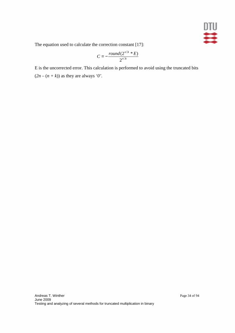
The equation used to calculate the correction constant [17]:
kn
kn EroundC +
+
−=2
)*2(
E is the uncorrected error. This calculation is performed to avoid using the truncated bits
(2n – (n + k)) as they are always ‘0’ .

Andreas T. Winther June 2009 Testing and analyzing of several methods for truncated multiplication in binary
Page 35 of 94
Table 1: Precision error for various truncated multipliers Each row represents a multiplier defined by the parameters n, k and T.
n k T E[not corrected] C E[corrected] Inputs
8 1 7 -130.253771 130.2539 -5.965983 1,000,000 8 2 6 -49.368171 49.36816 -6.347613 1,000,000 8 3 5 -16.653515 16.65332 -4.954989 1,000,000 8 4 4 -4.2326551 4.232666 -0.30413 1,000,000 8 5 3 -0.053813 0.053833 0.391538 1,000,000 8 8 0 1.599285 -1.599289 -0.69136 1,000,000
15 1 14 -45064.90 45064.90 -9.476291 1,000,000 15 2 13 -20507.77 20507.77 17.29518 1,000,000 15 3 12 -9216.607 9216.607 5.324396 1,000,000 15 4 11 -4114.335 4144.335 43.53750 1,000,000 15 5 10 -1807.960 1807.960 -4.668613 1,000,000 15 6 9 -795.4281 795.4281 8.099846 1,000,000 15 7 8 -343.2297 343.2297 43.11340 1,000,000 15 15 0 58.83136 -58.83136 -59.64291 1,000,000
16 1 15 -59592.17 59592.17 OVERFLOW 1,000,000 16 2 14 -45049.86 45049.86 OVERFLOW 1,000,000 16 3 13 -37639.47 37639.48 OVERFLOW 1,000,000 16 4 12 -286374.2 286374.2 OVERFLOW 1,000,000 16 5 11 -25537.30 25537.30 OVERFLOW 1,000,000 16 6 10 -31825.38 31825.38 OVERFLOW 1,000,000 16 16 0 -30026.22 30026.22 OVERFLOW 1,000,000
32 1 31 OVERFLOW OVERFLOW OVERFLOW - 32 2 30 OVERFLOW OVERFLOW OVERFLOW - 32 3 29 OVERFLOW OVERFLOW OVERFLOW - 32 4 28 OVERFLOW OVERFLOW OVERFLOW - 32 5 27 OVERFLOW OVERFLOW OVERFLOW - 32 6 26 OVERFLOW OVERFLOW OVERFLOW - 32 7 25 OVERFLOW OVERFLOW OVERFLOW - 32 8 24 OVERFLOW OVERFLOW OVERFLOW - 32 32 0 OVERFLOW OVERFLOW OVERFLOW -

Andreas T. Winther June 2009 Testing and analyzing of several methods for truncated multiplication in binary
Page 36 of 94
6.1.2 Hardware savings
In Table 2 the hardware savings for various truncated multipliers (with n, k and T as
defining parameters) are presented. The number of 4 input LUTs are used to calculate the
Area Savings column. The synthesis reports used for this table can be found in Appendix
D – Synthesis reports.
Table 2: Hardware savings for various truncated multipliers Each row represents a multiplier defined by the parameters n, k and T.
n k T Look Up Tables (LUTs) Slices used Hardware savings
8 1 7 77 44 34.75 % 8 2 6 88 51 25.42% 8 3 5 99 57 16.10 % 8 4 4 106 61 10.17 % 8 5 3 111 64 5.932 % 8 8 0 118 68 0.000 %
16 1 15 286 164 42.11 % 16 2 14 313 180 36.64 % 16 3 13 339 195 31.38 % 16 4 12 363 209 26.52 % 16 5 11 384 221 22.27 % 16 6 10 404 232 18.22 % 16 16 0 494 284 0.000 %
32 1 31 1086 624 46.08 % 32 2 30 1145 658 43.15 % 32 3 29 1203 692 40.27 % 32 4 28 1259 724 27.49 % 32 5 27 1312 754 24.86 % 32 6 26 1364 784 32.27 % 32 7 25 1414 813 29.79 % 32 8 24 1461 840 27.46 % 32 32 0 2014 1158 0.000 %

Andreas T. Winther June 2009 Testing and analyzing of several methods for truncated multiplication in binary
Page 37 of 94
7 Discussion
In this chapter, the results presented in this report are discussed and compared with
similar previously published results. It will also be discussed whether the tools, methods
and components used were correct. Finally the perspectives of the work and what future
work could be done are discussed.
7.1 Results evaluation
7.1.1 Precision Error
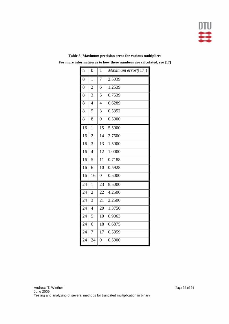
Theoretical calculations similar to the experimental results in this project are presented in
[17]. In both cases, the average error follows no pattern with a precision error that is more
or less independent of the degree of truncation (after correction is applied). Therefore,
one is lead to believe that a high level of truncation should be applied as its downsides are
the same as for a low degree of truncation. In [17] however another calculation is
calculated, maximum error, which describes the highest possible deviation from the
correct result for a single sample. The values are shown in Table 3. This value follows a
pattern and it is obvious that a higher degree of truncation leads to a higher maximum
error. Based on this information it is a matter of precision constraints that determines
what degree of truncation would be best.
Andreas T. Winther June 2009 Testing and analyzing of several methods for truncated multiplication in binary
Page 38 of 94
Table 3: Maximum precision error for various multip liers
For more information as to how these numbers are calculated, see [17]
n k T Maximum error([17])
8 1 7 2.5039
8 2 6 1.2539
8 3 5 0.7539
8 4 4 0.6289
8 5 3 0.5352
8 8 0 0.5000
16 1 15 5.5000
16 2 14 2.7500
16 3 13 1.5000
16 4 12 1.0000
16 5 11 0.7188
16 6 10 0.5928
16 16 0 0.5000
24 1 23 8.5000
24 2 22 4.2500
24 3 21 2.2500
24 4 20 1.3750
24 5 19 0.9063
24 6 18 0.6875
24 7 17 0.5859
24 24 0 0.5000

Andreas T. Winther June 2009 Testing and analyzing of several methods for truncated multiplication in binary
Page 39 of 94
7.1.2 Hardware savings
Table 4 shows hardware savings for various multipliers compared with [17].
Table 4: Hardware savings compared with [17]
n k T Hardware savings Hardware savings ([17])
8 1 7 34.75 % 35.4 %
8 2 6 25.42% 23.9 %
8 3 5 16.10 % 15.2 %
8 4 4 10.17 % 9.28 %
8 5 3 5.932 % 4.36 %
8 8 0 0.000 % 0,00 %
16 1 15 42.11 % 42.6 %
16 2 14 36.64 % 40.0 %
16 3 13 31.38 % 34.2 %
16 4 12 26.52 % 29.3 %
16 5 11 22.27 % 24.2 %
16 6 10 18.22 % 19.9 %
16 16 0 0.000 % 0.00 %
32 1 31 46.08 % -
32 2 30 43.15 % -
32 3 29 40.27 % -
32 4 28 27.49 % -
32 5 27 24.86 % -
32 6 26 32.27 % -
32 7 25 29.79 % -
32 8 24 27.46 % -
32 32 0 0.000 % -

Andreas T. Winther June 2009 Testing and analyzing of several methods for truncated multiplication in binary
Page 40 of 94
In [17] the results are based on theoretical calculations and in this project they are based
on experimental results. It can be seen that the experimental results from this project are
in agreement with [17]. In [17] it is stated about the values in Table 4:
The same model is implemented in this project as in [17] except for three things:
• Relative sizes are used in [17].
• n half adders are used in [17] instead of full adders, where n is the size of the
inputs. Since half adders and full adders have the same relative size in [17] this
does not affect the results.
• A simpler full-array multiplier is used in [17] compared to the CSA’s used in this
project. The area used, however, is equivalent as it is only a matter of how the
carries are passed on.
These differences are judged as minor differences, which can explain the deviations in
Table 4. They do not affect the overall conclusion.
7.2 Simulink
As mentioned previously overflow occurs when using Simulink to simulate the multiplier
for inputs of more than 15 bits and this immediately raises the question if Simulink is
even the right tool. It is an easy readily understood tool with a user-friendly interface but
it is not as powerful as other tools (E.g. Matlab). The multiplier itself was implemented
using an Embedded Matlab Function but these inherit the restrictions enforced on
“… the values given correspond to the hardware savings of truncated multipliers compared with conventional multipliers which implement round to nearest by adding a one to column n-1. For this table, the relative sizes of the AND gates, half adders and full adders are 1, 4 and 9, respectively. The relative size of each full adder in the CLA is 9 and a 4-bit CLA logic block has a relative size of 20.” [17]

Andreas T. Winther June 2009 Testing and analyzing of several methods for truncated multiplication in binary
Page 41 of 94
Simulink and are as such not as useful as pure Matlab functions. It is therefore suggested
to implement the model using only the Matlab programming language.
7.3 Perspectives
Truncation is a method widely used. There are great possibilities in using truncation as it
has always been a concern problem to reduce area-on-chip along with power dissipation
and complexity of the components. Some of the many examples of use can be found in
[1], [2], [4], [5], [18].
7.4 Future work
The field of truncating multipliers is quite big and there are many different ways of
performing truncation and very different hardware can be used as mentioned in Chapter
3. Immediate future work could be to extend to multiple multipliers and/or multipliers
that form the partial product matrix through other techniques (e.g. modified booth
encoding [1], [18]). It could also be to implement more intricate adders or correction
methods.
Specific for this project, correcting the Simulink model or rewriting it completely using
the Matlab programming language is a pending problem. Also, simulating the maximum
error would be helpful as such a table is very helpful when deciding the degree of
truncation to use.
Andreas T. Winther June 2009 Testing and analyzing of several methods for truncated multiplication in binary
Page 42 of 94
8 Conclusion
In this project n-1 Carry-save adders and one Carry look-ahead adder were used to
implement a parallel multiplier with truncation, where n is the width of the inputs.
To get the precision error a Simulink model was designed and implemented. Using inputs
of more than 15-bits caused overflow. This made simulations unreliable and raised the
question whether Simulink was the right tool. Using standard Matlab programming was
suggested. The results though clearly demonstrated how truncation introduced large
errors but also how those errors could be reduced to an acceptable level by introducing a
simple correction constant. In [17] the maximum precision error of a single sample on a
similar multiplier was predicted using theoretical calculations. These revealed that the
maximum error increased as the degree of the truncation increased. Lastly, more complex
correction methods could be used to reduce the precision error even further but this was
not within the scope of this project [12], [13], [14], [15].
The Multiplier was also implemented and simulated in ModelSim using the hardware
description language VHDL. Furthermore the VHDL model was synthesized using Xilinx
ISE to evaluate hardware savings. This showed that hardware savings of up to 46.08 %
for 32-bit inputs could be achieved. The hardware savings from this project were also
compared with [17]. It was found that the theoretical predictions made in [17] and the
results presented in this project were in agreement.
To conclude the project it can be said that even high levels of truncation lead to a
relatively small precision error. This means that truncated multipliers offer significant
hardware savings for applications, which do not require exact multiplication. Given
specific hardware and precision constraints, the right number of columns to truncate for
8, 16 and 32 bits can easily be determined. Future work could be to extend to multiple
multipliers and/or multipliers that form the partial product matrix through other

Andreas T. Winther June 2009 Testing and analyzing of several methods for truncated multiplication in binary
Page 43 of 94
techniques (e.g. modified booth encoding [1], [18]). Some examples of use can be found
in [1], [2], [4], [5], [18].
Andreas T. Winther June 2009 Testing and analyzing of several methods for truncated multiplication in binary
Page 44 of 94
9 References
[1] Tso-Bin Juang, Shen-Fu-Hsiao, Low-Error Carry-Free Fixed-Width Multipliers
With Low-Cost Composation Circuits, IEEE Transactions on circuits and
systems-II: Express briefs, Vol. 52, No. 6, June 2005, (.PDF file).
[2] E. George Walters III, Mark G. Arnold, Michael J. Schulte, Using Truncated
Multipliers in DCT and IDCT hardware accelerators, (.PDF file).
[3] Sunder S. Kidambi, Fayez El-Guibaly, Andreas Antoniou, Area-Efficient
Multipliers for Digital Signal Processing Applications, IEEE Transactions on
Circuits and Systems—II: Analog and Digital Signal Processing, Vol. 43, No. 2,
February 1996, (.PDF file).
[4] Florean Curticapean, Jarkko Niitylahti, A Hardware Efficient Direct Digital
Frequency Synthesizer, Tampere (.PDF file).
[5] E. George Walters III, Michael J. Schulte, Design Tradeoffs Using Truncated
Multipliers In FIR Filter implementations, Lehigh University, (.PDF file)
[6] http://www.systemc.org/home (last visited 24/6-2009).
[7] http://www.systemverilog.org/ (last visited 24/6-2009)
[8] Prof. Loh - Carry-Save Addition, CS3220 – Processor Design – February 2,
2005, (.PDF file).
[9] http://www.aoki.ecei.tohoku.ac.jp/arith/mg/algorithm.html (last visited 24/6-
2009)
[10] http://www.statemaster.com/encyclopedia/Adder-(electronics), homepage, last
visited 21/7-2009.
[11] David A. Patterson, John L. Hennesey, Computer Organization And Design –
The Hardware/Software Interface, 3rd edition, revised printing, Morgan
Kaufmann publishers, 2007, ISBN: 978-0-12-370606-5.
[12] Lan-Da Van, Chih-Chyau Yang, Generalized Low-Error Area-Efficient Fixed-
Width Multipliers, (.PDF file).
[13] Eric J. King, Earl E. Swartzlander, Jr. Data-Dependent Truncation Scheme for
Parallel Multipliers, Texas, (.PDF file).

Andreas T. Winther June 2009 Testing and analyzing of several methods for truncated multiplication in binary
Page 45 of 94
[14] E. George Walters III, Michael J. Schulte, Efficient Function Approximation
Using Truncated Multipliers and Squarers, USA, (.PDF file).
[15] James E. Stine, Oliver M. Duverne, Variations on Truncated Multiplication,
Illinois, (.PDF file)
[16] Peter J. Ashenden, The Designer’s Guide To VHDL, 2nd Edition, 1996, ISBN:
1-55860-674-2.
[17] Michael J. Schulte, Earl E. Swartzlander, Jr., Truncated Multiplication with
Correction Constant, (.PDF file).
[18] Alok A. Katkar, james E. Stine, Modified Booth Truncated Multipliers, Illinois
(.PDF file)
Pictures and homepages of tools used are referenced to directly in the report.

Andreas T. Winther June 2009 Testing and analyzing of several methods for truncated multiplication in binary
Page 46 of 94
10 Appendix A – Matlab Simulink Design
This appendix unrolls the Matlab Simulink model. Below is the inside of the block sub-systems along with the full source code for the embedded Matlab function.
10.1 The inside of the Simulink sub-systems As mentioned before the inside of the sub-systems are simply built-in Matlab Simulink building blocks.
Figure 19: The rounding sub-system
The input is converted to a 32bit integer, a constant is added and the integer is first right shifted, then lefting shifted (here 8 bits each way). This is done to simulate the rounding error.
Figure 20: The Random Number Generator sub-system
Two random numbers are generated and converted to 32-bit integers.
Figure 21: The Average Calc sub-system
The first part of the subsystem takes the sum of all samples and the second part divides with the number of samples performed at any given time. The block “Counter” functions as a +1 counter.

Andreas T. Winther June 2009 Testing and analyzing of several methods for truncated multiplication in binary
Page 47 of 94
10.2 Matlab embedded function full source code function sum = Multiplier( a,b,n,k) % nxn bit multiplier with truncation. n determines the width of the inputs, % and k determines the level of truncation abin=zeros(1,n); bbin=zeros(1,n); m=0; carry=0; sum=0; %Sum in base 10 (output=integer) sumbin=zeros(1,2*n); % sum in base 2 (output=vector) y=zeros(n,2*n); %initiation of a (n x n*2) matrix %%%Here the integer input is converted to a binary array for j = 1:n if a-pow2(n-j) >= 0 %% first for a abin(j)=1; a=a-pow2(n-j); else abin(j)=0; end if b-pow2(n-j) >= 0 %% then for b bbin(j)=1; b=b-pow2(n-j); else bbin(j)=0; end end %%% Partiel product matrix is generated here for i = n:-1:1 %from n downto 1 m=m+1; for j = 1:n %from 1 to n y(m,n+1+j-m) = abin(j)&bbin(i); end end %%% Here truncation is introduced to the matrix for i = 1:n for j = n+k+1:n*2 %The part is truncated away y(i,j) = 0; end end %%% Here the calculation itself is made for j = n*2:-1:1 for i = 1:n sumbin(j) = sumbin(j) + y(i,j); end sumbin(j) = sumbin(j) + carry; %% adding previous carry carry = floor(sumbin(j)/2); %% finding new carry
Andreas T. Winther June 2009 Testing and analyzing of several methods for truncated multiplication in binary
Page 48 of 94
sumbin(j) = sumbin(j) - carry * 2; %% setting final partiel product produkt end %%% Here the binary sum vector is converted to back to an integer for j = 0:n*2-1 sum = sum + sumbin(2*n-j)*pow2(j); end int32(sum); end

Andreas T. Winther June 2009 Testing and analyzing of several methods for truncated multiplication in binary
Page 49 of 94
11 Appendix B - VHDL code
11.1 Nxn_mult.vhd library IEEE; use IEEE.std_logic_1164.all; use IEEE.numeric_std.all; use ieee.std_logic_unsigned.all; entity Mult is generic ( left : natural := 7; -- position of MSB T : integer := 7 -- truncation of 0 means no truncation ); port ( a : in std_logic_vector(left downto 0); b : in std_logic_vector(left downto 0); -- y_round: out std_logic_vector(left downto 0); --only used for rounding y : out std_logic_vector(2*left+1 downto 0) ); end Mult; architecture circuits of Mult is constant zero : std_logic_vector(left downto 0) := (others => '0'); signal nc1 : std_logic; type arr is array(0 to left) of std_logic_vector(left downto 0); signal c : arr := (others => (others => '0')); -- carries equals amount of adders signal s : arr := (others => (others => '0')); -- partial sums signal ss : arr := (others => (others => '0')); -- shifted sums component CSA_g -- duplicates entity port generic ( left : integer; T : integer ); port ( b : in std_logic; -- a multiplier bit a : in std_logic_vector(left downto 0); -- multiplicand sum_in : in std_logic_vector(left downto 0); -- sums from previous stage cin : in std_logic_vector(left downto 0); -- carrys from previous stage sum_out : out std_logic_vector(left downto 0); -- sums to next stage cout : out std_logic_vector(left downto 0) -- carrys to next stage ); end component CSA_g;

Andreas T. Winther June 2009 Testing and analyzing of several methods for truncated multiplication in binary
Page 50 of 94
component CLA_g -- duplicates entity port generic(left: integer); port (a : in std_logic_vector (left downto 0); b : in std_logic_vector (left downto 0); cin : in std_logic; sum : out std_logic_vector (left downto 0); cout : out std_logic ); end component CLA_g; begin -- circuits of Mult --for truncation. Only affects p(0) trunc: process(a,b,s) is begin if (T > 0 and b(0) = '1' ) then s(0) <= a(left downto 1)&'0'; elsif (T = 0 and b(0) = '1') then s(0) <= a; else -- if b(0) = '0' it doesnt matter what T is s(0) <= zero; end if; end process trunc; ss(0) <= '0'&s(0)(left downto 1); y(0) <= s(0)(0); -- VHDL 'generate' to have less statements stage: for I in 1 to left generate st: CSA_g generic map(left,T-I) --position of MSB and level of truncation port map(b(I), a, ss(I-1), c(I-1), s(I), c(I)); ss(I) <= '0'&s(I)(left downto 1); y(I) <= s(I)(0); end generate stage; add: CLA_g generic map(left) port map(ss(left), c(left), '0', y(left*2+1 downto left+1), nc1); -- Use this adder instead for rounding to left+1 bits

Andreas T. Winther June 2009 Testing and analyzing of several methods for truncated multiplication in binary
Page 51 of 94
-- add_round: CLA_g -- generic map(left) -- port map(ss(left), c(left), y(left), y_round(left downto 0), nc1); end architecture circuits; -- of Mult
11.2 Components.vhd library IEEE; use IEEE.std_logic_1164.all; entity fadd is -- a, b and the carry-in ci are inputs of the adder. -- s is the sum output, co is the carry-out. port ( a, b : in std_logic; cin : in std_logic; s : out std_logic; cout : out std_logic ); end fadd; architecture circuits of fadd is begin -- This full-adder architecture contains two concurrent assignment. -- Compute the sum. s <= a xor b xor cin; -- Compute the carry. cout <= (a and b) or (a and cin) or (b and cin); end circuits; --Carry-look ahead adder n-bit adder used as the final adder LIBRARY IEEE; USE IEEE.std_logic_1164.ALL; entity CLA_g IS generic(left : natural := 31 -- top bit ); port (a : in std_logic_vector (left downto 0); b : in std_logic_vector (left downto 0); cin : in std_logic; sum : out std_logic_vector (left downto 0); cout : out std_logic );

Andreas T. Winther June 2009 Testing and analyzing of several methods for truncated multiplication in binary
Page 52 of 94
end CLA_g; architecture circuits OF CLA_g IS signal h_sum : std_logic_vector(left downto 0); signal carry_generate : std_logic_vector(left downto 0); signal carry_propagate : std_logic_vector(left downto 0); signal carry_in_internal : std_logic_vector(left downto 1); begin h_sum <= a xor b; carry_generate <= a and b; carry_propagate <= a or b; process (carry_generate,carry_propagate,carry_in_internal,cin) begin carry_in_internal(1) <= carry_generate(0) or (carry_propagate(0) and cin); inst: for i in 1 to left-1 loop carry_in_internal(i+1) <= carry_generate(i) or (carry_propagate(i) and carry_in_internal(i)); end loop; cout <= carry_generate(left) or (carry_propagate(left) and carry_in_internal(left)); end process; sum(0) <= h_sum(0) xor cin; sum(left downto 1) <= h_sum(left downto 1) xor carry_in_internal(left downto 1); end circuits; library IEEE; use IEEE.std_logic_1164.all; entity CSA_g is generic( left : integer := 7; T : integer := 0 --0 means no truncation ); port( b : in std_logic; -- a multiplier bit a : in std_logic_vector(left downto 0); -- multiplicand sum_in : in std_logic_vector(left downto 0); -- sums from previous stage cin : in std_logic_vector(left downto 0); -- carrys from previous stage sum_out : out std_logic_vector(left downto 0) := (others => '0'); -- sums to next stage cout : out std_logic_vector(left downto 0) := (others => '0') -- carrys to next stage );

Andreas T. Winther June 2009 Testing and analyzing of several methods for truncated multiplication in binary
Page 53 of 94
end CSA_g; architecture circuits of CSA_g is signal zero : std_logic_vector(left downto 0) := (others => '0'); signal aa : std_logic_vector(left downto 0) := (others => '0'); component fadd -- duplicates entity port port(a : in std_logic; b : in std_logic; cin : in std_logic; s : out std_logic; cout : out std_logic); end component fadd; begin -- circuits of CSA_g -- If T is negative just use 0 as T aa <= a when b = '1' else zero; s1: IF T < 0 generate st1: for I in 0 to left generate sta: fadd port map(aa(I), sum_in(I), cin(I) , sum_out(I), cout(I)); end generate st1; end generate s1; s2: IF T >= 0 generate st2: for I in T to left generate sta: fadd port map(aa(I), sum_in(I), cin(I) , sum_out(I), cout(I)); end generate st2; end generate s2; end architecture circuits; -- of CSA_g -- This is the generic n-bit adder and the CLA_g was used to compare hardware savings. -- It was found that the area used was the same for the two. library IEEE; use IEEE.std_logic_1164.all; entity add_g is --generic n-bit adder generic(left : natural := 31 -- top bit ); port (a : in std_logic_vector (left downto 0); b : in std_logic_vector (left downto 0); cin : in std_logic; sum : out std_logic_vector (left downto 0); cout : out std_logic); end add_g;

Andreas T. Winther June 2009 Testing and analyzing of several methods for truncated multiplication in binary
Page 54 of 94
architecture circuits of add_g is signal isum : std_logic_vector(left downto 0); -- internal signal carry : std_logic_vector(left+1 downto 0); -- internal begin -- circuits carry(0) <= cin; adder: for i in 0 to left generate isum(i) <= a(i) xor b(i) xor carry(i); carry(i+1) <= (a(i) and b(i)) or (a(i) and carry(i)) or (b(i) and carry(i)); end generate adder; sum <= isum; cout <= carry(left+1); end architecture circuits; -- of add_g
11.3 Testbench.vhd library IEEE; use IEEE.std_logic_1164.all; entity testbench is end testbench; architecture arch32 of testbench is signal a_i,b_i:std_logic_vector(31 downto 0); --signal y_i_round: std_logic_vector(31 downto 0); type arr is array(0 to 31) of std_logic_vector(63 downto 0); signal y : arr; -- All the 32-bit products of the testbench begin --this generate loop generates 31 multipliers with the same inputs but --31 different levels of truncation (T=0 => T=31) stage: for I in 0 to 31 generate mult: entity work.Mult(circuits) -- K = N-T generic map(left => 31,T => I) --position of MSB and level of truncation port map(a_i,b_i,y(I)); -- add y_i_round if rounding is needed end generate stage;

Andreas T. Winther June 2009 Testing and analyzing of several methods for truncated multiplication in binary
Page 55 of 94
stimulus: process begin a_i<=X"11111111";b_i<=X"11111111"; wait for 10 ns; if now=10 ns then wait; end if; end process stimulus; end arch32; architecture arch16 of testbench is signal a_i,b_i:std_logic_vector(15 downto 0); -- signal y_i_round: std_logic_vector(15 downto 0); signal y_i: std_logic_vector(31 downto 0); begin mult: entity work.Mult(circuits) -- K = N-T generic map(left => 15,T => 4) --position of MSB and level of truncation port map(a_i,b_i,y_i); -- add y_i_round if rounding is needed stimulus: process begin a_i<="1011101110111011";b_i<="1100110011001100"; wait for 10 ns; a_i<="0111011101110111";b_i<="1011101110111011"; wait for 10 ns; a_i<="1101110111011101";b_i<="0111011101110111"; wait for 10 ns; a_i<="1111111111111111";b_i<="0010001000100010"; wait for 10 ns; a_i<="1101110111011101";b_i<="1000100010001000"; wait for 10 ns; a_i<="1111111111111111";b_i<="1111111111111111"; wait for 10 ns; a_i<="1111111111111111";b_i<="0010001000100010"; wait for 10 ns; a_i<="1011101110111011";b_i<="1011101110111011"; wait for 10 ns;

Andreas T. Winther June 2009 Testing and analyzing of several methods for truncated multiplication in binary
Page 56 of 94
a_i<="0110011001100110";b_i<="1010101010101010"; wait for 10 ns; a_i<="1101110111011101";b_i<="1010101010101010"; wait for 10 ns; if now=100 ns then wait; end if; end process stimulus; end arch16; architecture arch8 of testbench is signal a_i,b_i:std_logic_vector(7 downto 0); -- signal y_i_round: std_logic_vector(7 downto 0); signal y_i: std_logic_vector(15 downto 0); begin mult: entity work.Mult(circuits) -- K = N-T generic map(left => 7,T => 0) --position of MSB and level of truncation port map(a_i,b_i,y_i); -- add y_i_round if rounding is needed stimulus: process begin a_i<="10111010";b_i<="11011100"; wait for 10 ns; a_i<="01111010";b_i<="10101111"; wait for 10 ns; a_i<="11001011";b_i<="01110101"; wait for 10 ns; a_i<="11111111";b_i<="00010010"; wait for 10 ns; a_i<="11000001";b_i<="10001000"; wait for 10 ns; a_i<="11111111";b_i<="11111111"; wait for 10 ns; a_i<="11110101";b_i<="00001011"; wait for 10 ns; a_i<="11011011";b_i<="10101101"; wait for 10 ns; a_i<="00110110";b_i<="10000110"; wait for 10 ns;
Andreas T. Winther June 2009 Testing and analyzing of several methods for truncated multiplication in binary
Page 57 of 94
a_i<="11010110";b_i<="10100110"; wait for 10 ns; if now=100 ns then wait; end if; end process stimulus; end arch8; --arch4 with only 4 bits inputs is used for testing since --it is easy to follow using the "pen and paper" method architecture arch4 of testbench is signal a_i,b_i:std_logic_vector(3 downto 0); --signal y_i_round: std_logic_vector(3 downto 0); signal y_i_3: std_logic_vector(7 downto 0); signal y_i_2: std_logic_vector(7 downto 0); signal y_i_1: std_logic_vector(7 downto 0); signal y_i_0: std_logic_vector(7 downto 0); begin mult_3: entity work.Mult(circuits) -- K = N-T generic map(left => 3,T => 3) --position of MSB and level of truncation port map(a_i,b_i,y_i_3); -- add y_i_round if rounding is needed mult_2: entity work.Mult(circuits) -- K = N-T generic map(left => 3,T => 2) --position of MSB and level of truncation port map(a_i,b_i,y_i_2); -- add y_i_round if rounding is needed mult_1: entity work.Mult(circuits) -- K = N-T generic map(left => 3,T => 1) --position of MSB and level of truncation port map(a_i,b_i,y_i_1); -- add y_i_round if rounding is needed mult_0: entity work.Mult(circuits) -- K = N-T generic map(left => 3,T => 0) --position of MSB and level of truncation port map(a_i,b_i,y_i_0); -- add y_i_round if rounding is needed stimulus: process begin

Andreas T. Winther June 2009 Testing and analyzing of several methods for truncated multiplication in binary
Page 58 of 94
a_i<="0000";b_i<="0000"; wait for 10 ns; a_i<="1111";b_i<="1111"; wait for 10 ns; a_i<="0000";b_i<="1111"; wait for 10 ns; a_i<="1111";b_i<="0000"; wait for 10 ns; a_i<="1100";b_i<="1100"; wait for 10 ns; a_i<="0011";b_i<="0011"; wait for 10 ns; a_i<="1010";b_i<="0101"; wait for 10 ns; if now=70 ns then wait; end if; end process stimulus; end arch4;

Andreas T. Winther June 2009 Testing and analyzing of several methods for truncated multiplication in binary
Page 59 of 94
12 Appendix C – Test results This appendix has an example of a Simulink test bench and the simulation diagrams from modelSim.
12.1 Simulink test bench In Figure 22 a Simulink test bench is shown. The parameters used for this example is n = 8, k = 4, C = 0. Most signals are represented both using unsigned and binary numbers. If you follow the before mentioned Branch B (the branch with truncation, rounding and correction etc) it is seen how the last 4 bits are ‘0’ and how the rounding is afterwards applied by adding a ‘1’ to the appropriate bit and then left + right shifting. A brief explanation of what the displays show follows: Display : Shows the final result in signed representation. Display 1 : Shows the X output in binary representation. Display 2 : Shows the Y output in binary representation. Display 3 : Shows the X output in signed representation. Display 4 : Shows the X the product after truncation, rounding and correction in binary. Display 5 : Shows the X the product after truncation, rounding and correction in signed. Display 6 : Shows the product after truncation, before rounding in binary. Display 7 : Shows the product after truncation and rounding in binary. Display 8 : Shows the product after truncation, before rounding in signed. Display 9 : Shows the precision error in signed. Display 12: Shows the product after truncation and rounding in signed.

Andreas T. Winther June 2009 Testing and analyzing of several methods for truncated multiplication in binary
Page 60 of 94
Figure 22: Simulink test bench example

Andreas T. Winther June 2009 Testing and analyzing of several methods for truncated multiplication in binary
Page 61 of 94
12.2 Simulation diagrams from modelSim Below are given several diagrams from the modelsim testbench simulations. The products are represented using red squares.
Figure 23: left = 3, T = 3. Binary representation It is seen that since T = 3, the four last product bits are always ‘0’ due to truncation. Going through
these results using the pen-and-paper method shows that the results are correct.

Andreas T. Winther June 2009 Testing and analyzing of several methods for truncated multiplication in binary
Page 62 of 94
Figure 24: left = 3, T = 3. Unsigned representation. Like in picture Figure 23 but with unsigned representation. Notice how the products are a bit too
small compared to the real product. This is expected as some ‘1’s are lost due to truncation.

Andreas T. Winther June 2009 Testing and analyzing of several methods for truncated multiplication in binary
Page 63 of 94
Figure 25: Left = 31, T = 0 - 28. Binary representation 29 multipliers are shown above with degree of truncation T = 0 – 31. Notice how the T least
significant bits (everything right of the red line) of the products are all ‘0’ .

Andreas T. Winther June 2009 Testing and analyzing of several methods for truncated multiplication in binary
Page 64 of 94
Figure 26: Left = 31, T = 0 - 28. Unsigned representation 29 multipliers are shown above with degree of truncation T = 0 – 31. The products become smaller
as the degree of truncation increases. This is expected as some ‘1’s are lost due to truncation.

Andreas T. Winther June 2009 Testing and analyzing of several methods for truncated multiplication in binary
Page 65 of 94
Figure 27: left = 3, T = 0 - 3. Binary representation 4 multipliers are shown all with the same inputs (a and b). Mult_0 has no truncation, Mult_1 has truncation degree T = 1 and so on. Notice how the least significant bits become 0 when truncation
increases. The bottom of this diagram unrolls the signals of Mult_3.
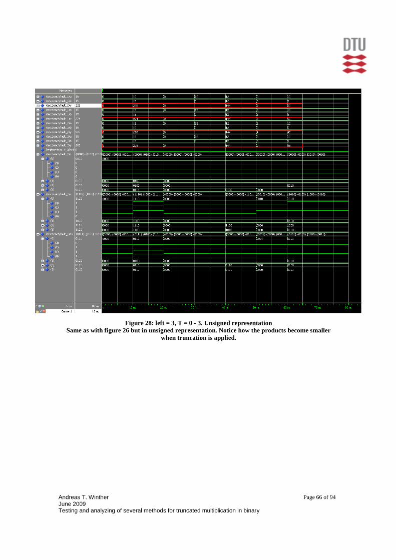
Andreas T. Winther June 2009 Testing and analyzing of several methods for truncated multiplication in binary
Page 66 of 94
Figure 28: left = 3, T = 0 - 3. Unsigned representation Same as with figure 26 but in unsigned representation. Notice how the products become smaller
when truncation is applied.

Andreas T. Winther June 2009 Testing and analyzing of several methods for truncated multiplication in binary
Page 67 of 94
13 Appendix D – Synthesis reports The model was synthesized with focus on uploading to a Spartan 2, XC2S200 board. First is the comparison of area-on-chip usage for a generic Ripple-carry adder and a generic Carry look-ahead adder. Second, the area specific fragments of synthesis reports for various truncated multipliers are given and lastly an example of a full synthesis report is given.
13.1 CLA_g (Carry Look-ahead) VS add_g (Ripple-carry) As it can be seen they use the exact same amount of area on the chip.
13.2 32-bit input (left = 31)
k = 32 => T = 0 Device utilization summary: --------------------------- Selected Device : 2s200pq208-5 Number of Slices 1158 out of 2352 49% Number of 4 input LUTs: 2014 out of 4704 42% Number of IOs 128 Number of bonded IOBs: 128 out of 140 91%
CLA_g: Number of Slices: 37 out of 960 3% Number of 4 input LUTs: 64 out of 1920 3% Number of IOs: 98 Number of bonded IOBs: 98 out of 66 148% (*)
Add_G: Number of Slices: 37 out of 960 3% Number of 4 input LUTs: 64 out of 1920 3% Number of IOs: 98 Number of bonded IOBs: 98 out of 66 148% (*)

Andreas T. Winther June 2009 Testing and analyzing of several methods for truncated multiplication in binary
Page 68 of 94
k = 7 => T = 25
Device utilization summary: --------------------------- Selected Device : 2s200pq208-5 Number of Slices: 813 out of 2352 34% Number of 4 input LUTs: 1414 out of 4704 30% Number of IOs: 128 Number of bonded IOBs: 128 out of 140 91%
k = 6 => T = 26 Device utilization summary: --------------------------- Selected Device : 2s200pq208-5 Number of Slices: 784 out of 2352 33% Number of 4 input LUTs: 1364 out of 4704 28% Number of IOs: 128 Number of bonded IOBs: 128 out of 140 91%
k = 8 => T = 24 Device utilization summary: --------------------------- Selected Device : 2s200pq208-5 Number of Slices: 840 out of 2352 35% Number of 4 input LUTs: 1461 out of 4704 31% Number of IOs: 128 Number of bonded IOBs: 128 out of 140 91%

Andreas T. Winther June 2009 Testing and analyzing of several methods for truncated multiplication in binary
Page 69 of 94
k = 5 => T = 27 Device utilization summary: --------------------------- Selected Device : 2s200pq208-5 Number of Slices: 754 out of 2352 32% Number of 4 input LUTs: 1312 out of 4704 27% Number of IOs: 128 Number of bonded IOBs: 128 out of 140 91%
k = 4 => T = 28 Device utilization summary: --------------------------- Selected Device : 2s200pq208-5 Number of Slices: 724 out of 2352 30% Number of 4 input LUTs: 1259 out of 4704 26% Number of IOs: 128 Number of bonded IOBs: 128 out of 140 91%
k = 3 => T = 29 Device utilization summary: --------------------------- Selected Device : 2s200pq208-5 Number of Slices: 692 out of 2352 29% Number of 4 input LUTs: 1203 out of 4704 25% Number of IOs: 128 Number of bonded IOBs: 128 out of 140 91%
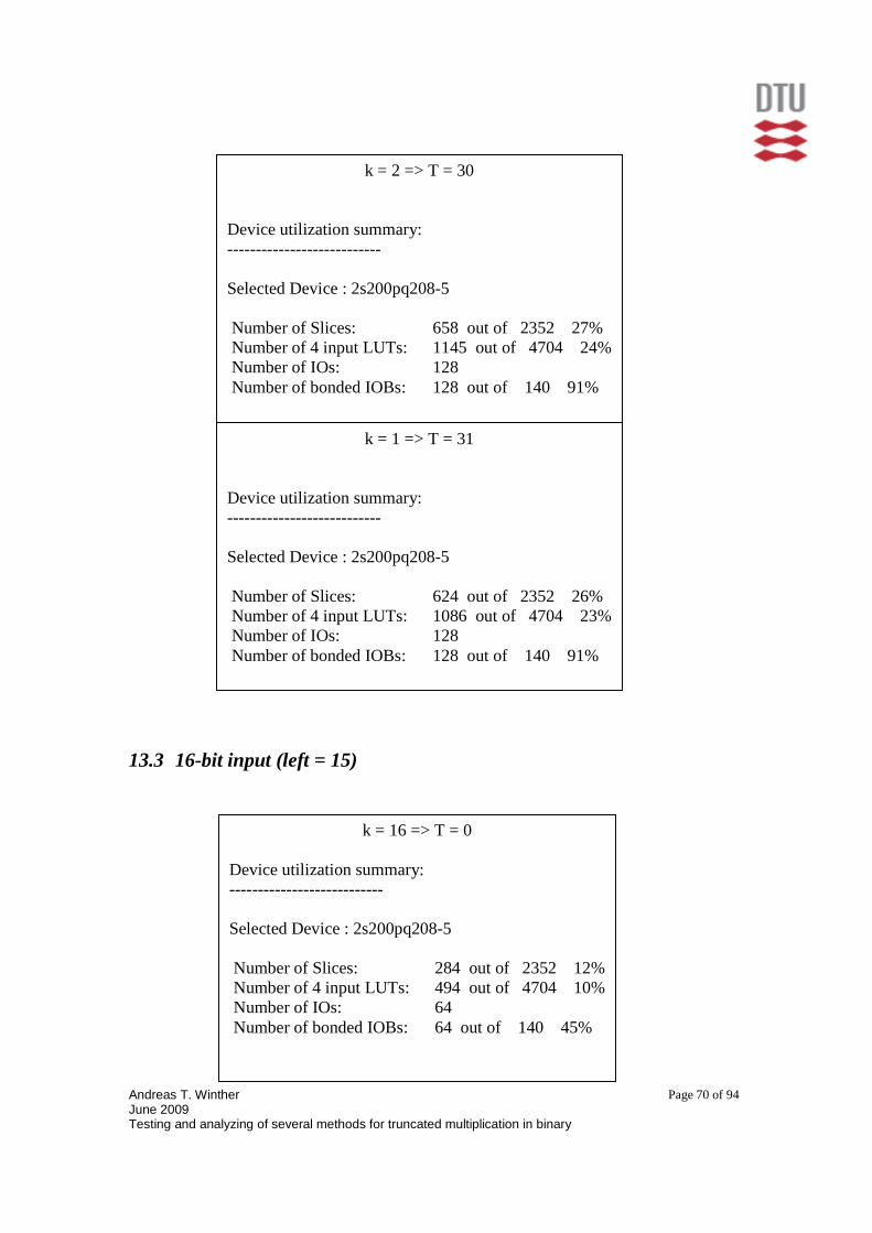
Andreas T. Winther June 2009 Testing and analyzing of several methods for truncated multiplication in binary
Page 70 of 94
13.3 16-bit input (left = 15)
k = 1 => T = 31 Device utilization summary: --------------------------- Selected Device : 2s200pq208-5 Number of Slices: 624 out of 2352 26% Number of 4 input LUTs: 1086 out of 4704 23% Number of IOs: 128 Number of bonded IOBs: 128 out of 140 91%
k = 2 => T = 30 Device utilization summary: --------------------------- Selected Device : 2s200pq208-5 Number of Slices: 658 out of 2352 27% Number of 4 input LUTs: 1145 out of 4704 24% Number of IOs: 128 Number of bonded IOBs: 128 out of 140 91%
k = 16 => T = 0 Device utilization summary: --------------------------- Selected Device : 2s200pq208-5 Number of Slices: 284 out of 2352 12% Number of 4 input LUTs: 494 out of 4704 10% Number of IOs: 64 Number of bonded IOBs: 64 out of 140 45%
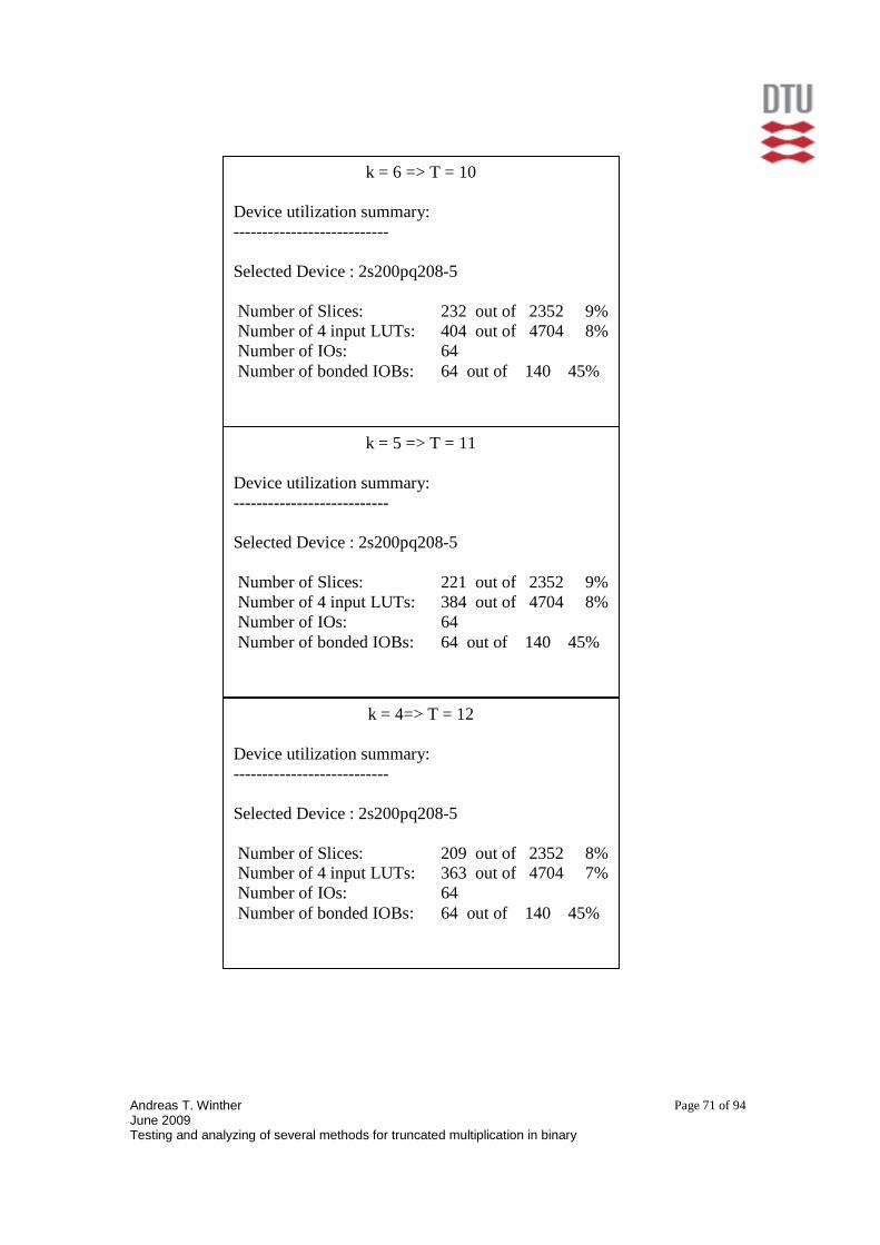
Andreas T. Winther June 2009 Testing and analyzing of several methods for truncated multiplication in binary
Page 71 of 94
k = 4=> T = 12 Device utilization summary: --------------------------- Selected Device : 2s200pq208-5 Number of Slices: 209 out of 2352 8% Number of 4 input LUTs: 363 out of 4704 7% Number of IOs: 64 Number of bonded IOBs: 64 out of 140 45%
k = 5 => T = 11 Device utilization summary: --------------------------- Selected Device : 2s200pq208-5 Number of Slices: 221 out of 2352 9% Number of 4 input LUTs: 384 out of 4704 8% Number of IOs: 64 Number of bonded IOBs: 64 out of 140 45%
k = 6 => T = 10 Device utilization summary: --------------------------- Selected Device : 2s200pq208-5 Number of Slices: 232 out of 2352 9% Number of 4 input LUTs: 404 out of 4704 8% Number of IOs: 64 Number of bonded IOBs: 64 out of 140 45%

Andreas T. Winther June 2009 Testing and analyzing of several methods for truncated multiplication in binary
Page 72 of 94
k = 1 => T = 15 Device utilization summary: --------------------------- Selected Device : 2s200pq208-5 Number of Slices: 164 out of 2352 6% Number of 4 input LUTs: 286 out of 4704 6% Number of IOs: 64 Number of bonded IOBs: 64 out of 140 45%
k = 2 => T = 14 Device utilization summary: --------------------------- Selected Device : 2s200pq208-5 Number of Slices: 180 out of 2352 7% Number of 4 input LUTs: 313 out of 4704 6% Number of IOs: 64 Number of bonded IOBs: 64 out of 140 45%
k = 3 => T = 13 Device utilization summary: --------------------------- Selected Device : 2s200pq208-5 Number of Slices: 195 out of 2352 8% Number of 4 input LUTs: 339 out of 4704 7% Number of IOs: 64 Number of bonded IOBs: 64 out of 140 45%

Andreas T. Winther June 2009 Testing and analyzing of several methods for truncated multiplication in binary
Page 73 of 94
13.4 8-bit input (left = 7)
k = 4 => T = 4 Device utilization summary: --------------------------- Selected Device : 2s200pq208-5 Number of Slices: 61 out of 2352 2% Number of 4 input LUTs: 106 out of 4704 2% Number of IOs: 32 Number of bonded IOBs: 32 out of 140 22%
k = 8 => T = 0 Device utilization summary: --------------------------- Selected Device : 2s200pq208-5 Number of Slices: 68 out of 2352 2% Number of 4 input LUTs: 118 out of 4704 2% Number of IOs: 32 Number of bonded IOBs: 32 out of 140 22%
k = 5 => T = 3 Device utilization summary: --------------------------- Selected Device : 2s200pq208-5 Number of Slices: 64 out of 2352 2% Number of 4 input LUTs: 111 out of 4704 2% Number of IOs: 32 Number of bonded IOBs: 32 out of 140 22%

Andreas T. Winther June 2009 Testing and analyzing of several methods for truncated multiplication in binary
Page 74 of 94
k = 1 => T = 7 Device utilization summary: --------------------------- Selected Device : 2s200pq208-5 Number of Slices: 44 out of 2352 1% Number of 4 input LUTs: 77 out of 4704 1% Number of IOs: 32 Number of bonded IOBs: 32 out of 140 22%
k = 2 => T = 6 Device utilization summary: --------------------------- Selected Device : 2s200pq208-5 Number of Slices: 51 out of 2352 2% Number of 4 input LUTs: 88 out of 4704 1% Number of IOs: 32 Number of bonded IOBs: 32 out of 140 22%
k = 3 => T = 5 Device utilization summary: --------------------------- Selected Device : 2s200pq208-5 Number of Slices: 57 out of 2352 2% Number of 4 input LUTs: 99 out of 4704 2% Number of IOs: 32 Number of bonded IOBs: 32 out of 140 22%
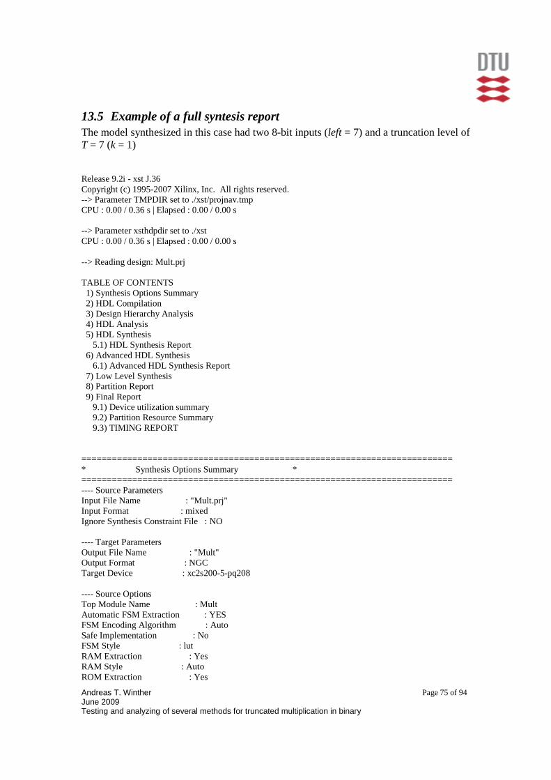
Andreas T. Winther June 2009 Testing and analyzing of several methods for truncated multiplication in binary
Page 75 of 94
13.5 Example of a full syntesis report The model synthesized in this case had two 8-bit inputs (left = 7) and a truncation level of T = 7 (k = 1) Release 9.2i - xst J.36 Copyright (c) 1995-2007 Xilinx, Inc. All rights reserved. --> Parameter TMPDIR set to ./xst/projnav.tmp CPU : 0.00 / 0.36 s | Elapsed : 0.00 / 0.00 s --> Parameter xsthdpdir set to ./xst CPU : 0.00 / 0.36 s | Elapsed : 0.00 / 0.00 s --> Reading design: Mult.prj TABLE OF CONTENTS 1) Synthesis Options Summary 2) HDL Compilation 3) Design Hierarchy Analysis 4) HDL Analysis 5) HDL Synthesis 5.1) HDL Synthesis Report 6) Advanced HDL Synthesis 6.1) Advanced HDL Synthesis Report 7) Low Level Synthesis 8) Partition Report 9) Final Report 9.1) Device utilization summary 9.2) Partition Resource Summary 9.3) TIMING REPORT ========================================================================= * Synthesis Options Summary * ========================================================================= ---- Source Parameters Input File Name : "Mult.prj" Input Format : mixed Ignore Synthesis Constraint File : NO ---- Target Parameters Output File Name : "Mult" Output Format : NGC Target Device : xc2s200-5-pq208 ---- Source Options Top Module Name : Mult Automatic FSM Extraction : YES FSM Encoding Algorithm : Auto Safe Implementation : No FSM Style : lut RAM Extraction : Yes RAM Style : Auto ROM Extraction : Yes

Andreas T. Winther June 2009 Testing and analyzing of several methods for truncated multiplication in binary
Page 76 of 94
Mux Style : Auto Decoder Extraction : YES Priority Encoder Extraction : YES Shift Register Extraction : YES Logical Shifter Extraction : YES XOR Collapsing : YES ROM Style : Auto Mux Extraction : YES Resource Sharing : YES Asynchronous To Synchronous : NO Multiplier Style : lut Automatic Register Balancing : No ---- Target Options Add IO Buffers : YES Global Maximum Fanout : 100 Add Generic Clock Buffer(BUFG) : 4 Register Duplication : YES Slice Packing : YES Optimize Instantiated Primitives : NO Convert Tristates To Logic : Yes Use Clock Enable : Yes Use Synchronous Set : Yes Use Synchronous Reset : Yes Pack IO Registers into IOBs : auto Equivalent register Removal : YES ---- General Options Optimization Goal : Speed Optimization Effort : 1 Library Search Order : Mult.lso Keep Hierarchy : NO RTL Output : Yes Global Optimization : AllClockNets Read Cores : YES Write Timing Constraints : NO Cross Clock Analysis : NO Hierarchy Separator : / Bus Delimiter : <> Case Specifier : maintain Slice Utilization Ratio : 100 BRAM Utilization Ratio : 100 Verilog 2001 : YES Auto BRAM Packing : NO Slice Utilization Ratio Delta : 5 ========================================================================= ========================================================================= * HDL Compilation * ========================================================================= Compiling vhdl file "//adserv1.imm.dtu.dk/users/s053010/Bachelor/VHDL_project/4x4/components.vhd" in Library work. Architecture circuits of Entity fadd is up to date. Architecture circuits of Entity cla_g is up to date.
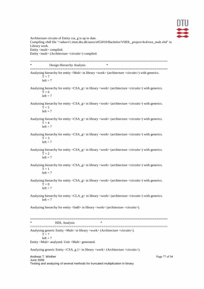
Andreas T. Winther June 2009 Testing and analyzing of several methods for truncated multiplication in binary
Page 77 of 94
Architecture circuits of Entity csa_g is up to date. Compiling vhdl file "//adserv1.imm.dtu.dk/users/s053010/Bachelor/VHDL_project/4x4/nxn_mult.vhd" in Library work. Entity <mult> compiled. Entity <mult> (Architecture <circuits>) compiled. ========================================================================= * Design Hierarchy Analysis * ========================================================================= Analyzing hierarchy for entity <Mult> in library <work> (architecture <circuits>) with generics. T = 7 left = 7 Analyzing hierarchy for entity <CSA_g> in library <work> (architecture <circuits>) with generics. T = 6 left = 7 Analyzing hierarchy for entity <CSA_g> in library <work> (architecture <circuits>) with generics. T = 5 left = 7 Analyzing hierarchy for entity <CSA_g> in library <work> (architecture <circuits>) with generics. T = 4 left = 7 Analyzing hierarchy for entity <CSA_g> in library <work> (architecture <circuits>) with generics. T = 3 left = 7 Analyzing hierarchy for entity <CSA_g> in library <work> (architecture <circuits>) with generics. T = 2 left = 7 Analyzing hierarchy for entity <CSA_g> in library <work> (architecture <circuits>) with generics. T = 1 left = 7 Analyzing hierarchy for entity <CSA_g> in library <work> (architecture <circuits>) with generics. T = 0 left = 7 Analyzing hierarchy for entity <CLA_g> in library <work> (architecture <circuits>) with generics. left = 7 Analyzing hierarchy for entity <fadd> in library <work> (architecture <circuits>). ========================================================================= * HDL Analysis * ========================================================================= Analyzing generic Entity <Mult> in library <work> (Architecture <circuits>). T = 7 left = 7 Entity <Mult> analyzed. Unit <Mult> generated. Analyzing generic Entity <CSA_g.1> in library <work> (Architecture <circuits>).

Andreas T. Winther June 2009 Testing and analyzing of several methods for truncated multiplication in binary
Page 78 of 94
T = 6 left = 7 Entity <CSA_g.1> analyzed. Unit <CSA_g.1> generated. Analyzing Entity <fadd> in library <work> (Architecture <circuits>). Entity <fadd> analyzed. Unit <fadd> generated. Analyzing generic Entity <CSA_g.2> in library <work> (Architecture <circuits>). T = 5 left = 7 Entity <CSA_g.2> analyzed. Unit <CSA_g.2> generated. Analyzing generic Entity <CSA_g.3> in library <work> (Architecture <circuits>). T = 4 left = 7 Entity <CSA_g.3> analyzed. Unit <CSA_g.3> generated. Analyzing generic Entity <CSA_g.4> in library <work> (Architecture <circuits>). T = 3 left = 7 Entity <CSA_g.4> analyzed. Unit <CSA_g.4> generated. Analyzing generic Entity <CSA_g.5> in library <work> (Architecture <circuits>). T = 2 left = 7 Entity <CSA_g.5> analyzed. Unit <CSA_g.5> generated. Analyzing generic Entity <CSA_g.6> in library <work> (Architecture <circuits>). T = 1 left = 7 Entity <CSA_g.6> analyzed. Unit <CSA_g.6> generated. Analyzing generic Entity <CSA_g.7> in library <work> (Architecture <circuits>). T = 0 left = 7 Entity <CSA_g.7> analyzed. Unit <CSA_g.7> generated. Analyzing generic Entity <CLA_g> in library <work> (Architecture <circuits>). left = 7 Entity <CLA_g> analyzed. Unit <CLA_g> generated. ========================================================================= * HDL Synthesis * ========================================================================= Performing bidirectional port resolution... Synthesizing Unit <CLA_g>. Related source file is "//adserv1.imm.dtu.dk/users/s053010/Bachelor/VHDL_project/4x4/components.vhd". Found 7-bit xor2 for signal <sum<7:1>>. Found 8-bit xor2 for signal <h_sum>. Unit <CLA_g> synthesized.

Andreas T. Winther June 2009 Testing and analyzing of several methods for truncated multiplication in binary
Page 79 of 94
Synthesizing Unit <fadd>. Related source file is "//adserv1.imm.dtu.dk/users/s053010/Bachelor/VHDL_project/4x4/components.vhd". Found 1-bit xor3 for signal <s>. Summary: inferred 1 Xor(s). Unit <fadd> synthesized. Synthesizing Unit <CSA_g_1>. Related source file is "//adserv1.imm.dtu.dk/users/s053010/Bachelor/VHDL_project/4x4/components.vhd". WARNING:Xst:1305 - Output <cout<5:0>> is never assigned. Tied to value 000000. WARNING:Xst:1305 - Output <sum_out<5:0>> is never assigned. Tied to value 000000. WARNING:Xst:647 - Input <sum_in<5:0>> is never used. WARNING:Xst:647 - Input <cin<5:0>> is never used. WARNING:Xst:646 - Signal <aa<5:0>> is assigned but never used. WARNING:Xst:653 - Signal <zero> is used but never assigned. Tied to value 00000000. Unit <CSA_g_1> synthesized. Synthesizing Unit <CSA_g_2>. Related source file is "//adserv1.imm.dtu.dk/users/s053010/Bachelor/VHDL_project/4x4/components.vhd". WARNING:Xst:1305 - Output <cout<4:0>> is never assigned. Tied to value 00000. WARNING:Xst:1305 - Output <sum_out<4:0>> is never assigned. Tied to value 00000. WARNING:Xst:647 - Input <sum_in<4:0>> is never used. WARNING:Xst:647 - Input <cin<4:0>> is never used. WARNING:Xst:646 - Signal <aa<4:0>> is assigned but never used. WARNING:Xst:653 - Signal <zero> is used but never assigned. Tied to value 00000000. Unit <CSA_g_2> synthesized. Synthesizing Unit <CSA_g_3>. Related source file is "//adserv1.imm.dtu.dk/users/s053010/Bachelor/VHDL_project/4x4/components.vhd". WARNING:Xst:1305 - Output <cout<3:0>> is never assigned. Tied to value 0000. WARNING:Xst:1305 - Output <sum_out<3:0>> is never assigned. Tied to value 0000. WARNING:Xst:647 - Input <sum_in<3:0>> is never used. WARNING:Xst:647 - Input <cin<3:0>> is never used. WARNING:Xst:646 - Signal <aa<3:0>> is assigned but never used. WARNING:Xst:653 - Signal <zero> is used but never assigned. Tied to value 00000000. Unit <CSA_g_3> synthesized. Synthesizing Unit <CSA_g_4>. Related source file is "//adserv1.imm.dtu.dk/users/s053010/Bachelor/VHDL_project/4x4/components.vhd". WARNING:Xst:1305 - Output <cout<2:0>> is never assigned. Tied to value 000. WARNING:Xst:1305 - Output <sum_out<2:0>> is never assigned. Tied to value 000. WARNING:Xst:647 - Input <sum_in<2:0>> is never used. WARNING:Xst:647 - Input <cin<2:0>> is never used. WARNING:Xst:646 - Signal <aa<2:0>> is assigned but never used. WARNING:Xst:653 - Signal <zero> is used but never assigned. Tied to value 00000000. Unit <CSA_g_4> synthesized.

Andreas T. Winther June 2009 Testing and analyzing of several methods for truncated multiplication in binary
Page 80 of 94
Synthesizing Unit <CSA_g_5>. Related source file is "//adserv1.imm.dtu.dk/users/s053010/Bachelor/VHDL_project/4x4/components.vhd". WARNING:Xst:1305 - Output <cout<1:0>> is never assigned. Tied to value 00. WARNING:Xst:1305 - Output <sum_out<1:0>> is never assigned. Tied to value 00. WARNING:Xst:647 - Input <sum_in<1:0>> is never used. WARNING:Xst:647 - Input <cin<1:0>> is never used. WARNING:Xst:646 - Signal <aa<1:0>> is assigned but never used. WARNING:Xst:653 - Signal <zero> is used but never assigned. Tied to value 00000000. Unit <CSA_g_5> synthesized. Synthesizing Unit <CSA_g_6>. Related source file is "//adserv1.imm.dtu.dk/users/s053010/Bachelor/VHDL_project/4x4/components.vhd". WARNING:Xst:1305 - Output <cout<0>> is never assigned. Tied to value 0. WARNING:Xst:1305 - Output <sum_out<0>> is never assigned. Tied to value 0. WARNING:Xst:647 - Input <sum_in<0>> is never used. WARNING:Xst:647 - Input <cin<0>> is never used. WARNING:Xst:646 - Signal <aa<0>> is assigned but never used. WARNING:Xst:653 - Signal <zero> is used but never assigned. Tied to value 00000000. Unit <CSA_g_6> synthesized. Synthesizing Unit <CSA_g_7>. Related source file is "//adserv1.imm.dtu.dk/users/s053010/Bachelor/VHDL_project/4x4/components.vhd". WARNING:Xst:653 - Signal <zero> is used but never assigned. Tied to value 00000000. Unit <CSA_g_7> synthesized. Synthesizing Unit <Mult>. Related source file is "//adserv1.imm.dtu.dk/users/s053010/Bachelor/VHDL_project/4x4/nxn_mult.vhd". WARNING:Xst:646 - Signal <nc1> is assigned but never used. WARNING:Xst:653 - Signal <c<0>> is used but never assigned. Tied to value 00000000. WARNING:Xst:653 - Signal <zero> is used but never assigned. Tied to value 00000000. Unit <Mult> synthesized. ========================================================================= HDL Synthesis Report Macro Statistics # Xors : 43 1-bit xor2 : 7 1-bit xor3 : 35 8-bit xor2 : 1 ========================================================================= ========================================================================= * Advanced HDL Synthesis * ========================================================================= Loading device for application Rf_Device from file 'v200.nph' in environment C:\Xilinx92i.

Andreas T. Winther June 2009 Testing and analyzing of several methods for truncated multiplication in binary
Page 81 of 94
========================================================================= Advanced HDL Synthesis Report Macro Statistics # Xors : 43 1-bit xor2 : 7 1-bit xor3 : 35 8-bit xor2 : 1 ========================================================================= ========================================================================= * Low Level Synthesis * ========================================================================= Optimizing unit <Mult> ... Mapping all equations... Building and optimizing final netlist ... Found area constraint ratio of 100 (+ 5) on block Mult, actual ratio is 1. Final Macro Processing ... ========================================================================= Final Register Report Found no macro ========================================================================= ========================================================================= * Partition Report * ========================================================================= Partition Implementation Status ------------------------------- No Partitions were found in this design. ------------------------------- ========================================================================= * Final Report * ========================================================================= Final Results RTL Top Level Output File Name : Mult.ngr Top Level Output File Name : Mult Output Format : NGC Optimization Goal : Speed Keep Hierarchy : NO Design Statistics # IOs : 32 Cell Usage : # BELS : 78
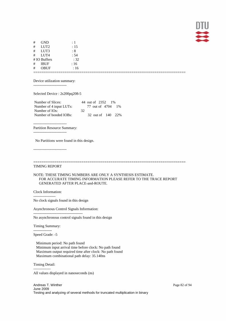
Andreas T. Winther June 2009 Testing and analyzing of several methods for truncated multiplication in binary
Page 82 of 94
# GND : 1 # LUT2 : 15 # LUT3 : 8 # LUT4 : 54 # IO Buffers : 32 # IBUF : 16 # OBUF : 16 ========================================================================= Device utilization summary: --------------------------- Selected Device : 2s200pq208-5 Number of Slices: 44 out of 2352 1% Number of 4 input LUTs: 77 out of 4704 1% Number of IOs: 32 Number of bonded IOBs: 32 out of 140 22% --------------------------- Partition Resource Summary: --------------------------- No Partitions were found in this design. --------------------------- ========================================================================= TIMING REPORT NOTE: THESE TIMING NUMBERS ARE ONLY A SYNTHESIS ESTIMATE. FOR ACCURATE TIMING INFORMATION PLEASE REFER TO THE TRACE REPORT GENERATED AFTER PLACE-and-ROUTE. Clock Information: ------------------ No clock signals found in this design Asynchronous Control Signals Information: ---------------------------------------- No asynchronous control signals found in this design Timing Summary: --------------- Speed Grade: -5 Minimum period: No path found Minimum input arrival time before clock: No path found Maximum output required time after clock: No path found Maximum combinational path delay: 35.140ns Timing Detail: -------------- All values displayed in nanoseconds (ns)

Andreas T. Winther June 2009 Testing and analyzing of several methods for truncated multiplication in binary
Page 83 of 94
========================================================================= Timing constraint: Default path analysis Total number of paths / destination ports: 7864 / 9 ------------------------------------------------------------------------- Delay: 35.140ns (Levels of Logic = 15) Source: a<7> (PAD) Destination: y<15> (PAD) Data Path: a<7> to y<15> Gate Net Cell:in->out fanout Delay Delay Logical Name (Net Name) ---------------------------------------- ------------ IBUF:I->O 16 0.924 2.800 a_7_IBUF (a_7_IBUF) LUT4:I0->O 2 0.653 1.340 stage[1].st/s2.st2[6].sta/cout1 (c<1><6>) LUT4:I2->O 2 0.653 1.340 stage[2].st/s2.st2[6].sta/Mxor_s_xo<1>1 (s<2><6>) LUT4:I3->O 2 0.653 1.340 stage[3].st/s2.st2[5].sta/Mxor_s_xo<1>1 (s<3><5>) LUT4:I3->O 2 0.653 1.340 stage[4].st/s2.st2[4].sta/Mxor_s_xo<1>1 (s<4><4>) LUT4:I3->O 2 0.653 1.340 stage[5].st/s2.st2[3].sta/Mxor_s_xo<1>1 (s<5><3>) LUT4:I3->O 2 0.653 1.340 stage[6].st/s2.st2[2].sta/Mxor_s_xo<1>1 (s<6><2>) LUT4:I3->O 3 0.653 1.480 stage[7].st/s2.st2[1].sta/Mxor_s_xo<1>1 (s<7><1>) LUT4:I2->O 2 0.653 1.340 add/carry_in_internal_2_or00001 (add/carry_in_internal<2>) LUT3:I2->O 2 0.653 1.340 add/carry_in_internal_3_or00001 (add/carry_in_internal<3>) LUT3:I2->O 2 0.653 1.340 add/carry_in_internal_4_or00001 (add/carry_in_internal<4>) LUT3:I2->O 2 0.653 1.340 add/carry_in_internal_5_or00001 (add/carry_in_internal<5>) LUT3:I2->O 2 0.653 1.340 add/carry_in_internal_6_or00001 (add/carry_in_internal<6>) LUT4:I0->O 1 0.653 1.150 add/carry_in_internal_7_or00001 (add/carry_in_internal<7>) OBUF:I->O 5.557 y_15_OBUF (y<15>) ---------------------------------------- Total 35.140ns (14.970ns logic, 20.170ns route) (42.6% logic, 57.4% route) ========================================================================= CPU : 16.33 / 16.73 s | Elapsed : 16.00 / 16.00 s --> Total memory usage is 134544 kilobytes Number of errors : 0 ( 0 filtered) Number of warnings : 40 ( 0 filtered) Number of infos : 0 ( 0 filtered)


![DBPIA-NURIMEDIAacml.gnu.ac.kr/download/Publications/28.pdf39 6 2011. 6 Navier-Stokes Eulerian Eulerian Bourgault [7] 01 FLUENT* FENSAP-ICE 3.1 Truncated Flapped Flapol Truncated Truncated](https://img.dokumen.tips/doc/110x75/6064d2c624aba96be8533943/dbpia-39-6-2011-6-navier-stokes-eulerian-eulerian-bourgault-7-01-fluent-fensap-ice.jpg)