Embed Size (px)
Citation preview

Test station software for traffic safety systems Design and implementation of a software tool framework for testing software modules in traffic safety systems
Master of Science Thesis in Automation and Mechatronics Program
JOHAN AXFORS
Department of Signals and Systems
Division of Automatic Control, Automation and Mechatronics
CHALMERS UNIVERSITY OF TECHNOLOGY
Göteborg, Sweden, 2007
Report No. EX020/2008
1
All rights reserved. This publication is protected by law in accordance with “Lagen om
Upphovsrätt, 1960:729”. No part of this publication may be reproduced, stored in a
retrieval system, or transmitted, in any form or by any means, electronic, mechanical,
photocopying, recording, or otherwise, without the prior permission of the authors.
© Johan Axfors, Göteborg 2008.
2
Abstract Software testing is an important step in the software development process that evaluates the quality of the software. There exist several techniques and methodologies for testing software, but the common purposes of testing software are to reduce risks and find defects in the software.
The project described in this master’s thesis report has been executed at the development department of Sensys Traffic AB.
The goal of this project was to develop a test tool framework for testing software modules in the company’s traffic safety systems. A methodology that can be described as black box testing was used when testing the software modules in the system.
A test tool framework was developed together with a graphical user interface. To evaluate framework two modules were tested. The framework was implemented in C++ and C#.
The test tool framework turned out to be useful immediately since it was developed side by side to the tested software modules.
3
Sammanfattning Mjukvarutestning är ett viktigt steg i mjukvaruutvecklingsprocessen vilket evaluerar kvalitén på mjukvaran. Det finns flera olika tekniker och metoder vid testning av mjukvaror, men de har alla gemensamt att deras mål är att reducera risker och upptäcka defekter i mjukvaror.
Projektet som beskrivs i denna examensarbetsrapport har genomförts på utvecklingsavdelningen på Sensys Traffic AB.
Målet med detta projekt var att utveckla ett ramverk för ett testverktyg för att testa mjukvarumoduler i företagets trafiksäkerhetssystem. En metodologi som kan beskrivas som ”blackbox-testing” användes vid testningen av mjukvarumodulerna i trafiksäkerhetssystemet.
Ett ramverk för ett testverktyg utvecklades tillsammans med ett grafiskt användargränssnitt. För att utvärdera ramverket så testades två moduler i systemet. Ramverket implementerades i C++ och C#.
Ramverket för testverktyget visade sig vara användbart direkt eftersom det utvecklades sida vid sida med de testade mjukvarumodulerna.
4
Acknowledgements This project has been executed as a master’s thesis work with the supervision of Daniel Friman and Lars Westerfur at the development department of Sensys Traffic AB in Jönköping, Sweden.
The implementation part of the project has been supervised and supported by Daniel Friman and the system test philosophy has been supervised and supported by Lars Westerfur, both employees at development department at Sensys Traffic AB.
The development department at Sensys Traffic AB is responsible for development of traffic information and safety systems. About 30 employees in this department are developing both hardware and software for these systems.
I would like to thank all of those who have supported me during the work on this master’s thesis. A special thank you to my supervisors at the development department at Sensys Traffic AB, Daniel Friman, and Lars Westerfur, for all help and valuable ideas which have contributed greatly to the result of the project and helped me to develop my skills as an engineer. I would also like to thank my examiner at Chalmers University of Technology, Knut Åkesson for the support during this master’s thesis work.
The time at Sensys Traffic AB has been a great experience to me and I would like to thank Göran Löfqvist manager of the development department at Sensys Traffic AB for giving me this opportunity. I would also like to thank my parents for giving me accommodation and support in Jönköping during the time of the project.
5
Table of contents
Definitions, acronyms and abbreviations ......................................................................... 7
1. Introduction .............................................................................................................. 8
1.1. Problem statement ............................................................................................ 8
1.2. Project objectives.............................................................................................. 9
1.3. Restrictions ....................................................................................................... 9
1.4. Report outline ................................................................................................... 9
2. Theory..................................................................................................................... 10
2.1. Sensys Traffic AB .......................................................................................... 10
2.2. Sensys’ system................................................................................................ 10
2.2.1. New modular software system ............................................................... 12
2.3. Trends in software development..................................................................... 12
2.3.1. Software development lifecycle ............................................................. 13
2.4. Software requirement specification ................................................................ 13
2.5. Software design specification......................................................................... 14
2.6. Software testing .............................................................................................. 14
2.6.1. Why testing software? ............................................................................ 14
2.6.2. White box testing.................................................................................... 15
2.6.3. Black box testing .................................................................................... 15
2.6.4. Gray box testing ..................................................................................... 16
2.6.5. Unit testing ............................................................................................. 17
2.6.6. Integration testing ................................................................................... 17
2.6.7. Validation testing.................................................................................... 19
2.6.8. System testing......................................................................................... 19
2.6.9. Acceptance testing.................................................................................. 19
2.6.10. Test teams ............................................................................................... 20
2.6.11. Planning software tests ........................................................................... 20
2.7. Object oriented programming languages........................................................ 21
2.7.1. C++......................................................................................................... 22
2.7.2. C# ........................................................................................................... 22
2.8. FTP ................................................................................................................. 23
2.9. CAN................................................................................................................ 23
2.10. XML ........................................................................................................... 23
3. Problem description................................................................................................ 25
4. Project execution .................................................................................................... 26
4.1. Implementation languages and implementation environments ...................... 26
6
4.2. Methodology and planning............................................................................. 26
4.3. Software modules ........................................................................................... 27
4.4. Device manager module ................................................................................. 27
4.5. Log manager module ...................................................................................... 28
4.6. Information transmission................................................................................ 29
4.6.1. Physical connections .............................................................................. 29
4.6.2. Communication between software modules........................................... 30
4.6.3. Remote desktop ...................................................................................... 31
4.6.4. Flexibility ............................................................................................... 32
4.7. Equipment....................................................................................................... 33
4.8. Test approach.................................................................................................. 34
4.8.1. Test of device manager software module ............................................... 34
4.8.2. Test of log manager software module .................................................... 35
4.9. Simulation....................................................................................................... 36
4.10. The implementation.................................................................................... 36
4.10.1. Reusing code .......................................................................................... 36
4.10.2. Structure of implementation ................................................................... 37
4.10.3. XML command parser............................................................................ 39
4.10.4. INI-file reader ......................................................................................... 39
4.10.5. GUI ......................................................................................................... 39
4.10.6. Safe invoker............................................................................................ 40
4.10.7. Main programs........................................................................................ 40
4.10.8. Loggers ................................................................................................... 41
4.10.9. Comparison tests .................................................................................... 41
4.10.10. CAN reply reader................................................................................ 41
4.10.11. Structs ................................................................................................. 41
4.10.12. FTP client wrapper and FTP library................................................... 41
4.10.13. CAN communication.......................................................................... 41
4.10.14. FTP server .......................................................................................... 42
4.10.15. XML reader ........................................................................................ 42
4.10.16. File checker......................................................................................... 42
4.10.17. TCP sockets ........................................................................................ 42
5. Discussion and conclusions .................................................................................... 43
6. Suggestions for future work ................................................................................... 45
7. References. ............................................................................................................. 46
7
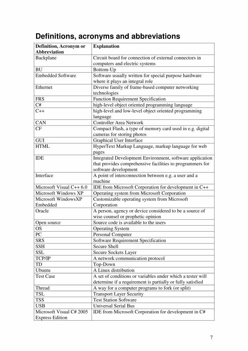
Definitions, acronyms and abbreviations Definition, Acronym or
Abbreviation
Explanation
Backplane Circuit board for connection of external connectors in computers and electric systems
BU Bottom-Up Embedded Software Software usually written for special purpose hardware
where it plays an integral role Ethernet Diverse family of frame-based computer networking
technologies FRS Function Requirement Specification C# high-level object oriented programming language C++ high-level and low-level object oriented programming
language CAN Controller Area Network CF Compact Flash, a type of memory card used in e.g. digital
cameras for storing photos GUI Graphical User Interface HTML HyperText Markup Language, markup language for web
pages IDE Integrated Development Environment, software application
that provides comprehensive facilities to programmers for software development
Interface A point of interconnection between e.g. a user and a machine
Microsoft Visual C++ 6.0 IDE from Microsoft Corporation for development in C++ Microsoft Windows XP Operating system from Microsoft Corporation Microsoft WindowsXP Embedded
Customizable operating system from Microsoft Corporation
Oracle A person, agency or device considered to be a source of wise counsel or prophetic opinion
Open source Source code is available to the users OS Operating System PC Personal Computer SRS Software Requirement Specification SSH Secure Shell SSL Secure Sockets Layer TCP/IP A network communication protocol TD Top-Down Ubuntu A Linux distribution Test Case A set of conditions or variables under which a tester will
determine if a requirement is partially or fully satisfied Thread A way for a computer programs to fork (or split) TSL Transport Layer Security TSS Test Station Software USB Universal Serial Bus Microsoft Visual C# 2005 Express Edition
IDE from Microsoft Corporation for development in C#
8
1. Introduction Software testing is nowadays one of the most important parts of the software development lifecycle. In a competitive market, the quality of the software is essential (Yuyu et al., 2007).
Software testing is an important step in the software development process that evaluates the quality of the software. Historically software testing has not been a prioritized step in this process, but in these days when software has grown in both complexity and size, software testing has been a more crucial part of the software development lifecycle.
There exist several techniques and methodologies for testing software, but they all have in common that their goal is to reduce risk, give feedback and find defects in software (Schaefer, 1997).
When performing software testing the desired result is a level of confidence in the software, confidence in that the software has an acceptable defect rate and that faults are identified before they become failures. Failure is in this case a defining of the behaviour when a software does not act as expected and fail is an error in the software code that may or may not generate a failure when executing the code (Wikipedia – Software testing).
Introducing object oriented programming languages; such as C++ and Java have eased the work of programming of modularised software. Modularising software makes it easier to test smaller parts of the software before integration. To ensure the quality of reusable components software testing is very important to minimize the risk of disseminating bad programming code in various projects (Wu, et al., 2001).
The project described in this master’s thesis report has been executed at the development department of Sensys Traffic AB (henceforth “Sensys” or “the company”) in Jönköping, Sweden.
1.1. Problem statement
The systems developed by Sensys consist of different hardware modules, like sensors, cameras and flash units. To make these hardware modules cooperating as expected, software are running on an industrial PC inside Sensys’ system. In the past the software running on the industrial PC were implemented as one part, which makes it hard to find appearing bugs and other problems with the system. Now this software is undergoing a major reconstruction where the functionality of the software is reimplemented, improved and split up into separate software modules. This work is done because the company wants to achieve the advantages of having modular software running on the systems.
The software in Sensys’ system is often updated to fix bugs and adjust the software to fit the requirements of new costumers and systems. When the software is updated the company employees have to perform time consuming manual tests on the new system to make sure that the new software changes works as expected and that they not have affected any other parts of the software negatively. These software tests are proposed to be done automatically with a new software tool, which is able to test the changed software modules in the system. This project therefore consists of implementing a software tool that is able to make some or all of these tests in a less time consuming and automatically way.
9
1.2. Project objectives
The overall goal with this project is to develop a test tool for testing software modules in Sensys’ systems. This tool is thought to speed up the necessary test procedures that is performed when the software modules in the system is changed. The tool is thought to work as a framework, e.g. if Sensys’ system is extended with more software modules there should be possibilities to add test cases for these modules in the test tool. To simplify the usage of the test tool a graphical user interface (GUI) shall be developed from which a user can control the test tool and get information about the results of the test cases. The test tool should be as automatic as possible to avoid as much of manual work as possible. The test tool shall communicate with Sensys’ system both via Ethernet and CAN. To know if the framework works as expected at least two different software module tests shall be implemented.
The project objectives are in short to:
• Implement communication between Sensys’ system and a standard PC
• Develop a tool framework for testing software modules in Sensys’ system
• Develop a graphical user interface (GUI) for the tool framework
The test tool framework should be implemented in two parts, one part running on a Sensys’ system and one part running on a standard PC beside the system. The software part running on Sensys’ system should be implemented in the programming language C++ and the part running outside Sensys’ system on a standard PC should be implemented in the programming language C#.
1.3. Restrictions
The main part of this project consists of designing and implementing a software. This software is thought to work as a framework that can be extended later. In this project, the focus is to design and get this framework to work and not to perform as many tests cases as possible.
If greater problems come up along the way of developing the test tool framework there are possibilities to limit the scope of this project. It can be done by limit the number of software modules that is tested by the test tool. The modules that are not tested by the tool developed during this project can be implemented later since the tool is going to work as a framework.
1.4. Report outline
In chapter 2 there is given a theoretical background about the concepts used in this project.
In chapter 3 the project problems are presented in its context. This chapter is linking the theory together with the project execution.
Chapter 4 describes the project execution.
In chapter 5 the project is discussed and conclusions are presented.
Chapter 6 gives some suggestions for future work that can be done if extending the project.
10
2. Theory
2.1. Sensys Traffic AB
The project described in this master’s thesis report has been executed at the development department of Sensys Traffic AB (henceforth “Sensys” or “the company”) in Jönköping, Sweden. The company develops and markets various safety systems sold all over the world, not only traffic safety systems. Sensys’ systems could e.g. be found along the Swedish roads were the systems measure the speed of passing vehicles and collect information of vehicles breaking the current speed limit. The most vital part of Sensys’ safety systems is the Doppler radar operating at a 24 GHz frequency. With these radars as starting point, different types of safety systems are built up, both mobile and fixed systems. As mentioned above there are systems detecting vehicles breaking the speed limits, but Sensys also develops systems detecting vehicles running red lights, warning systems for school children road passages or road working places etc. The company also develops systems for detection of broken carbon strips on railway train’s pantographs (mechanical device that collects the electric current from overhead lines for electric trains). Common for most of these systems are beside the radar sensors also advanced digital picture analyzing systems processing still pictures and movies.
The company has around 30 employees, most of them engineers (Sensys Traffic AB).
2.2. Sensys’ system
The Sensys product range consists of a lot of different types of systems, developed and manufactured to meet costumers’ specifications. The intention with this chapter is not to mention all of the systems in detail, but to give an overview of how systems from Sensys can be built up.
The most vital part of the systems from Sensys is the multi-tracking radar sensor mentioned above. This radar makes the systems from Sensys unique on the global the market because of its ability to track vehicles. The radar unit is developed to be as flexible as possible and therefore it can be used in many different applications. The radars are using Doppler technology and works with a frequency at 24 GHz. The radar can monitor several lanes at a deep of over 150 meters and it measures each vehicle in the lobe more than 20 times each second. There are thus no needs for e.g. magnetic sensors or extra equipment under the roads where Sensys’ systems are installed. The radar module communicates in most case with the rest of the system hardware via an industrial PC in the system.
Some of the internal communication between the hardware modules in the systems is done via CAN, Controlled Area Network. This implies that the PC in the system needs to have the abilities to communicate via a CAN bus. A Sensys specific CAN message protocol is used is describing the content of the messages.
Beside the radar unit the systems from Sensys as mentioned above mostly consists of a built-in PC as, a robust industrial PC. This PC is running is running the software needed for linking the hardware modules in the system together and make them work as a system. The PC is running Windows XP Embedded as operating system, a version of Windows XP that is more customizable then the other versions of Windows XP, like the home and professional versions. The operating system is customized by Sensys to suite
11
the current system as good as possible and only the needed parts of the operating system are installed.
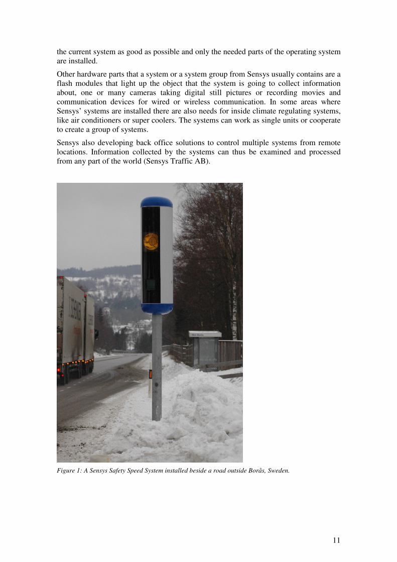
Other hardware parts that a system or a system group from Sensys usually contains are a flash modules that light up the object that the system is going to collect information about, one or many cameras taking digital still pictures or recording movies and communication devices for wired or wireless communication. In some areas where Sensys’ systems are installed there are also needs for inside climate regulating systems, like air conditioners or super coolers. The systems can work as single units or cooperate to create a group of systems.
Sensys also developing back office solutions to control multiple systems from remote locations. Information collected by the systems can thus be examined and processed from any part of the world (Sensys Traffic AB).
Figure 1: A Sensys Safety Speed System installed beside a road outside Borås, Sweden.
12
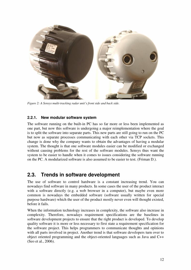
Figure 2: A Sensys multi-tracking radar unit’s front side and back side.
2.2.1. New modular software system
The software running on the built-in PC has so far more or less been implemented as one part, but now this software is undergoing a major reimplementation where the goal is to split the software into separate parts. This new parts are still going to run on the PC but now as separate processes communicating with each other via TCP sockets. This change is done why the company wants to obtain the advantages of having a modular system. The thought is that one software modules easier can be modified or exchanged without causing problems for the rest of the software modules. Sensys thus want the system to be easier to handle when it comes to issues considering the software running on the PC. A modularized software is also assumed to be easier to test. (Friman D.).
2.3. Trends in software development
The use of software to control hardware is a constant increasing trend. You can nowadays find software in many products. In some cases the user of the product interact with a software directly (e.g. a web browser in a computer), but maybe even more common is nowadays the embedded software (software usually written for special purpose hardware) which the user of the product mostly never even will thought existed, before it fails.
When the information technology increases in complexity, the software also increase in complexity. Therefore, nowadays requirement specifications are the baselines in software development projects to ensure that the right product is developed. To develop quality software it is more or less necessary to first state a requirement specification for the software project. This helps programmers to communicate thoughts and opinions with all parts involved in project. Another trend is that software developers turn over to object oriented programming and the object-oriented languages such as Java and C++ (Seo et al., 2006).
13
2.3.1. Software development lifecycle
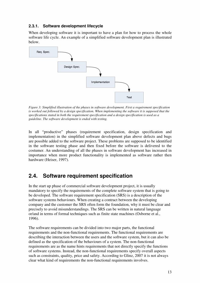
When developing software it is important to have a plan for how to process the whole software life cycle. An example of a simplified software development plan is illustrated below.
Figure 3: Simplified illustration of the phases in software development. First a requirement specification is worked out followed by a design specification. When implementing the software it is supposed that the
specifications stated in both the requirement specification and a design specification is used as a
guideline. The software development is ended with testing.
In all “productive” phases (requirement specification, design specification and implementation) in the simplified software development plan above defects and bugs are possible added to the software project. These problems are supposed to be identified in the software testing phase and then fixed before the software is delivered to the costumer. An understanding of all the phases in software development has increased in importance when more product functionality is implemented as software rather then hardware (Heiser, 1997).
2.4. Software requirement specification
In the start up phase of commercial software development project, it is usually mandatory to specify the requirements of the complete software system that is going to be developed. The software requirement specification (SRS) is a description of the software systems behaviours. When creating a contract between the developing company and the customer the SRS often form the foundation, why it must be clear and precisely to avoid misunderstandings. The SRS can be written in natural language or/and in terms of formal techniques such as finite state machines (Osborne et al., 1996).
The software requirements can be divided into two major parts, the functional requirements and the non-functional requirements. The functional requirements are describing the interaction between the users and the software system, but it can also be defined as the specification of the behaviours of a system. The non-functional requirements are as the name hints requirements that not directly specify the functions of software systems. Instead, the non-functional requirements specify overall aspects such as constraints, quality, price and safety. According to Glinz, 2007 it is not always clear what kind of requirements the non-functional requirements involves.

14
Software requirements must be clear, correct, unambiguous, specific, and verifiable to be useful when performing software testing. The SRS is sometimes used to determine if the results of software test cases are acceptable or not.
2.5. Software design specification
Software design is a process performed before start implementing the software. First the specifications of the software is summarized into documents and then with these documents as starting point the software developers make plans for the software implementation. This step is called software design and the result of this phase is usually summarized into a software design specification document. When planning the design of software, aspects like modularity, compatibility and robustness are usually considered.
The software design specification considers both high- and low-level aspects. This phase of the software development process connects the requirement specification phase with the implementation phase. A proper software design specification can be very helpful when it comes to software testing (Koo S. R. et al., 2004).
2.6. Software testing
Software testing can be described as the process used to measure the quality of developed computer software (Wikipedia – Software testing, 2007). Software testing can be categorized to be functional or structural and static or dynamic.
Static software testing methodology can be described as all software testing approaches where the tested software not is executed. A typical static test can be e.g. reviews, walkthroughs, inspection or symbolic evaluation. The advantages of this kind of test methodologies are that all the code can be inspected regardless of how it actually is going to be used or executed. The performance of the implementation is not considered when using static methodologies and the demand of skills of the testing person is high, which can be a disadvantage when using static software testing methods.
When using dynamic testing methodologies the tested software is executed. There exists several ways of testing a software when it is running, but most of the methods have in common that they are targeting some kind of input-output-relationship, the output generated from a specified input is compared with the requirements (Heiser, 1997). The dynamic testing methodologies are perhaps more easily adopted, why it involves software execution where it is easier to see if something goes wrong.
Functional and structural software testing are described below.
2.6.1. Why testing software?
One of the greatest challenges in software development is to construct quality software. To achieve a high quality level in a software, testing is one of most crucial tasks in the development process. The benefits of testing software are commonly underestimated, despite increased costumer satisfaction and lower maintenance cost when proper software testing has been performed. Significant efforts have been made researching and teaching new test methods on the universities, but the software developing industry
15
has not adopted these new technologies very widely (Juristo et al., 2006). Software testing is a huge field, there exists several different methods, and techniques for testing software but they all have in common that the goal is to improving the quality of the software and ensure that the costumer receive a reliable software (Chen et al., 2004).
When software testing is performed correctly, it can contribute to decrease the number of defects in the targeted software (Freeman, 2002). Individual programmers are only 25% efficient in finding defects in their own software, why software testing is that important in trying to eliminate the rest of the defects (Hesier, 1997).
When it comes to safety-critical software the need of proper testing is obvious. No one wants to fly with an aircraft that risk to crash because of a software failure.
There exist two main approaches when performing software tests, white box testing and black box testing (Seo et al., 2006). These two approaches are described below.
2.6.2. White box testing
White box testing (also known as structural testing, glass box testing and clear box testing) is a software testing method where focus lies on how the software is designed and structured, but the purpose is still to ensure robustness and quality of the software. This test method requires that the tester have both programming skills and knowledge of the internal code that is tested. The tester needs to understand the code to be able to test it with a white box testing approach. These demands on the tester are actually some of the advantages with this testing method, why it forces the tester to use reason when testing the software. White box testing can be performed any time in the development process, but their always need to exist an expected result to determine if the software acts correctly or not (Freeman, 2002).
The steps when performing white box testing can be described as following according to Heiser, 1997:
1. Determine a test strategy or coverage goal (e.g. all statements must be executed at least once, all branches must be executed at least once, all linear code sequences must be executed at least once)
2. Construct test cases to implement the strategy
The disadvantages with white box testing is that if the implemented code is changed the test case also have to be changed and when the number of program paths grown also the test cases grown rapidly.
White box testing is a relatively expensive software testing method and there are always risks that any part of the software code not is tested.
White box testing can be described as an analytic software test method (Freeman, 2002).
2.6.3. Black box testing
Black box testing (also known as functional testing) is a software testing technique where no notice of the software’s internal implementation is taken. When performing black box testing an external perspective of the tested software is taken by the tester. The test designer selects what is both valid input and output data by looking at the requirements of the software. When performing black box there are no need of
16
knowledge of tested software’s internal structure. Black box testing is applicable to all levels of testing (unit, integration, functional, system and acceptance testing) (Freeman, 2002).
In black box testing the software need to be executed why the only thing to examine is the input and the output data to the tested software. Black box testing can therefore be described as a functional testing method, where the function of the software is tested.
There exist many variants of black box testing and they differ in the way that they are applied to the software that is tested (Seo et al., 2006).
The steps when performing black box testing can be described as following according to Heiser, 1997:
1. Identify the functions the software is expected to perform
2. Develop test data to check whether the functions are performed
3. Rely on a oracle to determine the correct response to the test data
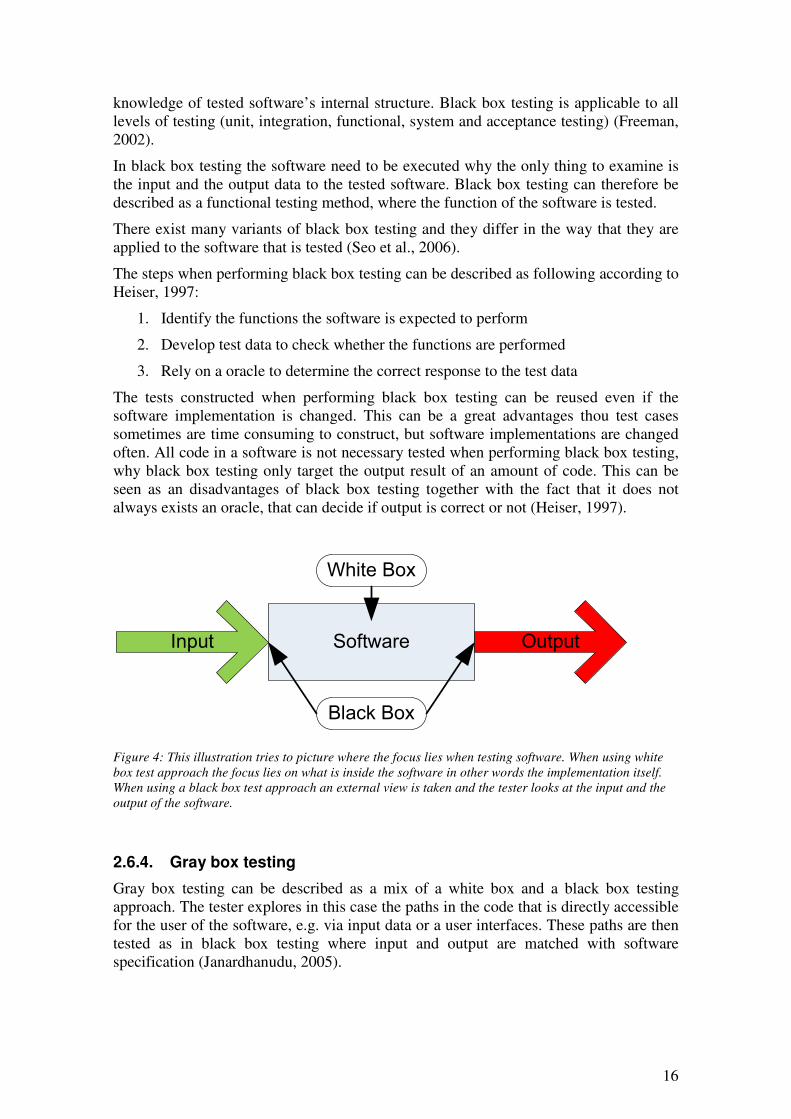
The tests constructed when performing black box testing can be reused even if the software implementation is changed. This can be a great advantages thou test cases sometimes are time consuming to construct, but software implementations are changed often. All code in a software is not necessary tested when performing black box testing, why black box testing only target the output result of an amount of code. This can be seen as an disadvantages of black box testing together with the fact that it does not always exists an oracle, that can decide if output is correct or not (Heiser, 1997).
SoftwareInput Output
Black Box
White Box
Figure 4: This illustration tries to picture where the focus lies when testing software. When using white
box test approach the focus lies on what is inside the software in other words the implementation itself. When using a black box test approach an external view is taken and the tester looks at the input and the
output of the software.
2.6.4. Gray box testing
Gray box testing can be described as a mix of a white box and a black box testing approach. The tester explores in this case the paths in the code that is directly accessible for the user of the software, e.g. via input data or a user interfaces. These paths are then tested as in black box testing where input and output are matched with software specification (Janardhanudu, 2005).
17
2.6.5. Unit testing
Unit testing is a test approach where a basic unit is targeted, e.g. a software module or a software object. The programmer or a programmer team can perform unit testing directly after the module or unit have been implemented. Unit testing can thus work as a fast check that the finished unit is working as expected, when it is not connected and cooperating with other units or software modules. The unit testing can include module interface testing, path testing, exception handling testing, local structure testing and boundary value testing. Unit testing can only find algorithm defects and coding errors in the tested module. Sometimes the tester need to write extra code to be able to run a unit testing case, e.g. simple driving methods that interface and control the tested unit.
Both black box testing and white box testing can be applied when performing unit testing (Wang, 2004).
2.6.6. Integration testing
When performing integration testing the purpose is to verify how a group of software modules work together. Usually a black box testing approach is adopted when performing integration testing. The group of software units is built together and their interfaces are exercised by simulated or real input data. Low-level hardware is simulated in this step to avoid problems that not is connected directly to the software implementation (Wang, 2004). The software design specification or system design document works as the key when deciding if the block of software units work correctly together.
When integrating software units there exists three major strategies, big bang, top-down and bottom-up. The big bang strategy is an approach when all major parts of the software is put together to form the complete software. This integration method can be very effective, but it can also end up in a big mess if all test results not are examined properly (Wikipedia – Integration testing).
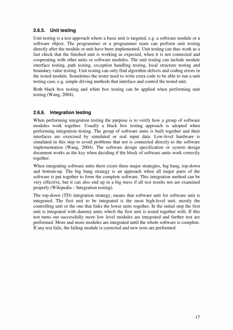
The top-down (TD) integration strategy, means that software unit for software unit is integrated. The first unit to be integrated is the most high-level unit, mostly the controlling unit or the one that links the lower units together. In the initial step the first unit is integrated with dummy units which the first unit is tested together with. If this test turns out successfully more low level modules are integrated and further test are performed. More and more modules are integrated until the whole software is complete. If any test fails, the failing module is corrected and new tests are performed.
18
Module 2
Module 1
Module 4Module 3
Module 5
Module 8
Module 6
Module 7
Module 9 Module 10
Step 1
Step 2
Step 3
Step 4
Figure 5: Illustration of top-down unit integration when performing integration tests. The most high-level modules are integrated in step 1 followed by a test. Next step is to integrate next level of modules with
modules in step 1 followed by new tests. This procedure is repeated until all modules are integrated. If
any failure occurs when testing, the failing module is corrected and new tests are performed.
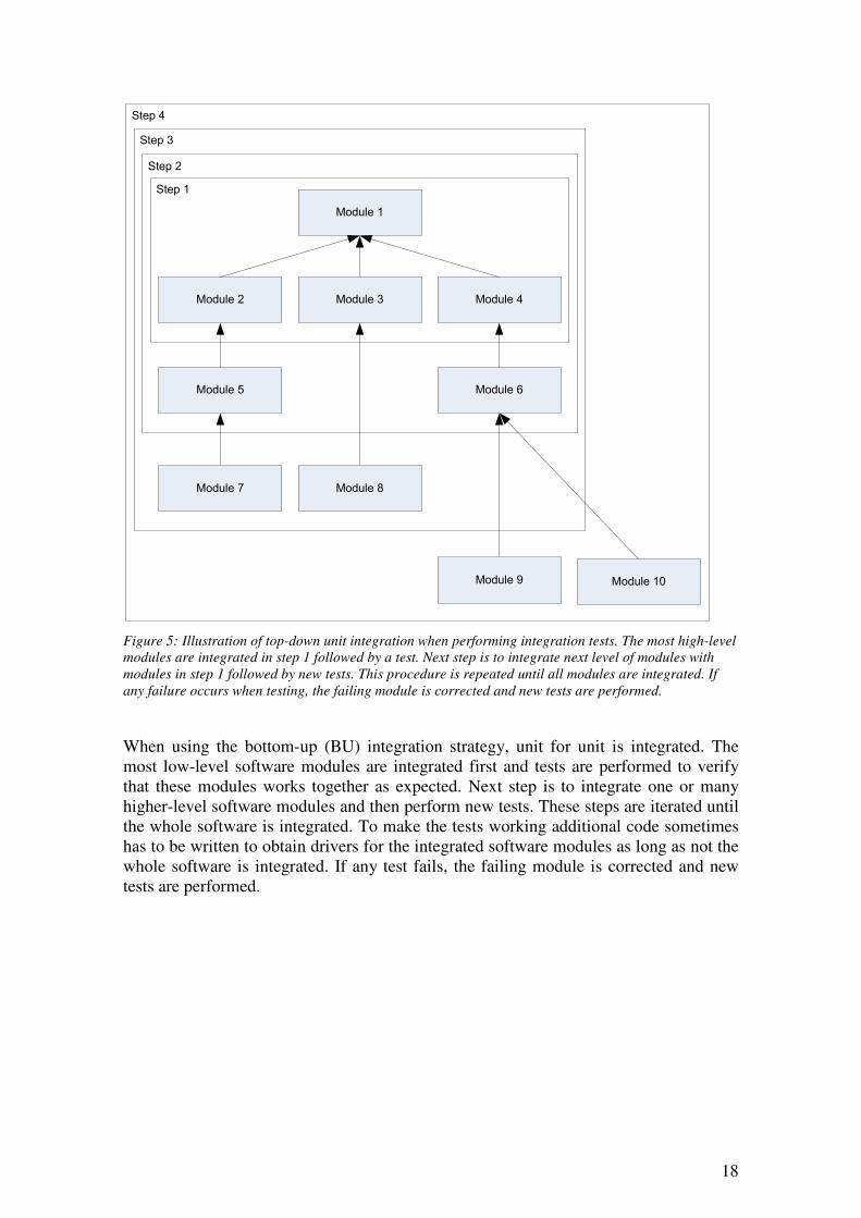
When using the bottom-up (BU) integration strategy, unit for unit is integrated. The most low-level software modules are integrated first and tests are performed to verify that these modules works together as expected. Next step is to integrate one or many higher-level software modules and then perform new tests. These steps are iterated until the whole software is integrated. To make the tests working additional code sometimes has to be written to obtain drivers for the integrated software modules as long as not the whole software is integrated. If any test fails, the failing module is corrected and new tests are performed.
19
Module 2
Module 1
Module 4Module 3
Module 5 Module 6 Module 10
Step 2Step 1
Step 3
Figure 6: Illustration of bottom-up unit integration when performing integration tests. The most low-level
modules are integrated in step 1 and step 2 followed by separate tests. The next step is to integrate the
modules in step 1 and step 2 with higher-level modules followed by new tests. This procedure is repeated
until all modules are integrated. If any failure occurs when testing, the failing module is corrected and
new tests are performed.
The overall goal with integration testing is thus to detect fault in the software design linked to the integration of software modules that already has been tested separately with unit testing methods. It is therefore very important that proper a design document has been worked out before the integration test is started (Wang, 2004).
2.6.7. Validation testing
In the validation testing phase the software is tested with an approach that reveals if the software meets the requirements stated in the SRS. The software is combined together with the hardware it is aimed for to build a complete system. The SRS must thus be well defined whether it should be able to judge the software in the validation tests (Wang, 2004). A validation test checks that the product design satisfies or fits the intended usage, in other word that the right software has been developed. Validation testing usually takes part at the end of a software development process (Tran, 1999).
2.6.8. System testing
System testing is a test procedure performed when the whole software is integrated and evaluated. When performing a system test all the software modules should have been passed the integration test and the complete software should have been integrated with all the hardware and extra software that the software is aimed for. The key for this test is the software requirement specification (SRS), it is thus very important that this specification is well defined and accepted by all involved parts, before any software testing is started. The system testing should be performed in the real environment in where the software later is going to run (Wang, 2004).
2.6.9. Acceptance testing
Acceptance testing (also known as user acceptance testing) is a test that determines if the software is going to be accepted by the costumer or not. There exists acceptance

20
testing strategies where potential costumers are directly involved in this testing phase, as when performing alpha- and beta-testing on software. In these kinds of tests a limited number of potential costumers are given the opportunity to test the software before it is released and give feedback to the developers.
Overall, the acceptance testing can be seen as the final step in a test plan before the software is given to the costumer.
Unit testing
Integration testing
System testing
Acceptance testing
Validation testing
Figure 7: Test plan when testing software. Every step down means that the software is closer to the
release. It is not always necessary perform all the different test steps on a software, depending of the nature of the software itself. If any test fail the software is supposed to be corrected followed by further
tests.
2.6.10. Test teams
When performing software testing it is highly recommended that the company forms teams that drive the test processes. The persons in these test teams must be carefully selected and they should be familiar with technology, business and user requirements. To ensure that the software is tested properly the test team must follow a test plan (Freeman, 2002).
2.6.11. Planning software tests
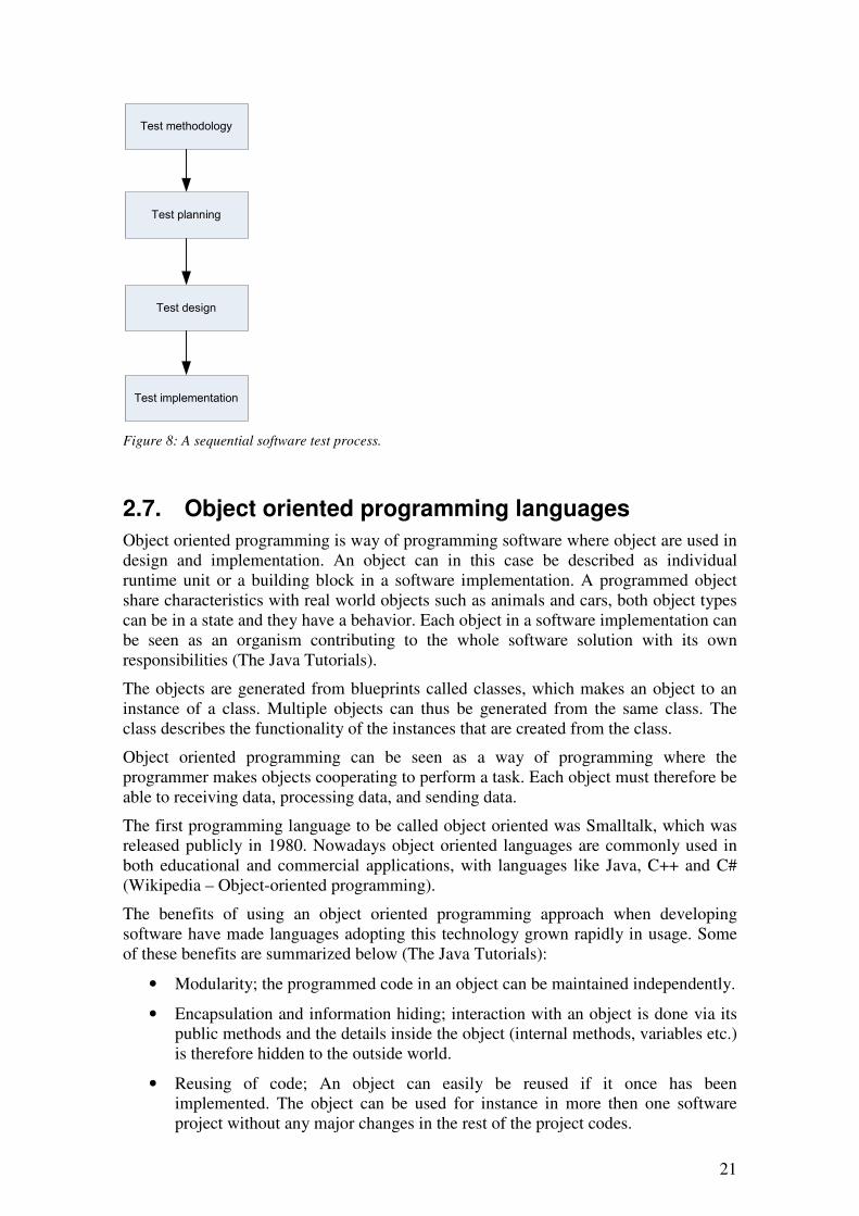
When performing software testing it highly recommended that a structured work model is followed. In the picture below a sequential software test process is described.
21
Test methodology
Test planning
Test design
Test implementation
Figure 8: A sequential software test process.
2.7. Object oriented programming languages
Object oriented programming is way of programming software where object are used in design and implementation. An object can in this case be described as individual runtime unit or a building block in a software implementation. A programmed object share characteristics with real world objects such as animals and cars, both object types can be in a state and they have a behavior. Each object in a software implementation can be seen as an organism contributing to the whole software solution with its own responsibilities (The Java Tutorials).
The objects are generated from blueprints called classes, which makes an object to an instance of a class. Multiple objects can thus be generated from the same class. The class describes the functionality of the instances that are created from the class.
Object oriented programming can be seen as a way of programming where the programmer makes objects cooperating to perform a task. Each object must therefore be able to receiving data, processing data, and sending data.
The first programming language to be called object oriented was Smalltalk, which was released publicly in 1980. Nowadays object oriented languages are commonly used in both educational and commercial applications, with languages like Java, C++ and C# (Wikipedia – Object-oriented programming).
The benefits of using an object oriented programming approach when developing software have made languages adopting this technology grown rapidly in usage. Some of these benefits are summarized below (The Java Tutorials):
• Modularity; the programmed code in an object can be maintained independently.
• Encapsulation and information hiding; interaction with an object is done via its public methods and the details inside the object (internal methods, variables etc.) is therefore hidden to the outside world.
• Reusing of code; An object can easily be reused if it once has been implemented. The object can be used for instance in more then one software project without any major changes in the rest of the project codes.
22
• Debugging; when the code consist of objects the failing part of the code is easier to identify. When the failing object is fixed or a new one is developed, it can be replaced.
There have been criticism against this way of develop software, claiming that object oriented programming not have contributed to improved the productivity and that its limits the programmer. Object oriented programming is however a technique that is commonly used by both commercial and open source programmers all around the world (Wikipedia – Object-oriented programming).
2.7.1. C++
C++ which is pronounced “see plus plus”, is a programming language that has both high-level and low-level capabilities. C++ is one of the most used programming languages in the world. C++ can be seen as a developed version of the programming language C, where the most significant difference is that C++ is object oriented and C is not object oriented. It is probably the portability (ability to use on various platforms) of C++ that has made it to a such common programming language. Old programming code written in C can easily be included in a software project written in C++. The language is a royalty free and a standardized programming language.
C++ is suitable for both programming software for regular and embedded systems (C++ Language Tutorial).
When programming C++ a wide range of tools to ease the coding work is available on the market. The two major commercial IDE:s for developing in C++ is Microsoft Visual C++ and Borland C++ Builder, but beside these there exist many other alternatives both commercial and open source tools.
2.7.2. C#
C# which is pronounced “see sharp”, is a high-level programming language developed by Microsoft Corporation and it is a part of the .NET (dot net) package. The syntax in C# is based on the syntax in C++, but there are even influences from Delphi and Java. When developing C# the focus was to create a programming language that was easy to use and understand.
When programming in C# a garbage collector is helping the programmer to avoid memory leaks (unintentional memory consumption).
Their have been criticism against C# for being resource consuming, it is said that a program implemented in e.g. C++ will have better performance than the same program programmed in C# running on the same hardware.
The .NET package is only fully implemented for Microsoft Windows, so to get all functionality from the language the implementation must be running on a Windows-machine. Derivates for the .NET implementation of C# is on their way but they are yet not fully implemented, partly because parts of the C# libraries are patented by Microsoft. Software implemented in C# are therefore not very easy to port between different platforms and hardware. For embedded systems that usually not are running Microsoft Windows, C# is not a very good choice (Wikipedia – C#).
23
2.8. FTP
FTP or File Transferring Protocol is as the fully name indicates a protocol for transferring data between computers over networks. The protocol is nowadays widely used when it comes to exchanging and manipulating files over TCP/IP based networks. The protocol is not bound to any platform, so a computer running a Linux distribution, such as Ubuntu, can easily exchange files with a server running Microsoft Windows.
Before files can be transferred between two computers, a connection must be established. One of the computer must therefore be running a FTP server software and the other computer a FTP client software. Their exists some different modes in how the connection is established between the client and the server, active mode, passive mode and extended passive mode.
When using standard FTP, data is transferred in clear text, it is not encrypted. This implies that all data that is transferred with this protocol can read by others that the data not is aimed for (even usernames and passwords used when connecting to a FTP-server is sent in clear text). Their exist methods for securing the transfer using SSH (Secure Shell), SSL (Secure Sockets Layer) or TSL (Transport Layer Security).
FTP is a standardized by IETF (Internet Engineering Task Force).
2.9. CAN
Controller Area Network (CAN) was developed by Intel Corporation and Robert Bosch GmbH in early 1980’s for time critical data transfers (Rönnbäck et al., 2004). It was originally developed for use in cars, but soon it started to be used in industrial control systems and embedded networks. CAN is nowadays widely common in a wide field of applications. In 1999 over 50 millions of CAN controllers (CAN connection device) where sold (Obermaisser, 2002).
Devices connected to CAN are usually sensors, actuators or controlling devices. Multiple nodes (units) is connected to each other via a CAN bus. A node (e.g. a sensor) is connected to the bus via a CAN controller device. There is no need for a central unit in when using CAN, why it is a distributed network. The network can operate in bit rates up to 1 MBit/s in a distance of 40 m. If the speed is reduced the distance can be increased.
Each node in a network can receive and transfer data messages, but only one node can send data simultaneously. The CAN message frame has an 8-bits (base format) or 29-bits (extended format) id and up to 8 bytes of data. The message id is up to the user to conform, but e.g. the id can represent a special message id or the id of the sending unit. The bits in a CAN message are sent serially. Messages sent by one node is received by all nodes. CAN has built-in arbitration, messages with highest id is prioritized.
CAN is considered to be a very flexible network solution with good error detection. CAN is therefore well suited for application were safety is highly prioritized (Rönnbäck et al., 2004).
2.10. XML
Extensible Markup Language (XML) is as the name reveals a general markup language. The language is since 1998 recommended by the World Wide Consortium (W3C) and it
24
is a free and open standard. The main purpose of the language is to make it easier to exchange information over platforms and system boundaries. XML is commonly used in applications associated with Internet but the language is also very suitable for other applications when it comes to e.g. encoding documents or serialize data (saving objects to a storage medium).
XML looks very much like HTML, but XML it is not primary aimed for describing web pages, but general data. The tags are not defined like in HTML, the XML-programmers have to make their own tags. This makes XML to a very flexible language when it comes to describing and storing data. XML language is not designed to do anything itself, something that contributes possibilies to use it on multiple platforms and hardware. XML is a structured way of saving data, readable for both computers and human.
The use of XML in various applications has grown rapidly and a large number of software vendors have already adopted the language standard.
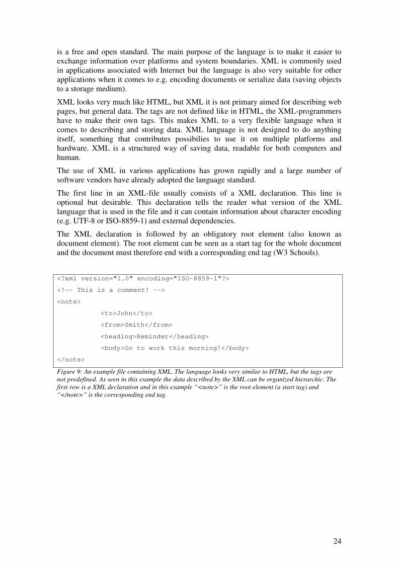
The first line in an XML-file usually consists of a XML declaration. This line is optional but desirable. This declaration tells the reader what version of the XML language that is used in the file and it can contain information about character encoding (e.g. UTF-8 or ISO-8859-1) and external dependencies.
The XML declaration is followed by an obligatory root element (also known as document element). The root element can be seen as a start tag for the whole document and the document must therefore end with a corresponding end tag (W3 Schools).
<?xml version="1.0" encoding="ISO-8859-1"?>
<!—- This is a comment! -->
<note>
<to>John</to>
<from>Smith</from>
<heading>Reminder</heading>
<body>Go to work this morning!</body>
</note>
Figure 9: An example file containing XML. The language looks very similar to HTML, but the tags are
not predefined. As seen in this example the data described by the XML can be organized hierarchic. The
first row is a XML declaration and in this example “<note>” is the root element (a start tag) and
“</note>” is the corresponding end tag.

25
3. Problem description The main purpose with the project stated in this report was to develop a test tool framework that was able to test software modules in Sensys system.
The software in Sensys systems is undergoing a major change, when it is going to be modularized. Beside the work of reconstructing the software the company also wants to test the new software modules to avoid occurrences of software failures. As described in the theory part of this report there exists several methods when it comes to testing software. Every method is necessary not applicable for all testing cases so the choice of test method must be a well considered decision.
The code behind the software running on Sensys system has so far been written in Visual Studio C++ 6.0. This implies that the system probably has to be upgraded with more libraries if code is written in another IDE (an IDE using other libraries) are going to be running on Sensys system. Sensys tries to keep the system as minimalistic as possible when it comes to installing new software at the system. These restrictions are something that has to be considered when implementing the test tool framework. As described in the theory chapter of this report C++ is a commonly used object oriented computer programming language, but there also exist other languages that are well suited for this project.
The industrial PC that the new software modules are going to be running on inside Sensys system has not as good performance as a modern desktop computer. This implies that only the test procedures that really must be running on the system should be running on the system. The test procedures that not have to be running directly on the system should be running on an external PC. The test tool framework will therefore be split into two parts, two parts that have to be able to communicate and exchange data. The system’s internal PC communicates with the system’s hardware modules via CAN and the new software modules running on the internal PC is communicating with each other via TCP sockets. The test tool framework must be able to communicate with the system as it was a part of the tested system. There are also needs of transferring configuration files to the tested system to be able to test the system with different configurations. There exist several different approaches for transferring files between networking computers, but one of them are called FTP and this protocol is described in the theory part of this report.
Exchanging data between different computer systems is not always as easy as it sounds. One standardized way of describing data that can be exchanged over system boundaries is called XML. XML is commonly used at Sensys and the language is well suited for exchanging data between an external PC and the tested system. XML is described in the theory part of this report.
A PC does normally not have the possibility to communicate over a CAN bus (CAN is described in theory part of this report). To be able to communicate with the tested system via CAN the external PC used in the test procedures must be extended with an external device for this purpose and the test tool framework must support this device.
As stated in the initial chapters of this report a graphical user interface is going be developed. There exists several theories of how such interfaces should be designed to ease the usage of software, but since the main purpose of this project is to develop a test tool framework, analyses of these theories is not be prioritized.

26
4. Project execution In this chapter the execution phase of this project is described together with results of the analysis and the decisions that were made. A description of the tested system and the final implementation phase is also given in this chapter.
4.1. Implementation languages and implementation environments
As described in the theory part of this report there exist several different options when it comes to choose a computer programming languages. In this project two different languages were selected for the implementation of the test tool framework.
The part of the TSS that is running on a standard PC was selected to be implemented in C#, in the development environment Microsoft Visual C# 2005 Express which is a free IDE from Microsoft. The choice of this implementation language and the IDE was done in cooperation with software developers at Sensys. The language was chosen mostly because of the good experience of this language from earlier student projects at the company, but also because of it’s easiness to learn and understand. This part of the software was thought to be running on standard PC:s with a normal Microsoft Windows XP operating system installation and therefore it was no problem to install necessary extension files such as the .NET Framework from Microsoft. An implementation in C# won’t work without this extension files. Probably could any other object-oriented language be chosen for the implementation of this part of the software but this language suited well for all parts involved in the project.
The other part of the software that is running on Sensys’ system was selected to be implemented in C++, in the development environment Microsoft Visual C++ 6.0 which is an IDE widely used by the software developers at Sensys. The language was chosen because this is the language that most of the code already running on Sensys’ system is implemented in. The need of extra extensions in the relatively slimmed Microsoft XP Embedded operating system installations was not necessary to run the TSS. The choice of Microsoft Visual C++ 6.0 as IDE was made to make it easier for other software developers at the company to improve the code in the future. Probably could another object-oriented language be chosen to be the implementing language of this part of the software but not necessary without installing extra extensions to the OS, which was possible but not desirable. The OS running on Sensys’ systems is thought to be as slim as possible, that is one of the reasons why the company prefers to not install any additional software package on the systems if it is possible to avoid.
4.2. Methodology and planning
This project initially started with a meeting with the most involved persons from the company. In this meeting the conditions of the project was explained and some information of the software that was going to be tested was given. The scope of the project was decided to primary consist of trying to test two software modules, the device manager module and the log manager module. These two software modules were the ones in the new modular software system that were the most developed at the time of this project’s start up. During this project these modules were also going to be furthered developed, in other words, the test tool framework that was going to be
27
developed in this project was developed in parallel with the software modules that the test tool was going to be test. This implied that these two projects had strong connections, changes in the software modules possibly could affected the test tool framework project directly. These special conditions were something that had to be considered when executing this project.
4.3. Software modules
To be able to plan for the development of a test tool framework for testing the software modules in Sensys’ systems, a survey had to be performed to know which software modules that were going to exist in the new software system and what functionality this modules were going to have. An overview of the modules is given in the figure below.
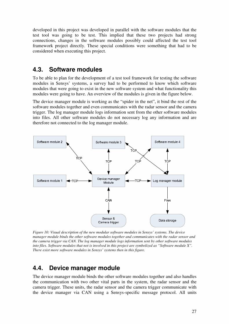
The device manager module is working as the “spider in the net”, it bind the rest of the software modules together and even communicates with the radar sensor and the camera trigger. The log manager module logs information sent from the other software modules into files. All other software modules do not necessary log any information and are therefore not connected to the log manager module.
Figure 10: Visual description of the new modular software modules in Sensys’ systems. The device
manager module binds the other software modules together and communicates with the radar sensor and
the camera trigger via CAN. The log manager module logs information sent by other software modules
into files. Software modules that not is involved in this project are symbolized as “Software module X”.
There exist more software modules in Sensys’ systems then in this figure.
4.4. Device manager module
The device manager module binds the other software modules together and also handles the communication with two other vital parts in the system, the radar sensor and the camera trigger. These units, the radar sensor and the camera trigger communicate with the device manager via CAN using a Sensys-specific message protocol. All units

28
connected with CAN are both able to send and receive messages. The software modules in Sensys’ system communicate via TCP-sockets.
The device manager module also configures the hardware modules in the system, like the radar sensor and the camera trigger. Configuration data is provided to the device manager via XML-files, placed on the system’s storage space. When the device manager is told to configure the system, it reads the data from the XML-files and starts to send messages over CAN to configure the radar sensor and the camera trigger. CAN is used in extended mode, which means that a 29 bits id is used in each CAN message that is sent. Sensys uses the extended mode to be able to use the id bits for both giving the message an address and giving the message a unique message type (the normal mode with 11 bit id is not enough for this purpose). A CAN message can look as in the example below:
1CE0000C | 00 00 09 04 00 00 00 00
id & type data
The first part of the CAN message is an id, in Sensys’ systems it describes both from or to which the message is aimed for and what type of message it is. The second part is message data that is means different things depending of the message type.
4.5. Log manager module
The log manager module is logging information sent from other software modules in Sensys’ systems. It receives the information to log as messages sent over a TCP socket. The modules that are thought to send information to the log manager module therefore have to establish a TCP socket connection to the log manager log module that is implemented as a TCP socket server. The messages are transmitted as a sequence of bytes, split into three parts as in example below:
0C 00 00 00 | 01 00 00 00 | AA BB CC DD
length id data
The first part of the TCP message (0C 00 00 00) tells the receiver how long the sent message is, in example above hexadecimal 0C (decimal 12) bytes. The second part of the TCP message (01 00 00 00) tells the receiver what id the sent message has and therefore how to parse the message, in example above hexadecimal 01 (decimal 1) can e.g. tell the log manager module to log the message data into a file. The third part of the TCP message (AA BB CC DD) is the data that the log manager is supposed to do something with, e.g. log it into a file.
The log manager module is running as a separate process on Sensys’ system’s built-in PC and it supports that more then one other software module is connected for logging. There are also possibilities for a connected TCP socket client to request the log manager module to send back the information in its internal buffer. The buffer consists of latest incoming data.
29
The information that is sent to the log manager module is logged into XML-files, consisting of a XML header, a document root start element and a corresponding end element. The software modules that are using the log manager for logging data are supposed to send their information as complete XML elements.
4.6. Information transmission
When it came to design of the test tool framework it turned out that the company wanted to minimize the usage of resources and capacity on Sensys’ system’s built-in PC. That is why the test tool should affect the system as little as possible when performing tests and why the built-in PC has limited performance. To avoid these limitations it was decided that the test tool framework should be split up into to major software part, one running on Sensys’ system’s built-in PC and one part running on an external standard PC running Windows XP.
It was thus obvious that information had to be exchanged between an external standard PC and the internal PC in Sensys’ system. It turned out that it was possible to connect to Sensys’ system in at least two ways, via an Ethernet-port and via a CAN-port. These two ports could be used for transmitting data between Sensys’ system and an external unit such as a PC.
4.6.1. Physical connections
The Ethernet-port is normally used for connecting a system to a network (LAN, Internet, etc.) but it also possible to connect the system directly to another PC that for instance is running Windows XP. In this case a so called crossover Ethernet cable must be used instead of a regular Ethernet cable (straight-thru Ethernet cable) that is used when connecting a computer network card to e.g. a network switch.
The OS on Sensys’ systems have a built-in feature called remote desktop, that mean that any user that has a computer with a remote desktop client and that is authorized to logon to the system can use the OS on the system from an remote place as long as both are connected to the same network or connected with a crossover Ethernet cable.
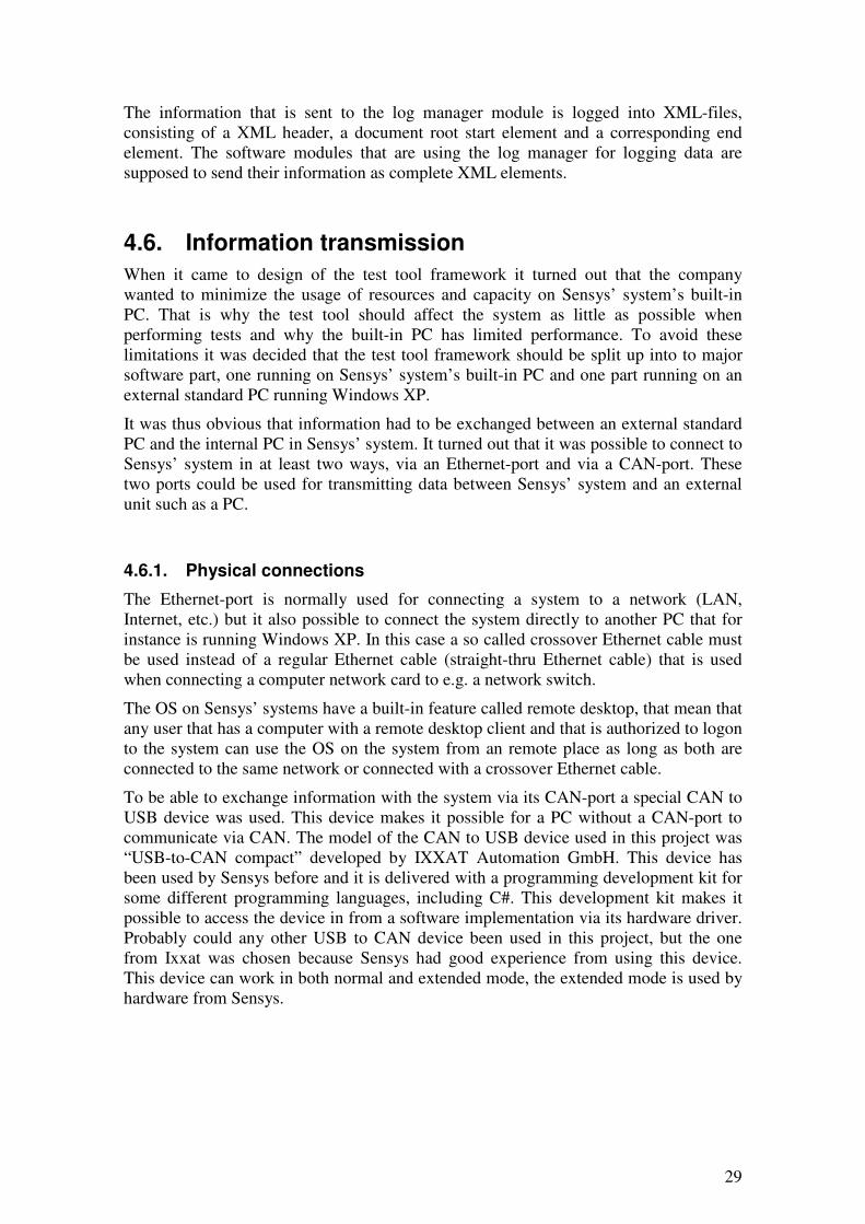
To be able to exchange information with the system via its CAN-port a special CAN to USB device was used. This device makes it possible for a PC without a CAN-port to communicate via CAN. The model of the CAN to USB device used in this project was “USB-to-CAN compact” developed by IXXAT Automation GmbH. This device has been used by Sensys before and it is delivered with a programming development kit for some different programming languages, including C#. This development kit makes it possible to access the device in from a software implementation via its hardware driver. Probably could any other USB to CAN device been used in this project, but the one from Ixxat was chosen because Sensys had good experience from using this device. This device can work in both normal and extended mode, the extended mode is used by hardware from Sensys.
30
Figure 11: With an USB to CAN device it is possible for a regular PC without CAN-port but with a USB-
port to communicate over CAN. The front device where used in this project.
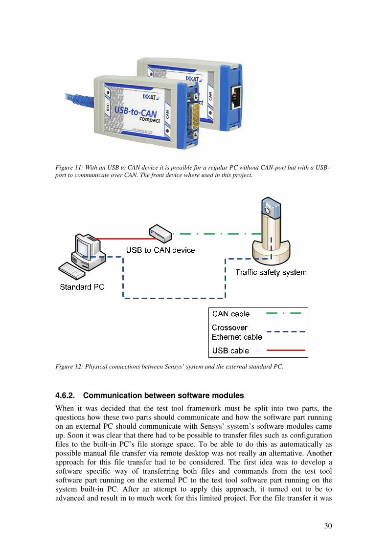
Figure 12: Physical connections between Sensys’ system and the external standard PC.
4.6.2. Communication between software modules
When it was decided that the test tool framework must be split into two parts, the questions how these two parts should communicate and how the software part running on an external PC should communicate with Sensys’ system’s software modules came up. Soon it was clear that there had to be possible to transfer files such as configuration files to the built-in PC’s file storage space. To be able to do this as automatically as possible manual file transfer via remote desktop was not really an alternative. Another approach for this file transfer had to be considered. The first idea was to develop a software specific way of transferring both files and commands from the test tool software part running on the external PC to the test tool software part running on the system built-in PC. After an attempt to apply this approach, it turned out to be to advanced and result in to much work for this limited project. For the file transfer it was
31
instead decided that FTP was going to be used. To make it easy for the user of the test tool framework the tests were going to be initiated and controlled from the external PC, so the FTP server must be implemented on Sensys’ system and the FTP client on the external PC.
The easiest way of collecting and sending CAN communication traffic was to connect to an external CAN bus port on Sensys’ system. This implied that the CAN communication between the system and the test tool framework probably was easiest to implement outside Sensys’ system, thus on the external PC.
The software modules inside Sensys’ system are communicating with each other with messages sent over TCP sockets. This implied that the test tool software also had to be able to communicate this way, to be able to test the software modules separately, e.g. to make the device manager module start configuring a TCP message must be sent to tell the module to start. The two software modules that primarily were going to be tested within this project was implemented as TCP socket servers, thus the test tool framework must be acting as a TCP socket client.
The planned ways of communication is described in figure below.
Device manager
module
Log manager module
Test tool module
Software module 1
Software module 2
Test tool module
File transfer (FTP)
Mess. (TCP) Mess. (TCP)
Mess. (TCP) Mess. (TCP)
Mess. (TCP)
Mess. (TCP)
Traffic safety system
Sensor &
Camera trigger
Mess. (CAN)
Mess. (CAN)
External PC
Mess. (TCP)
Mess. (CAN)
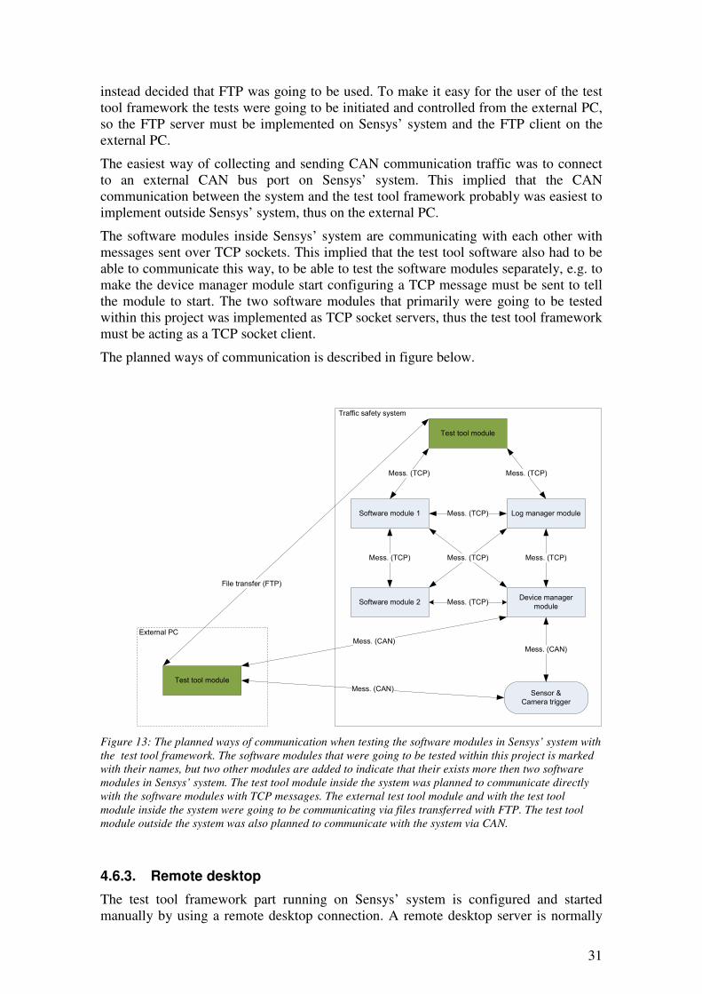
Figure 13: The planned ways of communication when testing the software modules in Sensys’ system with
the test tool framework. The software modules that were going to be tested within this project is marked with their names, but two other modules are added to indicate that their exists more then two software
modules in Sensys’ system. The test tool module inside the system was planned to communicate directly
with the software modules with TCP messages. The external test tool module and with the test tool
module inside the system were going to be communicating via files transferred with FTP. The test tool
module outside the system was also planned to communicate with the system via CAN.
4.6.3. Remote desktop
The test tool framework part running on Sensys’ system is configured and started manually by using a remote desktop connection. A remote desktop server is normally
32
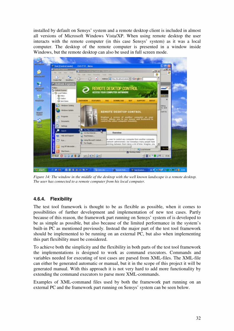
installed by default on Sensys’ system and a remote desktop client is included in almost all versions of Microsoft Windows Vista/XP. When using remote desktop the user interacts with the remote computer (in this case Sensys’ system) as it was a local computer. The desktop of the remote computer is presented in a window inside Windows, but the remote desktop can also be used in full screen mode.
Figure 14: The window in the middle of the desktop with the well known landscape is a remote desktop.
The user has connected to a remote computer from his local computer.
4.6.4. Flexibility
The test tool framework is thought to be as flexible as possible, when it comes to possibilities of further development and implementation of new test cases. Partly because of this reason, the framework part running on Sensys’ system of is developed to be as simple as possible, but also because of the limited performance in the system’s built-in PC as mentioned previously. Instead the major part of the test tool framework should be implemented to be running on an external PC, but also when implementing this part flexibility must be considered.
To achieve both the simplicity and the flexibility in both parts of the test tool framework the implementations is designed to work as command executors. Commands and variables needed for executing of test cases are parsed from XML-files. The XML-file can either be generated automatic or manual, but it in the scope of this project it will be generated manual. With this approach it is not very hard to add more functionality by extending the command executors to parse more XML-commands.
Examples of XML-command files used by both the framework part running on an external PC and the framework part running on Sensys’ system can be seen below.

33
<?xml version="1.0" encoding="UTF-8"?>
<TestStationSoftwareClientCommands Version = "1.0">
<Command ID = "Upload" File = "StartClear.txt"/>
<Command ID = "WaitForFileRemoveOnFtp" File = "StartClear.txt" MaxTime = "20000"/>
<!-- MaxTime in ms -->
<Command ID = "Upload" File = "ServerCommands.xml"/>
<Command ID = "Upload" File = "SystemCfgDecrypted.xml"/>
<Command ID = "Upload" File = "LogTemplate.xml"/>
<Command ID = "Upload" File = "StartParse.txt"/>
<Command ID = "WaitForFileOnFtp" File = "StartLog.txt" MaxTime = "10000"/>
<Command ID = "LogDataFromCan" File = "Canlog.prf" StopLogMessages ="[0x1CE0001B]
[0x10000000]" TimeMessages ="[0x1EE00024]" MaxTime = "120000" CanReplyFile =
"CanReply.list"/> <!-- MaxTime in ms -->
<Command ID = "CompareCanLogFiles" KeyFile = "CanlogKey.prf" InputFile =
"Canlog.prf" SortMessageOnBaseId = "TRUE" NoOfAllowedResends = "3" SpecialMessageIds =
"[0x1FE00000] [0x1FE00001]"/>
<Command ID = "WaitForFileRemoveOnFtp" File = "StartParse.txt" MaxTime = "20000"/>
</TestStationSoftwareClientCommands>
Figure 15: Sample XML-file used by the test tool framework software part running on an external PC.
The type of the command is identified by the argument “ID” and the rest of the arguments are input data
to the methods that are executed when executing the command. Why this part of the test tool framework is
acting as FTP client when transferring XML-command files, this framework part is called
TestStationSoftware Client. TestStationSoftware is the name of the whole test tool framework.
<?xml version="1.0" encoding="UTF-8"?>
<TestStationSoftwareServerCommands Version = "1.0">
<Command ID = "StopProcess" ProcessName = "DeviceManager.exe"/>
<Command ID = "MoveFile" Source = "FtpDir\SystemCfgDecrypted.xml" Dest =
"D:\SystemCfgDecrypted.xml"/>
<Command ID = "MoveFile" Source = "FtpDir\LogTemplate.xml" Dest =
"D:\LogTemplate.xml"/>
<Command ID = "StartProcess" ExeFile = "D:\DeviceManager.exe" ExePath = "D:\"/>
<Command ID = "CopyFile" Source = "StartLog.txt" Dest = "FtpDir\StartLog.txt"/>
<Command ID = "Wait" Time = "5000"/> <!-- Time in ms -->
<Command ID = "SendMessageWithTcp" MessageId = "0x00000000" Data = "" Address =
"localhost" Port = "50003" />
</TestStationSoftwareServerCommands>
Figure 16: Sample XML-file used by the test tool framework software part running on the Sensys’ system
built-in PC. The type of the command is identified on its argument “ID” and the rest of the arguments are
input data to the methods that are executed when executing a command. Why this part of the test tool
framework is acting as FTP server when transferring XML-command files, this framework part is called TestStationSoftware Server. TestStationSoftware is the name of the whole test tool framework.
4.7. Equipment
To ease the development of the test tool framework a complete system from Sensys was not used when executing this project, instead only the necessary hardware parts has been used. From Sensys’ system the built-in industrial PC with its backplane and the radar sensor have been “broken out” from a full system. A standard PC has been used for implementing purpose and for running parts of the test tool framework.
A photo of the hardware configuration used in this project can be seen below.

34
Figure 17: The hardware configuration used when executing this project. In front an Ixxat USB-to-CAN
compact (USB to CAN device), to the left an industrial PC (normally built-in in Sensys’ system) with its backplane (circuit board for connecting external connectors), on top of the industrial PC a radar sensor
and to the right a regular PC (the external PC). (This photo has been taken with a camera that is
commonly used in Sensys’ systems, a Nikon D70s)
4.8. Test approach
When developing the test tool framework, the software modules in Sensys’ system has been seen as black boxes, so the test approach when testing the modules can be characterized as black box testing. An input is sent to the tested module; the output is saved and compared with an expected output.
The two software modules that were tested with the test tool framework within this project were the device manager module and the log manager module.
4.8.1. Test of device manager software module
The first module that was going to be tested was the device manager module. In the test of this module, CAN data is logged into text files until a specified message has arrived or a time out is reached. This log is compared with a log with expected CAN messages, specified by the user.
One of the tests that can be performed with this approach is when the device manager is configuring the radar sensor and the camera trigger. In this case the device manager module reads a configuration from an XML-file. This XML-file describes how the hardware should be configured, thus which messages the device manager module is expected to send and receive. The device manager starts reading and configuring when a command is received via its TCP socket.
35
A comprehensive description of the events when performing a typical device manager module configuring test is listed below. Other similar tests can also be performed by the test tool framework.
1. A configuration XML-file is transferred from the external PC to Sensys’ system via FTP.
2. A start configuration command message is sent from the test tool module inside Sensys’ system to the device manager module via TCP sockets.
3. The device manager module starts sending and receiving messages on the CAN-bus. These messages are logged by the test tool module on the external PC.
4. Logged messages are compared with messages in a key log file and the result of the comparison test is presented to the user in a text file stored on the external PC.
The meaning of this test approach is to determine if the device manager module sends and answers messages correctly in different situations.
4.8.2. Test of log manager software module
The second module that was going to be tested was the log manager module, the module in Sensys’ system that logs incoming TCP message. Besides logging incoming TCP message data the log manager module also keeps an internal log buffer. This internal buffer is used by another software module that is presenting real time log data for a user. Therefore the test tool framework is able to test this module in two ways, with or without stress.
A comprehensive description of the events when performing a log manager log test is listed below.
1. An XML-file consisting of messages to be sent over a TCP socket connection is transferred from the external PC to the tested system via FTP.
2. The message in the XML-file is sent one by one from the test tool module inside Sensys’ system to the log manager module over a TCP socket connection.
3. The log file generated by the log manager module is transferred from Sensys’ system to the external PC via FTP.
4. The log file generated by the log manager module is compared with the XML-file consisting of messages that are sent over the TCP socket connection and the result of the comparison test is presented to the user in a text file stored on the external PC.
A comprehensive description of the events when performing a log manager buffer test is listed below.
1. An XML-file consisting of messages to be sent over a TCP socket connection is transferred from the external PC to the tested system via FTP.
2. The first message in the XML-file is sent from the test tool module inside the Sensys’ system to the log manager module over a TCP socket connection.
36
3. A command is sent from the test tool module inside Sensys’ system to the log manager module over a TCP socket connection, telling the log module to return the content in its internal buffer.
4. The message containing the buffered messages is received and logged to a file by the test tool module inside Sensys’ system.
5. When all messages in the XML-file has been sent and received the log file generated by the test tool module inside Sensys’ system module is transferred from the system to the external PC via FTP.
6. The log generated by the test tool module inside Sensys’ system is compared with the XML-file consisting of messages that are sent over the TCP socket connection and the result of the comparison test is presented to the user in a text file stored on the external PC.
The meanings of the test approaches above are to test the functionality and effectiveness of the log manager module. To be able to test the effectiveness of the module, the time between two TCP messages that are sent to the module is adjustable. This make it possible to determine how many messages per time unit the log manager module are able to log before a failure occurs.
4.9. Simulation
To avoid that hardware related problems occurred when performing tests with the test tool framework it was highly desirable that there should be possibilities to simulate the presence of a radar sensor in the tested system. When testing the software modules possible problems can easier be solved if the behaviour of the radar sensor can be simulated. Not only problems caused by radar misbehaviours is avoided but also provoked hardware errors can be generated to see if the software modules handle these unexpected events correctly.
To simulate the radar sensor in Sensys’ system, its CAN messages must be simulated by the test tool framework. This feature was achieved by letting the external PC, which is connected to the systems CAN-bus with an USB to CAN device, listen to the messages sent on the bus and answer messages that the radar sensor normally was answering.
The part of the test tool framework that handles the simulation of hardware, checks which messages that is sent on the CAN-bus and checks if this CAN-message is listed in a “message-to-answer-list” or not. All CAN-messages to answer is listed together with a corresponding message that is the answer message (the outgoing message from the simulated hardware).
Even other hardware modules, such as the camera trigger can be simulated by adding more messages to the “message-to-answer-list”.
4.10. The implementation
4.10.1. Reusing code
To ease the work of implementing the test tool framework a smaller survey was performed to see if it was possible to reuse programming code from other software projects. It turned out that some of the software modules that were planned to be a part

37
of the test tool framework could be found in Sensys’ source code archive or in open source projects on Internet. These parts of the code could therefore be reused with no or minor changes.
4.10.2. Structure of implementation
When planning for the implementation the goal was to achieve a flexible and general solution that later could be extended with more test cases and modules. Therefore the test tool framework was broken down into smaller parts as in illustration below. The drivers in both parts of the test tool framework are the XML command parsers, which read predefined commands and input data from XML-files written by the user. These XML-files forms together with Sensys’ system’s configuration files so called test libraries. The files in these libraries can be reused, copied and modified to form new test cases.
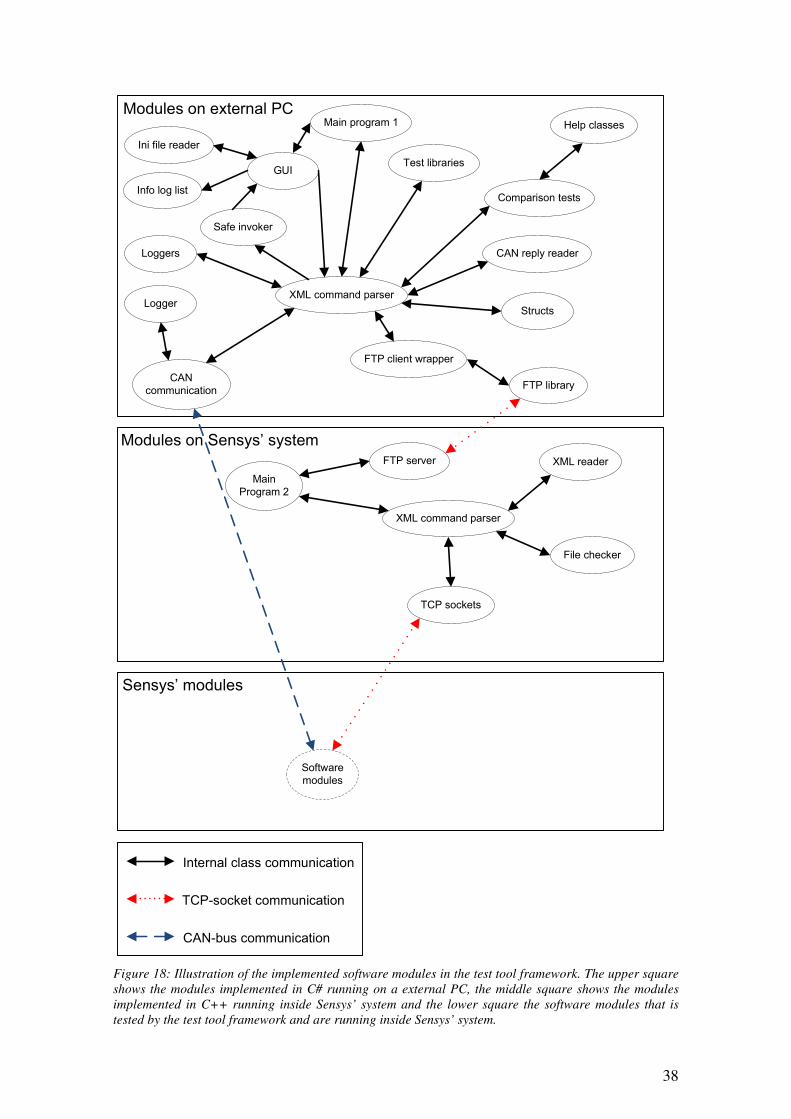
38
GUI
XML command parser
FTP client wrapper
Loggers
CAN
communication
FTP server
Main
Program 2
Test libraries
Software
modules
Internal class communication
TCP-socket communication
CAN-bus communication
XML command parser
Sensys’ modules
Modules on external PC
Comparison tests
Modules on Sensys’ system
Main program 1
TCP sockets
FTP library
Ini file reader
Info log list
Safe invoker
Structs
CAN reply reader
Help classes
Logger
XML reader
File checker
Figure 18: Illustration of the implemented software modules in the test tool framework. The upper square
shows the modules implemented in C# running on a external PC, the middle square shows the modules
implemented in C++ running inside Sensys’ system and the lower square the software modules that is
tested by the test tool framework and are running inside Sensys’ system.
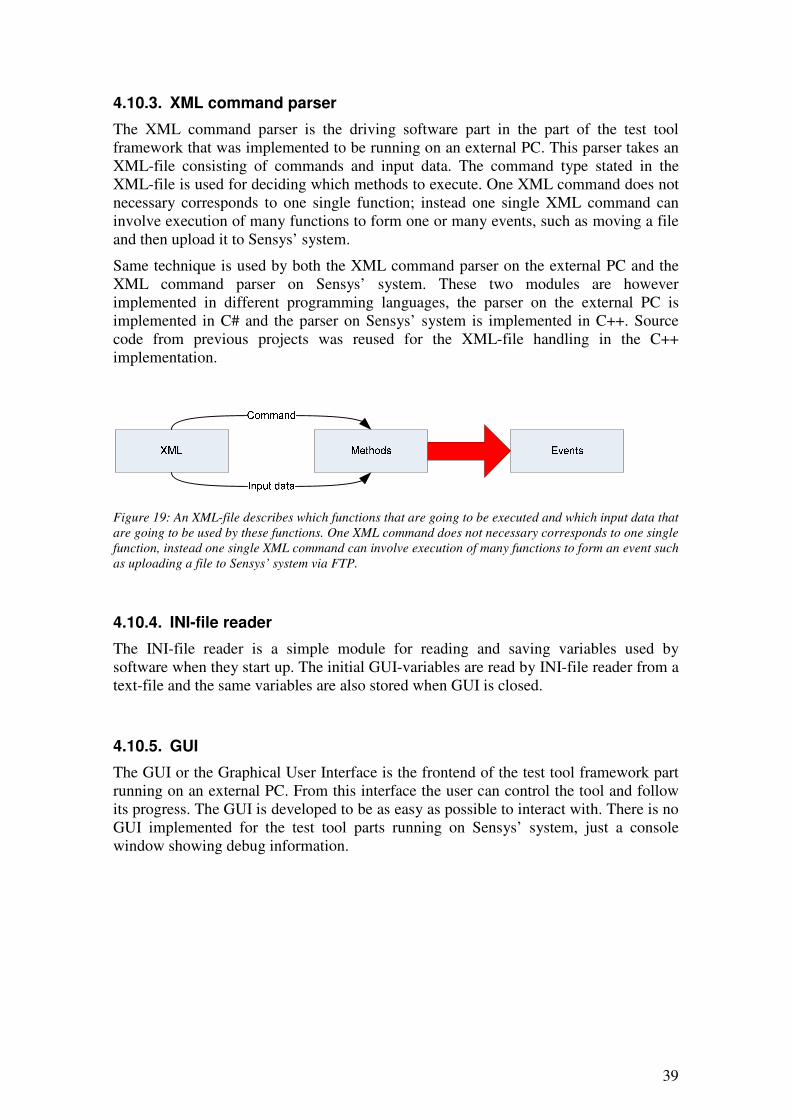
39
4.10.3. XML command parser
The XML command parser is the driving software part in the part of the test tool framework that was implemented to be running on an external PC. This parser takes an XML-file consisting of commands and input data. The command type stated in the XML-file is used for deciding which methods to execute. One XML command does not necessary corresponds to one single function; instead one single XML command can involve execution of many functions to form one or many events, such as moving a file and then upload it to Sensys’ system.
Same technique is used by both the XML command parser on the external PC and the XML command parser on Sensys’ system. These two modules are however implemented in different programming languages, the parser on the external PC is implemented in C# and the parser on Sensys’ system is implemented in C++. Source code from previous projects was reused for the XML-file handling in the C++ implementation.
Figure 19: An XML-file describes which functions that are going to be executed and which input data that
are going to be used by these functions. One XML command does not necessary corresponds to one single
function, instead one single XML command can involve execution of many functions to form an event such
as uploading a file to Sensys’ system via FTP.
4.10.4. INI-file reader
The INI-file reader is a simple module for reading and saving variables used by software when they start up. The initial GUI-variables are read by INI-file reader from a text-file and the same variables are also stored when GUI is closed.
4.10.5. GUI
The GUI or the Graphical User Interface is the frontend of the test tool framework part running on an external PC. From this interface the user can control the tool and follow its progress. The GUI is developed to be as easy as possible to interact with. There is no GUI implemented for the test tool parts running on Sensys’ system, just a console window showing debug information.
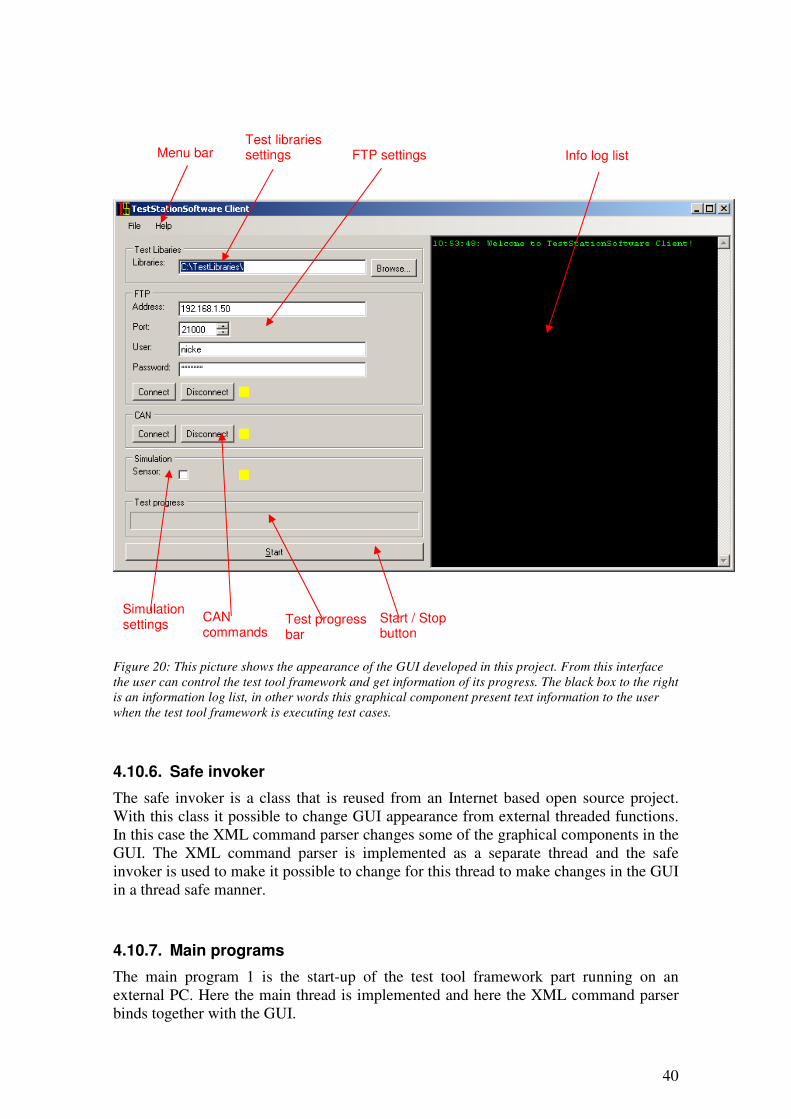
40
Figure 20: This picture shows the appearance of the GUI developed in this project. From this interface
the user can control the test tool framework and get information of its progress. The black box to the right is an information log list, in other words this graphical component present text information to the user
when the test tool framework is executing test cases.
4.10.6. Safe invoker
The safe invoker is a class that is reused from an Internet based open source project. With this class it possible to change GUI appearance from external threaded functions. In this case the XML command parser changes some of the graphical components in the GUI. The XML command parser is implemented as a separate thread and the safe invoker is used to make it possible to change for this thread to make changes in the GUI in a thread safe manner.
4.10.7. Main programs
The main program 1 is the start-up of the test tool framework part running on an external PC. Here the main thread is implemented and here the XML command parser binds together with the GUI.
Menu bar Test libraries settings FTP settings
Simulation settings
CAN commands
Test progress bar
Start / Stop button
Info log list
41
The main program 2 is the part of the implementation on Sensys’ system that contains the main thread. Via the file checker this thread is waiting for incoming files from the FTP server, files that indicates that a test case is started. When all files needed in a test case has arrived the XML command parser is called to start reading XML commands.
4.10.8. Loggers
The logger logs information from the execution of the test tool framework, both data logged from e.g. the CAN-bus and results from the test cases that are executed. The information is logged to text files which easily can be parsed.
4.10.9. Comparison tests
The comparison test classes are performing comparison tests with information logged by the loggers. The results of the comparison tests are logged to text files.
The comparison tests are constructed to be as flexible as possible with possibilities to adjust variables in the comparison commands to lower or higher the requirements of the tests.
The comparison test classes also use some help classes for reading files etc.
4.10.10. CAN reply reader
The CAN reply reader is a class that reads CAN messages from text files. The files that are read consist of lists with messages that are going to be answered by the test tool framework and by which message the test tool is going to answer with.
4.10.11. Structs
In C# a struct can be seen as a programming structure for keeping variables or objects together in a collection that is more easy to handle then free variables. In the implementation of the test tool framework, structs have e.g. been used for the creation of CAN messages.
4.10.12. FTP client wrapper and FTP library
Most of the code in the FTP modules on the external PC has been reused from Internet based open source projects. The FTP library is a static class that is meant to be used with a wrapper that interfaces the rest of the classes. These two classes make it possible for the test tool framework to connect to a FTP server.
4.10.13. CAN communication
The CAN communication is handled via a CAN communication class. The base of this class is reused from a C# example class that is provided together with the CAN to USB device that was used in this project. From this development kit a class was implemented

42
that both could receive and send CAN messages. This class also has the ability to log CAN messages to file with a logger class.
4.10.14. FTP server
This software module is taken from the new modularized software in Sensys’ system, in other words from the collection of software modules that are tested in this project. This module is auto started when the test tool framework is started on Sensys’ system via remote desktop. The FTP server makes it possible for the test tool framework to transfer files from an external PC to Sensys’ system.
4.10.15. XML reader
The XML reader is a XML document reader class implemented in C++. This class was reused from previous projects at the company. With this class it is possible to both read and write XML data.
4.10.16. File checker
The file checker is a help class for checking if a specified file has appeared in a specified directory. In the test tool framework it checks a specified file has been uploaded to the FTP server home directory.
4.10.17. TCP sockets
The TCP socket class can be used for sending and receiving TCP messages. The test cases that are implemented in this project only uses the class for sending TCP messages from the test tool framework to the software modules in Sensys’ system. This class has been reused from another project at Sensys.
43
5. Discussion and conclusions The test tool framework was developed parallel to the software modules that were going to be tested with the framework. This approach is probably not the most common way of performing a software testing project, but it turned out to be a really good way of working. The programmer of the tested software modules received feedback on his work in an early stage of the software development lifecycle. Problems in the tested software that were reveled when developing the test tool framework could be corrected immediately, something that seamed to be appreciated. It is often easier to correct programming code that you have written yourself especially when it is newly implemented.
When developing a test tool framework for the first time it is probably easier to use a black box testing method where it is minimal requirements of knowledge of the inner construction of the software or hardware that are going to be tested. The need of accurate documentation of the expected output from the system is however crucial to be able to develop a successful test tool framework. It is a great advantage to work and cooperate with the developer of the tested object.
When testing software with a black box testing methodology it is probably easier if the software is implemented with a modular design, where the limits between the different parts of the software is well defined. This was the case in this project and even the input/output to the modules were carefully documented, which made the tested software to a good software in the eyes of a tester.
The overall goal with the project stated in this report was i.a. to implement a tool framework for testing software modules in Sensys’ systems. This goal was reached but not all software modules were tested. The intention was not that all modules were going to be tested within this project, but the tool framework is constructed in a way that it can be extended with more tests later. The use of XML-files for controlling the driving parts of the test tool turned out to fit the framework concept very well. By adding more XML commands to the parsers and more executing functions the test tool can be extended to be able to perform other test cases then the one that already are implemented.
With more knowledge and skills in programming the implementation phase of the project had probably been accomplished faster. Instead the whole project became a great opportunity of learning enough to be able to carry out a software developing project.
Some of the software modules and classes in the implementation of the test tool framework were reused from other projects. One of the classes in the test tool that were implemented on Sensys’ system, the FTP server was reused from the software project that was going to be tested with the test tool. When constructing a test tool, reusing code from the software that is tested is maybe a bit bold. The decision of reusing the FTP server code was well-considered and as long as FTP not is the primary target for the tests, this reuse was judged to be ok.
The goal with this project was first of all to implement communication between a standard PC and Sensys’ system. This goal was reached by using standardized protocols, FTP and CAN, and by reusing code from other projects. Before the idea of using FTP came up, an effort was made to implement a special TCP command system. This special system was later discarded before it was fully implemented when it turned out to be a bit to hard to implement for a programming novice. When looking back at
44
this attempt of implementing this kind of functionality it almost seems that it was an attempt to reinvent the wheel.
Another goal with this project was to implement a graphical user interface, GUI, for the test tool framework. The graphical part of the user interface turned out to be easy to construct in Microsoft Visual C# 2005 Express Edition, but it was a bit harder to make the executing parts of the test tool running in separate threads without locking the GUI. By adding the safe invoker class to the code this obstacle was climbed and changes in the GUI appearance could be controlled from the XML command parser class.
Overall the test tool seemed to be useful when testing the new modular software in Sensys’ systems and more tests cases are probably going to be implemented.
45
6. Suggestions for future work This project was executed in form of a master thesis work where the time is limited. Therefore the goal was not to test as many software modules as possible, rather to built up a framework that later can be extended with more test cases. In the scope of this project two software modules where tested, but since Sensys’ systems consists of more modules, an obvious suggestion for feature work is to extend the framework to make it possible to test the remaining software modules. Some of the modules probably need to be tested in more then one way; therefore the test cases will probably exceed the number of software modules in the system.
The XML-files that is parsed as command files by the two software parts in the test tool framework is currently needed to be generated manually. Since XML nowadays is a widely used language, most programming languages has good support for both reading and saving information into XML-files. Another suggestion for future work is thus to develop a new module in the test tool framework that generates command XML-files from an GUI-based form with check boxes, text fields, radio buttons etc.
When developing user interfaces there are several theories of how they should look like, which colors that should be used, where buttons should be placed etc. These rules could probably also be applied when developing GUI in modern software. It is also highly truly that there also exist rules and recommendations that more explicit tells the programmer how to develop a GUI. If the GUI in this test tool framework is reimplemented or changed, theories and rules of these kind could be used to achieve an even more “easy-to-understand” user interface.
Another possibility for future development of the test tool framework could be to make it more intelligent, especially when it comes to come to conclusions of what is wrong when a test case is failing. The test tool framework could e.g. tell the user which the typical reasons are, causing the problem that is detected.
Another idea that popped up during the implementation phase of the project was to port the code that was implemented in C++ to a newer version of Microsoft Visual C++. The new software modules in Sensys’ system are already requiring new upgrades of the operating system, so moving the code to a newer version of Microsoft Visual C++ will not necessary require any extra files in the operating system.
46
7. References. C++ Language Tutorial. <http://www.cplusplus.com/doc/tutorial> (2007-12-14) Chen, T.Y. & Loon, P-L (2004) Experience with teaching black-box testing in a computer science/software engineering curriculum. Education, IEEE Transactions on, Vol. 47 , no 1, 42 – 50. ISSN 0018-9359 Friman, D. (Software Engineer, Sensys Traffic AB, Jönköping), interviews, 2007-2008 Freeman, H. (2002) Software Testing. Instrumentation & Measurement Magazine,
IEEE, Vol. 5, no 3, 48-50. ISSN 1094-6969 Glinz, M. (2007) On Non-Functional Requirements. Requirements Engineering
Conference, 2007. RE '07. 15th IEEE International, Delhi, India, Oct 15-19 2007, pp. 21-26. ISBN 978-0-7695-2935-6 Heiser, J. E. (1997) An overview of software testing. AUTOTESTCON '97. 1997 IEEE
Autotestcon Proceedings, Anaheim, CA, USA, Sep 22-25 1997, pp. 204-211. ISBN 0-7803-4162-7 Ixxat. <http://www.ixxat.de> (2007-12-19) Janardhanudu, G. (2005) White Box Testing. < https://buildsecurityin.us-cert.gov/daisy/bsi/articles/best-practices/white-box/259.html> (2007-12-03) Juristo, N. & Moreno, A.M. (2006) Software Testing Practices in Industry. Software,
IEEE, Vol. 23, no 4, 19-21. ISSN 0740-7459 Koo S. R., Seong P. H. & Cha S. D. (2004) Software design specification and analysis technique for the safety critical software based on programmable logic controller (PLC). High Assurance Systems Engineering, 2004. Proceedings. Eighth IEEE
International Symposium on, pp. 283-284. ISBN 0-7695-2094-4 Obermaisser, R. (2002) CAN emulation in a time-triggered environment. Industrial
Electronics, 2002. ISIE 2002. Proceedings of the 2002 IEEE International, Vol. 1, 270-275. ISBN 0-7803-7369-3 Osborne, M. & MacNish C.K. (1996) Processing natural language software requirement specifications. Requirements Engineering, 1996., Proceedings of the
Second International Conference on, Colorado Springs, CO, USA, Apr 15-18 1996, pp. 229-236. ISBN 0-8186-7252-8 Rönnbäck, S., Hyyppä, K. & Wernersson, Å. (2004) Remote CAN operations in MATLAB over the Internet. Intelligent Systems, 2004. Proceedings. 2004 2nd International IEEE Conference, Vol. 3, 123-128. ISBN 0-7803-8278-1 Schaefer, H. (1997) Tutorial: Organizing, managing and optimizing software testing. Proceedings of the 1997 Asia-Pacific Software Engineering Conference and
International Computer Science Conference, APSEC'97 and ICSC'97, Hong Kong, Hong Kong, Dec 2-5 1997, pp. 532-533

47
Sensys Traffic AB. <http://www.sensystraffic.se> (2007-11-26) Seo, K. I. & Choi, E. M. (2006) Comparison of Five Black-box Testing Methods for Object-Oriented Software. Software Engineering Research, Management and
Applications, Seoul, Korea, Aug 9-11 2006, pp. 213-220. ISBN 0-7695-2656-X The Java Tutorials. <http://java.sun.com/docs/books/tutorial/java/concepts/object.html > (2007-12-13) Tran, E. (1999) Verification/Validation/Certification. http://www.ece.cmu.edu/~koopman/des_s99/verification/index.html (2007-12-10) W3 Schools. <http://www.w3schools.com> (2007-12-13) Wang, L. (2004) Issues on software testing for safety-critical real-time automation systems. Digital Avionics Systems Conference, 2004. DASC 04, Vol. 2, 101-112, ISBN 0-7803-8539-X Wikipedia – C#. <http://en.wikipedia.org/wiki/C_Sharp> (2007-12-14) Wikipedia – Integration testing. <http://en.wikipedia.org/wiki/Integration_testing> (2007-11-26) Wikipedia – Object-oriented programming. < http://en.wikipedia.org/wiki/Object-oriented_programming> (2007-11-26) Wikipedia – Pantograph (rail). <http://en.wikipedia.org/wiki/Pantograph_%28rail%29> (2007-11-26) Wikipedia – Software testing. <http://en.wikipedia.org/wiki/Software_testing> (2007-11-26) Wu, Y., Pan D. & Chen M-H (2001) Techniques for testing component-based software. Proceedings Seventh IEEE International Conference on Engineering of Complex
Computer Systems, Skövde, Sweden, June 11-13 2001, pp. 222-232, ISSN 0-7695-1159-7 Yuyu, Y. & Shen, G. (2007) Research and establishment of quality cost oriented software testing model. 2006 Canadian Conference on Electrical and Computer
Engineering, Ottawa, Ont., Canada, May 7-10 2006, pp. 2410-2415, ISBN 1-4244-0037-6