Embed Size (px)
Citation preview
S.p.A.
TEST AND MEASUREMENT DIVISION
TEST REPORT
RP 2012-0329-00
Page 1 of 32
00 2012-11-05 Formal issue
Rev. Date Description
Results of tests and controls reported in this document refer only to samples as tested and described. It is the responsibility of the manufacturer to ensure that all production models meet the intent of the requirements detailed within this report.
Partial reproductions of this document are absolutely forbidden, except with written authorization by INTEK S.p.A. Cap. Soc. € 1’050’000,00 i.v. – Registry of companies of Brescia, VAT and FC N. IT03268280173 – R.E.A. BS N. 350460
05 10 RP 004 PRE - rev. 02 - RP EMC Eng INTEK S.p.A., Via Mazzini 75, 25086 Rezzato (BS) - I
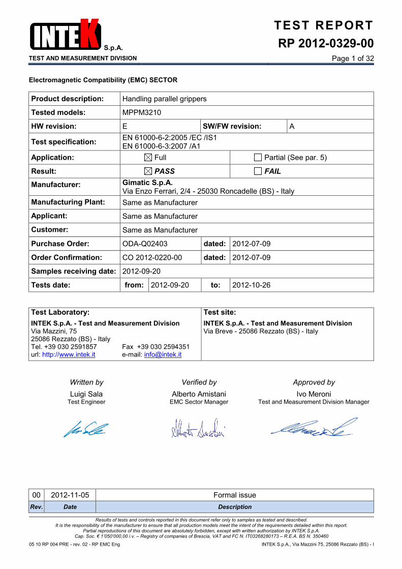
Electromagnetic Compatibility (EMC) SECTOR
Product description: Handling parallel grippers
Tested models: MPPM3210
HW revision: E SW/FW revision: A
Test specification: EN 61000-6-2:2005 /EC /IS1 EN 61000-6-3:2007 /A1
Application: Full Partial (See par. 5)
Result: PASS FAIL
Manufacturer: Gimatic S.p.A. Via Enzo Ferrari, 2/4 - 25030 Roncadelle (BS) - Italy
Manufacturing Plant: Same as Manufacturer
Applicant: Same as Manufacturer
Customer: Same as Manufacturer
Purchase Order: ODA-Q02403 dated: 2012-07-09
Order Confirmation: CO 2012-0220-00 dated: 2012-07-09
Samples receiving date: 2012-09-20
Tests date: from: 2012-09-20 to: 2012-10-26
Test Laboratory: Test site:
INTEK S.p.A. - Test and Measurement Division Via Mazzini, 75 25086 Rezzato (BS) - Italy Tel. +39 030 2591857 Fax +39 030 2594351 url: http://www.intek.it e-mail: [email protected]
INTEK S.p.A. - Test and Measurement Division Via Breve - 25086 Rezzato (BS) - Italy
Written by Verified by Approved by
Luigi Sala Test Engineer
Alberto Amistani EMC Sector Manager
Ivo Meroni Test and Measurement Division Manager
S.p.A.
TEST AND MEASUREMENT DIVISION
TEST REPORT
RP 2012-0329-00
Page 2 of 32
05 10 RP 004 PRE - rev. 02 - RP EMC Eng PARTIAL REPRODUCTION FORBIDDEN INTEK S.p.A., via Mazzini 75, 25086 Rezzato (BS) - I
INDEX
1. PURPOSE ............................................................................................................................................................ 3
2. APPLICABLE DOCUMENTS ............................................................................................................................... 3
2.1 REFERENCE STANDARDS ....................................................................................................................... 3 2.2 BASIC STANDARDS .................................................................................................................................. 3 2.3 OTHERS DOCUMENTS ............................................................................................................................. 4
3. TEST SAMPLE IDENTIFICATION ....................................................................................................................... 5
3.1 DESCRIPTION ............................................................................................................................................ 5 3.2 SAMPLES ORIGIN ...................................................................................................................................... 6 3.3 PORTS DESCRIPTION .............................................................................................................................. 7
4. TEST INFORMATION .......................................................................................................................................... 8
4.1 CONDITIONS DURING THE TESTS .......................................................................................................... 8 4.2 CONFIGURATION MODES ........................................................................................................................ 9 4.3 OPERATION MODES ................................................................................................................................. 9 4.4 PERFORMANCE CRITERIA ..................................................................................................................... 10 4.5 PERFORMANCE EVALUATION METHOD .............................................................................................. 10 4.6 CRITERIA ADOPTED FOR COMPLIANCE EVALUATION ...................................................................... 11
5. TESTS RESULT ................................................................................................................................................ 12
5.1 EMISSION TEST ....................................................................................................................................... 12 5.2 IMMUNITY TEST....................................................................................................................................... 12 5.3 SAMPLES CORRELATION / TEST SEQUENCE ..................................................................................... 13
6. TEST PERFORMED .......................................................................................................................................... 14
6.1 EMISSION ENCLOSURE PORT .............................................................................................................. 14 6.2 RADIO FREQUENCY ELECTROMAGNETIC FIELDS............................................................................. 18 6.3 EMISSION DC POWER PORT ................................................................................................................. 20 6.4 RADIO FREQUENCY COMMON MODE .................................................................................................. 24 6.5 FAST TRANSIENTS ................................................................................................................................. 26 6.6 ELECTROSTATIC DISCHARGES ............................................................................................................ 28 6.7 SURGES ................................................................................................................................................... 30
7. TEST INSTRUMENTATION .............................................................................................................................. 32
8. EUT DOCUMENTATION ................................................................................................................................... 32
9. ANNEXES LIST ................................................................................................................................................. 32
S.p.A.
TEST AND MEASUREMENT DIVISION
TEST REPORT
RP 2012-0329-00
Page 3 of 32
05 10 RP 004 PRE - rev. 02 - RP EMC Eng PARTIAL REPRODUCTION FORBIDDEN INTEK S.p.A., via Mazzini 75, 25086 Rezzato (BS) - I
1. PURPOSE
Purpose of this document is to contain results of the tests performed to verify correspondence of test sample, as identified and described in paragraph 3, to requirements of standards listed in paragraph 2.
2. APPLICABLE DOCUMENTS
In agreement with the manufacturer were been applied the latest EN available edition. In the following of this test report, the “applicable documents” will be indicated without date and/or edition number and/or amendments.
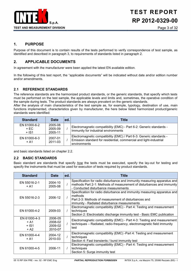
2.1 REFERENCE STANDARDS
The reference standards are the harmonized product standards, or the generic standards, that specify which tests must be performed on the test sample, the applicable levels and limits and, sometimes, the operative condition of the sample during tests. The product standards are always prevalent on the generic standards. After the analysis of main characteristics of the test sample as, for example, typology, destination of use, main functions implemented, characteristics given by manufacturer, the here below listed harmonized product/generic standards were identified:
Standard Date ed. Title
EN 61000-6-2 + EC + IS1
2005-08 2005-09 2005-11
/ Electromagnetic compatibility (EMC) - Part 6-2: Generic standards - Immunity for industrial environments
EN 61000-6-3 + A1
2007-01 2011-03
/ Electromagnetic compatibility (EMC) / Part 6-3: Generic standards - Emission standard for residential, commercial and light-industrial environments
and basic standards listed on chapter 2.2.
2.2 BASIC STANDARDS
Basic standard are standards that specify how the tests must be executed, specify the lay-out for testing and specify the instruments that must be used for execution of tests required by product standards.
Standard Date ed. Title
EN 55016-2-1 + A1
2004-10 2005-08
/ Specification for radio disturbance and immunity measuring apparatus and methods Part 2-1: Methods of measurement of disturbances and immunity - Conducted disturbance measurements
EN 55016-2-3 2006-12 /
Specification for radio disturbance and immunity measuring apparatus and methods Part 2-3: Methods of measurement of disturbances and immunity - Radiated disturbance measurements
EN 61000-4-2 2009-03 / Electromagnetic compatibility (EMC) - Part 4: Testing and measurement techniques Section 2: Electrostatic discharge immunity test - Basic EMC publication
EN 61000-4-3 + A1 + IS1 + A2
2006-05 2008-02 2009-02 2010-07
/ Electromagnetic compatibility (EMC) - Part 4-3: Testing and measurement techniques – Radiated, radio-frequency, electromagnetic field immunity test
EN 61000-4-4 + A1
2004-12 2010-03
/ Electromagnetic compatibility (EMC) -Part 4: Testing and measurement techniques Section 4: Fast transients / burst immunity test
EN 61000-4-5 2006-11 / Electromagnetic compatibility (EMC) - Part 4: Testing and measurement techniques Section 5: Surge immunity test
S.p.A.
TEST AND MEASUREMENT DIVISION
TEST REPORT
RP 2012-0329-00
Page 4 of 32
05 10 RP 004 PRE - rev. 02 - RP EMC Eng PARTIAL REPRODUCTION FORBIDDEN INTEK S.p.A., via Mazzini 75, 25086 Rezzato (BS) - I
Standard Date ed. Title
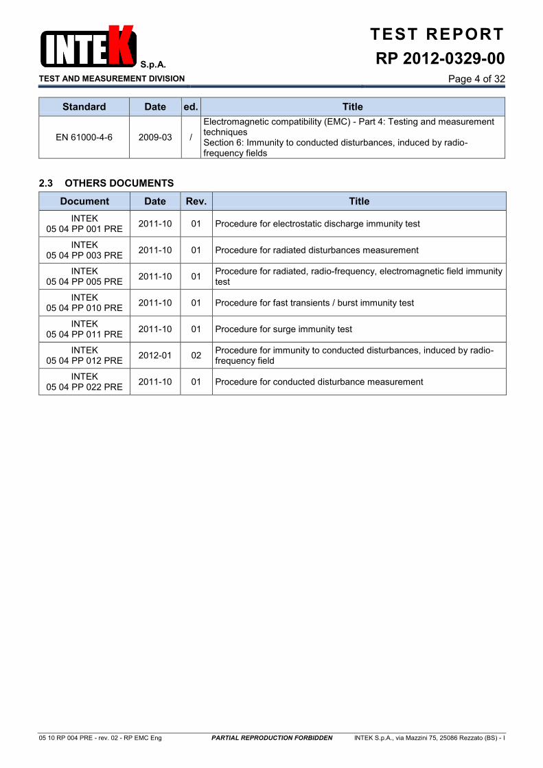
EN 61000-4-6 2009-03 /
Electromagnetic compatibility (EMC) - Part 4: Testing and measurement techniques Section 6: Immunity to conducted disturbances, induced by radio-frequency fields
2.3 OTHERS DOCUMENTS
Document Date Rev. Title
INTEK 05 04 PP 001 PRE
2011-10 01 Procedure for electrostatic discharge immunity test
INTEK 05 04 PP 003 PRE
2011-10 01 Procedure for radiated disturbances measurement
INTEK 05 04 PP 005 PRE
2011-10 01 Procedure for radiated, radio-frequency, electromagnetic field immunity test
INTEK 05 04 PP 010 PRE
2011-10 01 Procedure for fast transients / burst immunity test
INTEK 05 04 PP 011 PRE
2011-10 01 Procedure for surge immunity test
INTEK 05 04 PP 012 PRE
2012-01 02 Procedure for immunity to conducted disturbances, induced by radio-frequency field
INTEK 05 04 PP 022 PRE
2011-10 01 Procedure for conducted disturbance measurement
S.p.A.
TEST AND MEASUREMENT DIVISION
TEST REPORT
RP 2012-0329-00
Page 5 of 32
05 10 RP 004 PRE - rev. 02 - RP EMC Eng PARTIAL REPRODUCTION FORBIDDEN INTEK S.p.A., via Mazzini 75, 25086 Rezzato (BS) - I
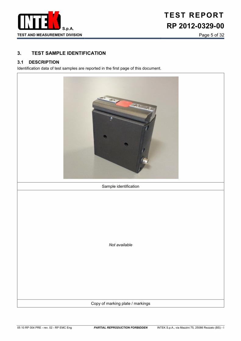
3. TEST SAMPLE IDENTIFICATION
3.1 DESCRIPTION
Identification data of test samples are reported in the first page of this document.
Sample identification
Not available
Copy of marking plate / markings
S.p.A.
TEST AND MEASUREMENT DIVISION
TEST REPORT
RP 2012-0329-00
Page 6 of 32
05 10 RP 004 PRE - rev. 02 - RP EMC Eng PARTIAL REPRODUCTION FORBIDDEN INTEK S.p.A., via Mazzini 75, 25086 Rezzato (BS) - I
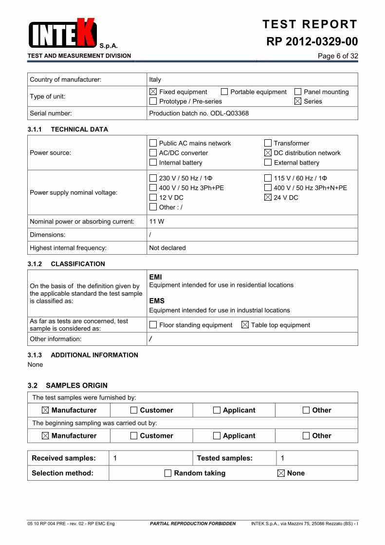
Country of manufacturer: Italy
Type of unit: Fixed equipment Portable equipment Panel mounting
Prototype / Pre-series Series
Serial number: Production batch no. ODL-Q03368
3.1.1 TECHNICAL DATA
Power source:
Public AC mains network Transformer
AC/DC converter DC distribution network
Internal battery External battery
Power supply nominal voltage:
230 V / 50 Hz / 1Φ 115 V / 60 Hz / 1Φ
400 V / 50 Hz 3Ph+PE 400 V / 50 Hz 3Ph+N+PE
12 V DC 24 V DC
Other : /
Nominal power or absorbing current: 11 W
Dimensions: /
Highest internal frequency: Not declared
3.1.2 CLASSIFICATION
On the basis of the definition given by the applicable standard the test sample is classified as:
EMI Equipment intended for use in residential locations
EMS
Equipment intended for use in industrial locations
As far as tests are concerned, test sample is considered as:
Floor standing equipment Table top equipment
Other information: /
3.1.3 ADDITIONAL INFORMATION
None
3.2 SAMPLES ORIGIN
The test samples were furnished by:
Manufacturer Customer Applicant Other
The beginning sampling was carried out by:
Manufacturer Customer Applicant Other
Received samples: 1 Tested samples: 1
Selection method: Random taking None

S.p.A.
TEST AND MEASUREMENT DIVISION
TEST REPORT
RP 2012-0329-00
Page 7 of 32
05 10 RP 004 PRE - rev. 02 - RP EMC Eng PARTIAL REPRODUCTION FORBIDDEN INTEK S.p.A., via Mazzini 75, 25086 Rezzato (BS) - I
3.3 PORTS DESCRIPTION
ID Name Type Max cable length [m]
Cable type Connected
from-to Comment /
Shield connection
01 Enclosure Metal Open
Plastic
02 DC power DC 3 < L < 30 2 wires
Unshielded /
Connected to a DC distribution
03 Control DC 3 < L < 30 1 wire
Unshielded /
Connected to a DC distribution
04 Earth
(Enclosure) FE / N/A
Enclosure to Mechanical chassis
/
Caption:
ID: Number assigned to tested line
Name: Name given by manufacturer
Type: AC = AC Power Port AC mains = AC Mains Power Port DC = DC Power Port N/E = Non-Electrical I/O = Signal Input or Output Port TP = Telecommunication Ports
Comments: For instance type of cable used during tests; 2Pdc: Two lines (positive and negative) 2Pac: Two lines (line and neutral) 3Pdc: Three lines (positive, negative and ground) 3Pac: Three lines (line, neutral and ground) PE: Protection Earth FE: Functional Earth nP: n lines SW: Single wire(s) TW: Twisted pair

S.p.A.
TEST AND MEASUREMENT DIVISION
TEST REPORT
RP 2012-0329-00
Page 8 of 32
05 10 RP 004 PRE - rev. 02 - RP EMC Eng PARTIAL REPRODUCTION FORBIDDEN INTEK S.p.A., via Mazzini 75, 25086 Rezzato (BS) - I
4. TEST INFORMATION
Unless otherwise specified, during the tests the sample/s was/were been configured following the methods and procedure specified in the reference standard.
4.1 CONDITIONS DURING THE TESTS
4.1.1 PERSONNEL PRESENT TO THE TESTS
Test performed by: Luigi Sala (Intek S.p.A.)
Other people present: None
4.1.2 MODIFICATIONS TO SAMPLES
Modifications implemented to test sample are not removed during subsequent tests, if not otherwise specified. In agreement with the manufacturer, the tests performed before the modification were not repeated. Surges: Added a varistor model B72530T250K062 in parallel from dc power supply line.
4.1.3 ENVIRONMENTAL CONDITIONS
Laboratory environmental conditions are recorded during tests and they are shown on relevant chapters. The measurement uncertainties are given with expanded uncertainty with a level of confidence of 95% (k=2)
4.1.4 CONVENTIONS
If applicable, on the right of each chapter or paragraph is written the number of the chapter or paragraph of reference Standard in the form: § number
4.1.5 ABBREVIATIONS
N/A = Not Applicable N/R = Not Required by the customer N/D = Not Declared N/T = Not Tested TR = Test Report EUT = Equipment Under Test ULAB = Laboratory Measurement Uncertainty UCISPR = Instrumentation Measurement Uncertainty EMI = ElectroMagnetic Interference EMS = ElectroMagnetic Susceptibility GRP = Ground Reference Plane AMN = Artificial Mains Network LISN = Line Impedance Stabilization Network ISN = Impedance Stabilization Network VP = Voltage Probe CP = Current Probe CDN = Coupling / Decoupling Network CCC = Capacitive Coupling Clamp
S.p.A.
TEST AND MEASUREMENT DIVISION
TEST REPORT
RP 2012-0329-00
Page 9 of 32
05 10 RP 004 PRE - rev. 02 - RP EMC Eng PARTIAL REPRODUCTION FORBIDDEN INTEK S.p.A., via Mazzini 75, 25086 Rezzato (BS) - I
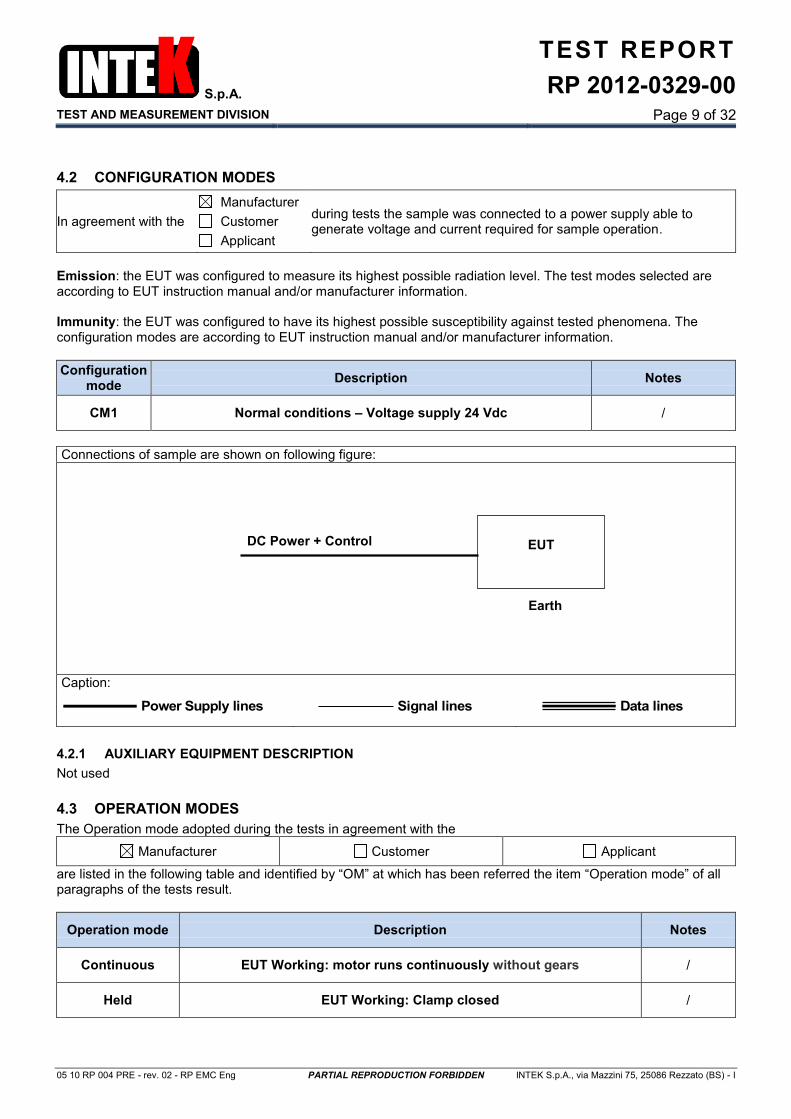
4.2 CONFIGURATION MODES
In agreement with the
Manufacturer
Customer
Applicant
during tests the sample was connected to a power supply able to generate voltage and current required for sample operation.
Emission: the EUT was configured to measure its highest possible radiation level. The test modes selected are according to EUT instruction manual and/or manufacturer information. Immunity: the EUT was configured to have its highest possible susceptibility against tested phenomena. The configuration modes are according to EUT instruction manual and/or manufacturer information.
Configuration mode
Description Notes
CM1 Normal conditions – Voltage supply 24 Vdc /
Connections of sample are shown on following figure:
Caption:
Power Supply lines
Signal lines
Data lines
4.2.1 AUXILIARY EQUIPMENT DESCRIPTION
Not used
4.3 OPERATION MODES
The Operation mode adopted during the tests in agreement with the
Manufacturer Customer Applicant
are listed in the following table and identified by “OM” at which has been referred the item “Operation mode” of all paragraphs of the tests result.
Operation mode Description Notes
Continuous EUT Working: motor runs continuously without gears /
Held EUT Working: Clamp closed /
EUT DC Power + Control
Earth

S.p.A.
TEST AND MEASUREMENT DIVISION
TEST REPORT
RP 2012-0329-00
Page 10 of 32
05 10 RP 004 PRE - rev. 02 - RP EMC Eng PARTIAL REPRODUCTION FORBIDDEN INTEK S.p.A., via Mazzini 75, 25086 Rezzato (BS) - I
4.4 PERFORMANCE CRITERIA
Emission tests: “Quasi peak” emissions, and “average” emissions if any, shall be lower than relevant limits. Measured values are identified on plots as here below described: - Red line: “quasi peak” emission limit - Blue line: “average” emission limit - x [symbol] red: “quasi peak” measured value - + [symbol] blue: “average” measured value Immunity tests: According to requirements of standard EN 61000-6-2, here below reported: “The general principles (performance criteria) for the evaluation of the immunity test results are the following: Performance criterion A: The apparatus shall continue to operate as intended during and after the test. No degradation of performance or loss of function is allowed below a performance level specified by the manufacturer, when the apparatus is used as intended. The performance level may be replaced by a permissible loss of performance. If the minimum performance level or the permissible performance loss is not specified by the manufacturer, either of these may be derived from the product description and documentation and what the user may reasonably expect from the apparatus if used as intended. Performance criterion B: The apparatus shall continue to operate as intended after the test. No degradation of performance or loss of function is allowed below a performance level specified by the manufacturer, when the apparatus is used as intended. The performance level may be replaced by a permissible loss of performance. During the test, degradation of performance is however allowed. No change of actual operating state or stored data is allowed. If the minimum performance level or the permissible performance loss is not specified by the manufacturer, either of these may be derived from the product description and documentation and what the user may reasonably expect from the apparatus if used as intended. Performance criterion C: Temporary loss of function is allowed, provided the function is self-recoverable or can be restored by the operation of the controls.
4.5 PERFORMANCE EVALUATION METHOD
The here above listed performance criteria were applied to the sample by means of the verification the state of clamp.
S.p.A.
TEST AND MEASUREMENT DIVISION
TEST REPORT
RP 2012-0329-00
Page 11 of 32
05 10 RP 004 PRE - rev. 02 - RP EMC Eng PARTIAL REPRODUCTION FORBIDDEN INTEK S.p.A., via Mazzini 75, 25086 Rezzato (BS) - I
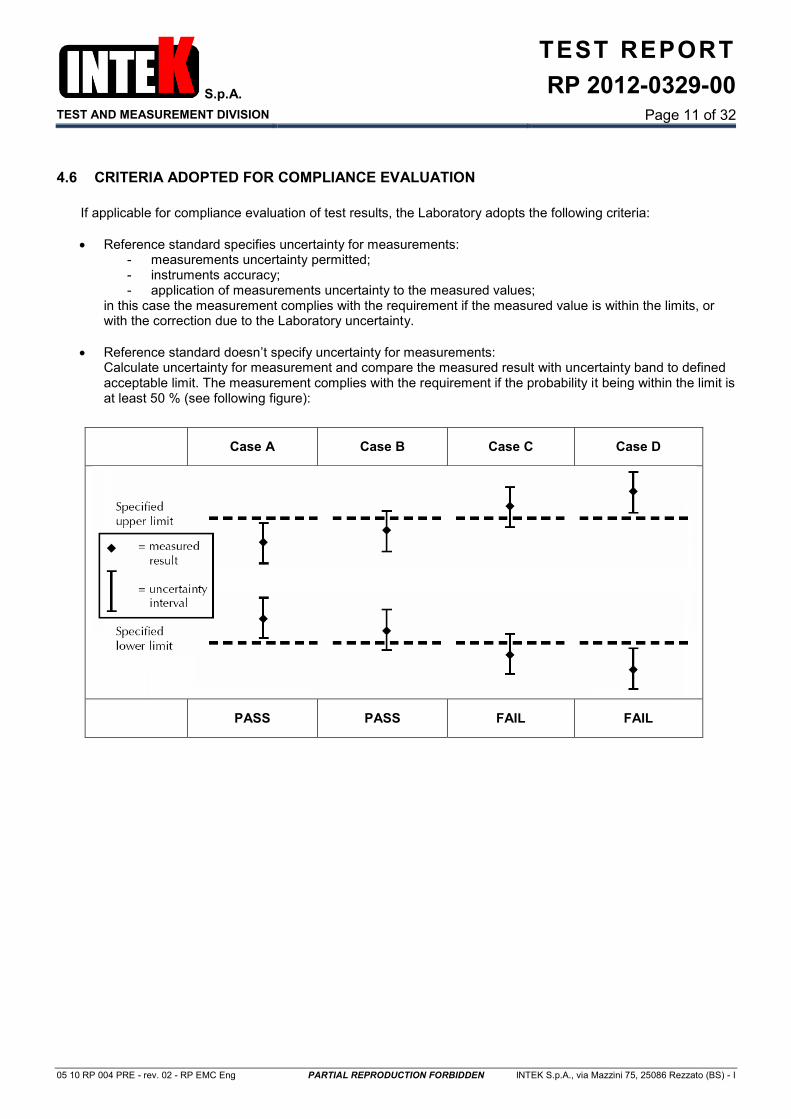
4.6 CRITERIA ADOPTED FOR COMPLIANCE EVALUATION
If applicable for compliance evaluation of test results, the Laboratory adopts the following criteria:
Reference standard specifies uncertainty for measurements: - measurements uncertainty permitted; - instruments accuracy; - application of measurements uncertainty to the measured values;
in this case the measurement complies with the requirement if the measured value is within the limits, or with the correction due to the Laboratory uncertainty.
Reference standard doesn’t specify uncertainty for measurements: Calculate uncertainty for measurement and compare the measured result with uncertainty band to defined acceptable limit. The measurement complies with the requirement if the probability it being within the limit is at least 50 % (see following figure):
Case A Case B Case C Case D
PASS PASS FAIL FAIL

S.p.A.
TEST AND MEASUREMENT DIVISION
TEST REPORT
RP 2012-0329-00
Page 12 of 32
05 10 RP 004 PRE - rev. 02 - RP EMC Eng PARTIAL REPRODUCTION FORBIDDEN INTEK S.p.A., via Mazzini 75, 25086 Rezzato (BS) - I
5. TESTS RESULT
5.1 EMISSION TEST
§ TR Test Reference Result Notes
6.1 Emission enclosure port EN 61000-6-3 Tab 1 PASS /
6.3 Emission DC power port EN 61000-6-3 Tab 1 PASS /
5.2 IMMUNITY TEST
§ TR Test Reference Result Notes
6.6 Electrostatic discharges EN 61000-6-2 Tab 1 PASS /
6.2 Radio frequency
electromagnetic fields EN 61000-6-2 Tab 1 PASS /
6.5 Fast transients EN 61000-6-2 Tab 2 and 3 PASS /
6.4 Radio frequency common mode
EN 61000-6-2 Tab 2 and 3 PASS /
6.7 Surges EN 61000-6-2 Tab 3 PASS #1
Notes: #1 - After modifications described in paragraph 4.1.2.

S.p.A.
TEST AND MEASUREMENT DIVISION
TEST REPORT
RP 2012-0329-00
Page 13 of 32
05 10 RP 004 PRE - rev. 02 - RP EMC Eng PARTIAL REPRODUCTION FORBIDDEN INTEK S.p.A., via Mazzini 75, 25086 Rezzato (BS) - I
5.3 SAMPLES CORRELATION / TEST SEQUENCE
The sample was sequentially subjected to the tests described in the following table:
N. Test Note
1 Radio frequency electromagnetic fields /
2 Radio frequency common mode /
3 Fast transients /
4 Electrostatic discharges /
5 Emission enclosure port /
6 Emission DC power port /
7 Surges /

S.p.A.
TEST AND MEASUREMENT DIVISION
TEST REPORT
RP 2012-0329-00
Page 14 of 32
05 10 RP 004 PRE - rev. 02 - RP EMC Eng PARTIAL REPRODUCTION FORBIDDEN INTEK S.p.A., via Mazzini 75, 25086 Rezzato (BS) - I
6. TEST PERFORMED
6.1 EMISSION ENCLOSURE PORT
Test was performed according to requirements of standards listed on chapter 2. The test method is compliant to requirements of the standard:
EN 55016-2-3
The test is performed following the procedure:
INTEK 05 04 PP 003 PRE
6.1.1 TEST SET-UP
Test site: Fully anechoic room (FAR) - Room N. 26
Antenna height above the floor: 169 cm (half height of anechoic room)
Distance from the point of antenna to the EUT: 3 m
Antenna polarity: Horizontal and vertical
6.1.2 TEST PARAMETERS
Preliminary scan: 0° to 180° (45° step) with peak detector
Final measurement: 0° to 315° (45° step) with quasi peak detector
Frequency measurement range: 30 ÷ 1000 MHz
Limits: See graphics
6.1.3 ENVIRONMENTAL CONDITIONS
Temperature: 24 °C ± 2 °C Relative humidity:
50 % ± 5 % Atmospheric pressure:
1000 mBar ± 20 mBar
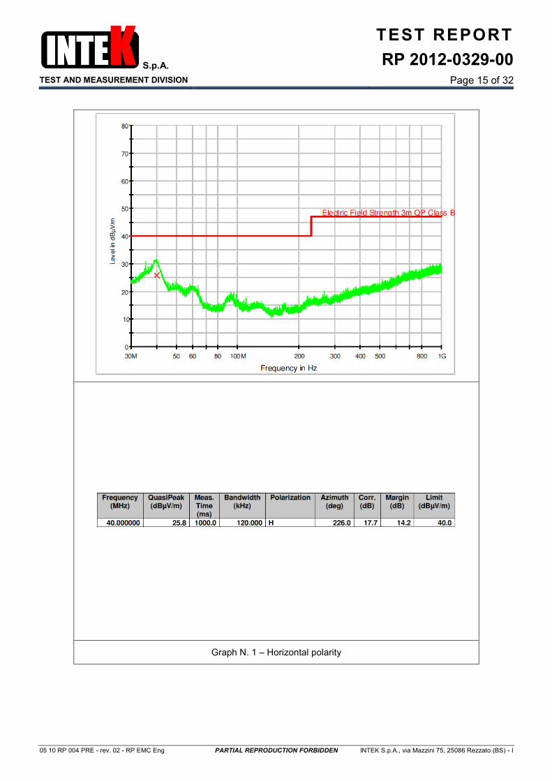
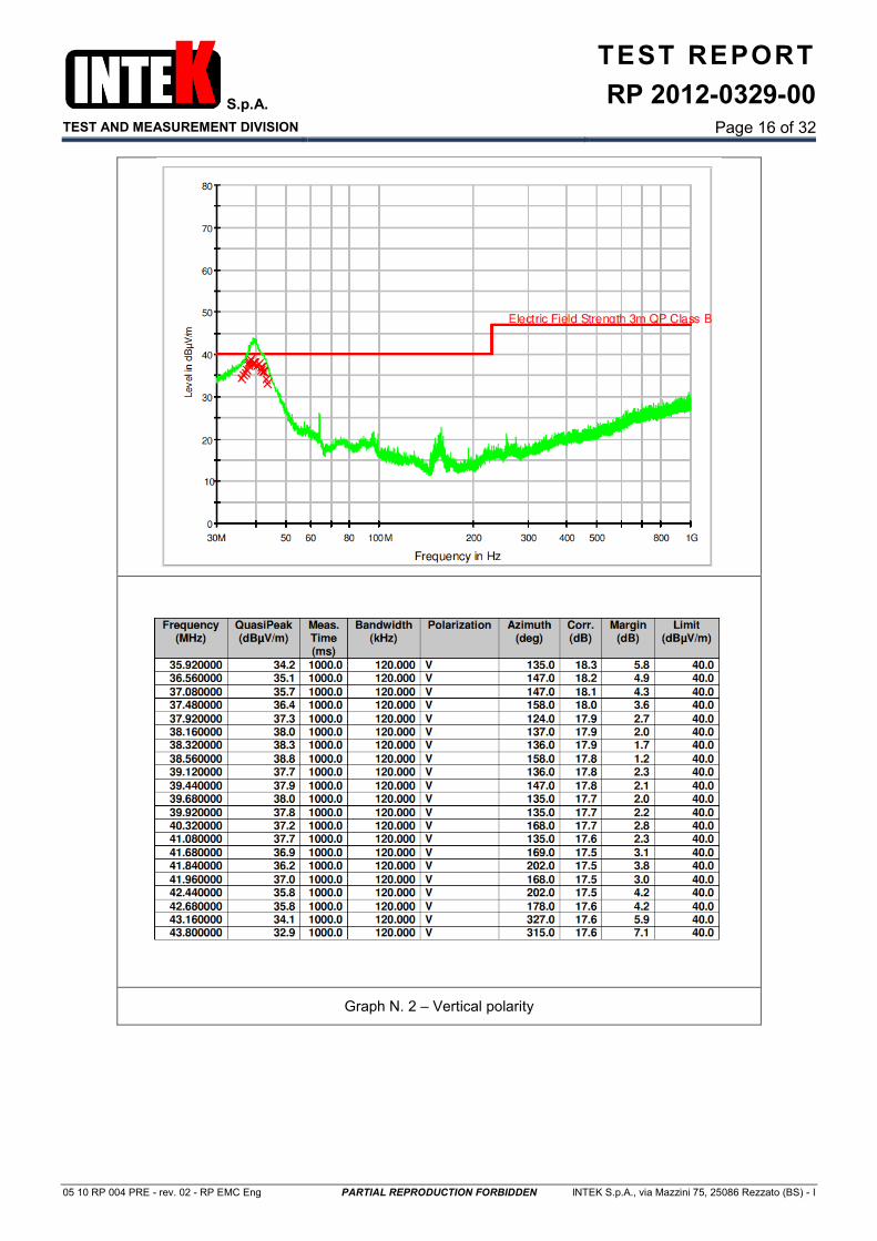
6.1.4 SUMMARY OF RESULTS
Configuration mode: CM1
Graph N. Port under test Polarity Operative mode
(#1) Result Notes
1 Enclosure Horizontal Continuous PASS /
2 Enclosure Vertical Continuous PASS /
Notes: #1 - Operation mode as described in paragraph 4.3
S.p.A.
TEST AND MEASUREMENT DIVISION
TEST REPORT
RP 2012-0329-00
Page 15 of 32
05 10 RP 004 PRE - rev. 02 - RP EMC Eng PARTIAL REPRODUCTION FORBIDDEN INTEK S.p.A., via Mazzini 75, 25086 Rezzato (BS) - I
Graph N. 1 – Horizontal polarity
S.p.A.
TEST AND MEASUREMENT DIVISION
TEST REPORT
RP 2012-0329-00
Page 16 of 32
05 10 RP 004 PRE - rev. 02 - RP EMC Eng PARTIAL REPRODUCTION FORBIDDEN INTEK S.p.A., via Mazzini 75, 25086 Rezzato (BS) - I
Graph N. 2 – Vertical polarity

S.p.A.
TEST AND MEASUREMENT DIVISION
TEST REPORT
RP 2012-0329-00
Page 17 of 32
05 10 RP 004 PRE - rev. 02 - RP EMC Eng PARTIAL REPRODUCTION FORBIDDEN INTEK S.p.A., via Mazzini 75, 25086 Rezzato (BS) - I
Test set-up
6.1.5 TEST INSTRUMENTATION
Description Manufacturer Model Intek ID Last
Calibration Calibration
due
EMI Receiver Rohde & Schwarz ESU26 0692 P 2012-01 2013-01
Bilog-periodic antenna Antenna Research Ass. LPB-2513 0308 P 2010-05 2013-05
Measurement Software Rohde & Schwarz EMC32 PLUS 0686 SW / /
Full Anechoic Chamber SIDT Europe / 0309 P / /
Turntable HD DS 415 0302 P / /
Thermometer / hygrometer Filotecnica Salmoiraghi 1750-2/QM 0222 P 2012-01 2014-01
Barometer Fischer / 0224 P 2010-11 2014-11
6.1.6 TEST MEASUREMENTS UNCERTAINTY
Values of expanded uncertainty are given with a level of confidence of 95 % (k = 2): - ULAB = 2,68 dB except for the frequency range from 410 MHz to 450 MHz where ULAB = 4,33 dB, and ULAB < UCISPR = 5,3 dB (measurement instrumentation uncertainty) in according to standards CISPR 16-4-1 and CISPR 16-4-2.
S.p.A.
TEST AND MEASUREMENT DIVISION
TEST REPORT
RP 2012-0329-00
Page 18 of 32
05 10 RP 004 PRE - rev. 02 - RP EMC Eng PARTIAL REPRODUCTION FORBIDDEN INTEK S.p.A., via Mazzini 75, 25086 Rezzato (BS) - I
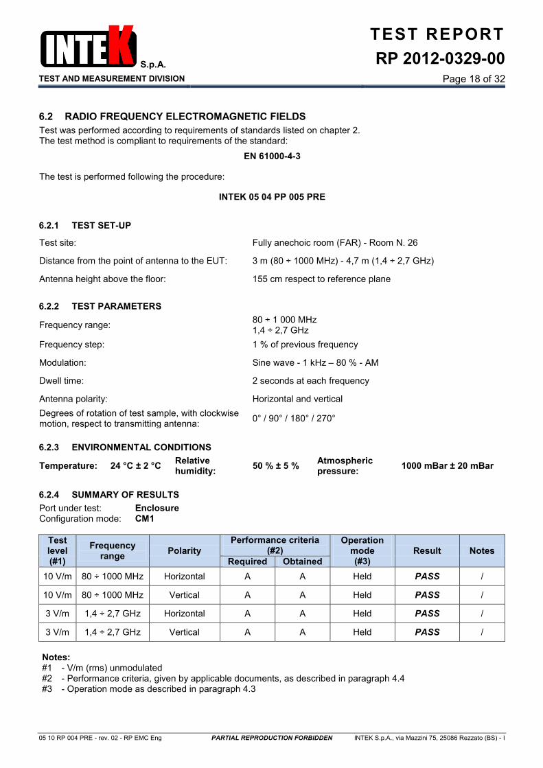
6.2 RADIO FREQUENCY ELECTROMAGNETIC FIELDS
Test was performed according to requirements of standards listed on chapter 2. The test method is compliant to requirements of the standard:
EN 61000-4-3
The test is performed following the procedure:
INTEK 05 04 PP 005 PRE
6.2.1 TEST SET-UP
Test site: Fully anechoic room (FAR) - Room N. 26
Distance from the point of antenna to the EUT: 3 m (80 ÷ 1000 MHz) - 4,7 m (1,4 ÷ 2,7 GHz)
Antenna height above the floor: 155 cm respect to reference plane
6.2.2 TEST PARAMETERS
Frequency range: 80 ÷ 1 000 MHz 1,4 ÷ 2,7 GHz
Frequency step: 1 % of previous frequency
Modulation: Sine wave - 1 kHz – 80 % - AM
Dwell time: 2 seconds at each frequency
Antenna polarity: Horizontal and vertical
Degrees of rotation of test sample, with clockwise motion, respect to transmitting antenna:
0° / 90° / 180° / 270°
6.2.3 ENVIRONMENTAL CONDITIONS
Temperature: 24 °C ± 2 °C Relative humidity:
50 % ± 5 % Atmospheric pressure:
1000 mBar ± 20 mBar
6.2.4 SUMMARY OF RESULTS
Port under test: Enclosure Configuration mode: CM1
Test level (#1)
Frequency range
Polarity
Performance criteria (#2)
Operation mode (#3)
Result Notes
Required Obtained
10 V/m 80 ÷ 1000 MHz Horizontal A A Held PASS /
10 V/m 80 ÷ 1000 MHz Vertical A A Held PASS /
3 V/m 1,4 ÷ 2,7 GHz Horizontal A A Held PASS /
3 V/m 1,4 ÷ 2,7 GHz Vertical A A Held PASS /
Notes: #1 - V/m (rms) unmodulated #2 - Performance criteria, given by applicable documents, as described in paragraph 4.4 #3 - Operation mode as described in paragraph 4.3
S.p.A.
TEST AND MEASUREMENT DIVISION
TEST REPORT
RP 2012-0329-00
Page 19 of 32
05 10 RP 004 PRE - rev. 02 - RP EMC Eng PARTIAL REPRODUCTION FORBIDDEN INTEK S.p.A., via Mazzini 75, 25086 Rezzato (BS) - I
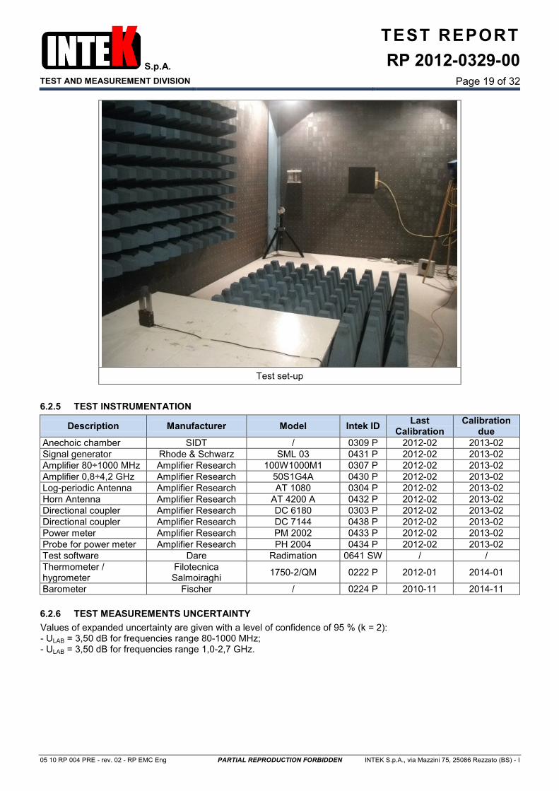
Test set-up
6.2.5 TEST INSTRUMENTATION
Description Manufacturer Model Intek ID Last
Calibration Calibration
due
Anechoic chamber SIDT / 0309 P 2012-02 2013-02
Signal generator Rhode & Schwarz SML 03 0431 P 2012-02 2013-02
Amplifier 80÷1000 MHz Amplifier Research 100W1000M1 0307 P 2012-02 2013-02
Amplifier 0,8÷4,2 GHz Amplifier Research 50S1G4A 0430 P 2012-02 2013-02
Log-periodic Antenna Amplifier Research AT 1080 0304 P 2012-02 2013-02
Horn Antenna Amplifier Research AT 4200 A 0432 P 2012-02 2013-02
Directional coupler Amplifier Research DC 6180 0303 P 2012-02 2013-02
Directional coupler Amplifier Research DC 7144 0438 P 2012-02 2013-02
Power meter Amplifier Research PM 2002 0433 P 2012-02 2013-02
Probe for power meter Amplifier Research PH 2004 0434 P 2012-02 2013-02
Test software Dare Radimation 0641 SW / /
Thermometer / hygrometer
Filotecnica Salmoiraghi
1750-2/QM 0222 P 2012-01 2014-01
Barometer Fischer / 0224 P 2010-11 2014-11
6.2.6 TEST MEASUREMENTS UNCERTAINTY
Values of expanded uncertainty are given with a level of confidence of 95 % (k = 2): - ULAB = 3,50 dB for frequencies range 80-1000 MHz; - ULAB = 3,50 dB for frequencies range 1,0-2,7 GHz.
S.p.A.
TEST AND MEASUREMENT DIVISION
TEST REPORT
RP 2012-0329-00
Page 20 of 32
05 10 RP 004 PRE - rev. 02 - RP EMC Eng PARTIAL REPRODUCTION FORBIDDEN INTEK S.p.A., via Mazzini 75, 25086 Rezzato (BS) - I
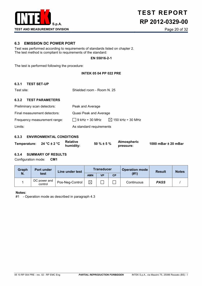
6.3 EMISSION DC POWER PORT
Test was performed according to requirements of standards listed on chapter 2. The test method is compliant to requirements of the standard:
EN 55016-2-1
The test is performed following the procedure:
INTEK 05 04 PP 022 PRE
6.3.1 TEST SET-UP
Test site: Shielded room - Room N. 25
6.3.2 TEST PARAMETERS
Preliminary scan detectors: Peak and Average
Final measurement detectors: Quasi Peak and Average
Frequency measurement range: 9 kHz ÷ 30 MHz 150 kHz ÷ 30 MHz
Limits: As standard requirements
6.3.3 ENVIRONMENTAL CONDITIONS
Temperature: 24 °C ± 2 °C Relative humidity:
50 % ± 5 % Atmospheric pressure:
1000 mBar ± 20 mBar
6.3.4 SUMMARY OF RESULTS
Configuration mode: CM1
Graph N.
Port under test
Line under test Transducer Operation mode
(#1) Result Notes
AMN VP CP
1 DC power and
control Pos-Neg-Control Continuous PASS /
Notes: #1 - Operation mode as described in paragraph 4.3

S.p.A.
TEST AND MEASUREMENT DIVISION
TEST REPORT
RP 2012-0329-00
Page 21 of 32
05 10 RP 004 PRE - rev. 02 - RP EMC Eng PARTIAL REPRODUCTION FORBIDDEN INTEK S.p.A., via Mazzini 75, 25086 Rezzato (BS) - I
Graph N. 1
S.p.A.
TEST AND MEASUREMENT DIVISION
TEST REPORT
RP 2012-0329-00
Page 22 of 32
05 10 RP 004 PRE - rev. 02 - RP EMC Eng PARTIAL REPRODUCTION FORBIDDEN INTEK S.p.A., via Mazzini 75, 25086 Rezzato (BS) - I
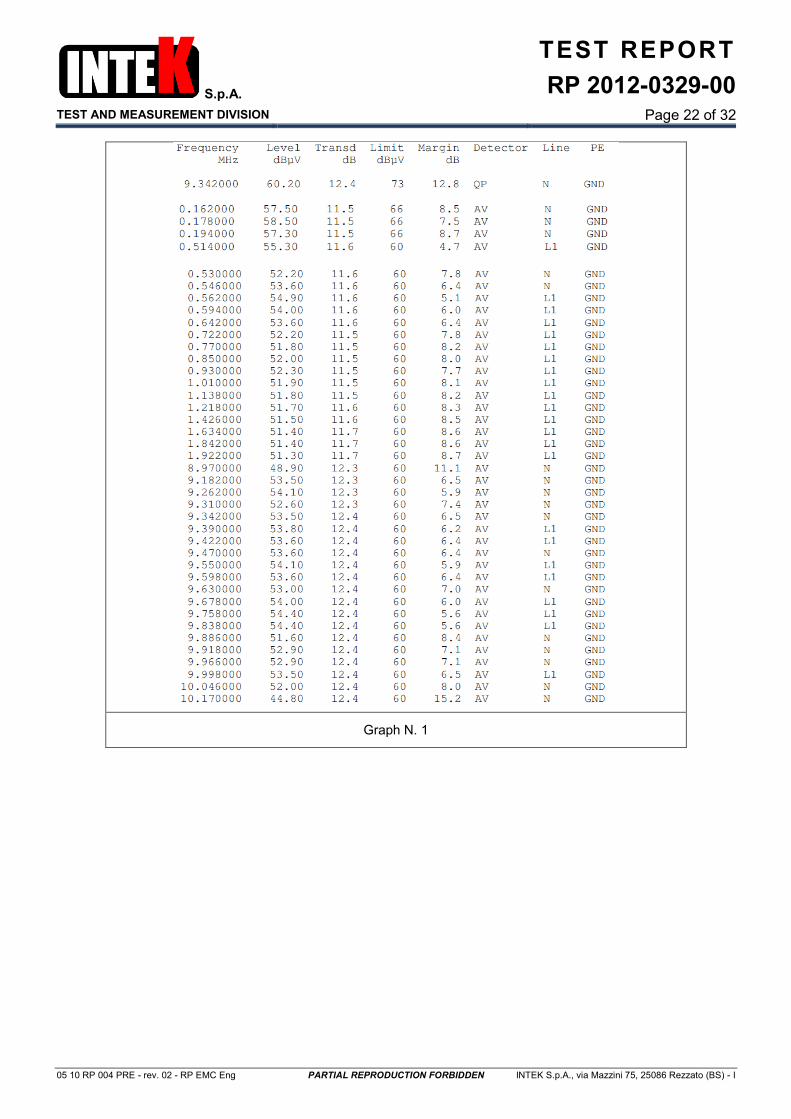
Graph N. 1
S.p.A.
TEST AND MEASUREMENT DIVISION
TEST REPORT
RP 2012-0329-00
Page 23 of 32
05 10 RP 004 PRE - rev. 02 - RP EMC Eng PARTIAL REPRODUCTION FORBIDDEN INTEK S.p.A., via Mazzini 75, 25086 Rezzato (BS) - I
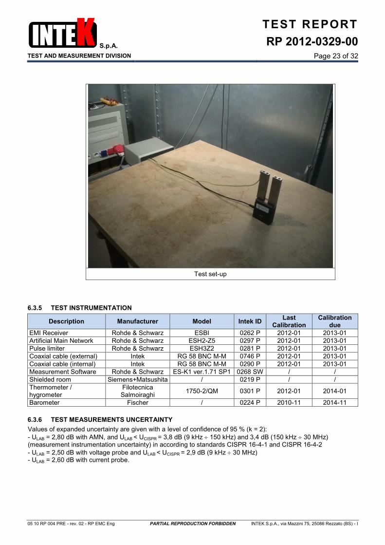
Test set-up
6.3.5 TEST INSTRUMENTATION
Description Manufacturer Model Intek ID Last
Calibration Calibration
due
EMI Receiver Rohde & Schwarz ESBI 0262 P 2012-01 2013-01
Artificial Main Network Rohde & Schwarz ESH2-Z5 0297 P 2012-01 2013-01
Pulse limiter Rohde & Schwarz ESH3Z2 0281 P 2012-01 2013-01
Coaxial cable (external) Intek RG 58 BNC M-M 0746 P 2012-01 2013-01
Coaxial cable (internal) Intek RG 58 BNC M-M 0290 P 2012-01 2013-01
Measurement Software Rohde & Schwarz ES-K1 ver.1.71 SP1 0268 SW / /
Shielded room Siemens+Matsushita / 0219 P / /
Thermometer / hygrometer
Filotecnica Salmoiraghi
1750-2/QM 0301 P 2012-01 2014-01
Barometer Fischer / 0224 P 2010-11 2014-11
6.3.6 TEST MEASUREMENTS UNCERTAINTY
Values of expanded uncertainty are given with a level of confidence of 95 % (k = 2):
- ULAB = 2,80 dB with AMN, and ULAB < UCISPR = 3,8 dB (9 kHz 150 kHz) and 3,4 dB (150 kHz 30 MHz) (measurement instrumentation uncertainty) in according to standards CISPR 16-4-1 and CISPR 16-4-2
- ULAB = 2,50 dB with voltage probe and ULAB < UCISPR = 2,9 dB (9 kHz 30 MHz) - ULAB = 2,60 dB with current probe.

S.p.A.
TEST AND MEASUREMENT DIVISION
TEST REPORT
RP 2012-0329-00
Page 24 of 32
05 10 RP 004 PRE - rev. 02 - RP EMC Eng PARTIAL REPRODUCTION FORBIDDEN INTEK S.p.A., via Mazzini 75, 25086 Rezzato (BS) - I
6.4 RADIO FREQUENCY COMMON MODE
Test was performed according to requirements of standards listed on chapter 2. The test method is compliant to requirements of the standard:
EN 61000-4-6
The test is performed following the procedure:
INTEK 05 04 PP 012 PRE
6.4.1 TEST SET-UP
Test site: Laboratory - Room N. 27
6.4.2 TEST PARAMETERS
Frequency range: 150 kHz ÷ 80 MHz 150 kHz ÷ 230 MHz
Frequency step: 1 % of previous frequency
Modulation: Sine wave - 1 kHz – 80 % - AM
Dwell time: 2 seconds at each frequency
6.4.3 ENVIRONMENTAL CONDITIONS
Temperature: 24 °C ± 2 °C Relative humidity:
50 % ± 5 % Atmospheric pressure:
1000 mBar ± 20 mBar
6.4.4 SUMMARY OF RESULTS
Configuration mode: CM1
Test voltage
(#1)
Port under test Coupling
device
Performance criteria (#2) Operation mode (#3)
Result Notes Required Obtained
10 Vrms DC power + Control CDN M3 A A Held PASS /
Notes: #1 - V (rms) unmodulated #2 - Performance criteria, given by applicable documents, as described in paragraphs 4.4 #3 - Operation mode as described in paragraph 4.3
S.p.A.
TEST AND MEASUREMENT DIVISION
TEST REPORT
RP 2012-0329-00
Page 25 of 32
05 10 RP 004 PRE - rev. 02 - RP EMC Eng PARTIAL REPRODUCTION FORBIDDEN INTEK S.p.A., via Mazzini 75, 25086 Rezzato (BS) - I
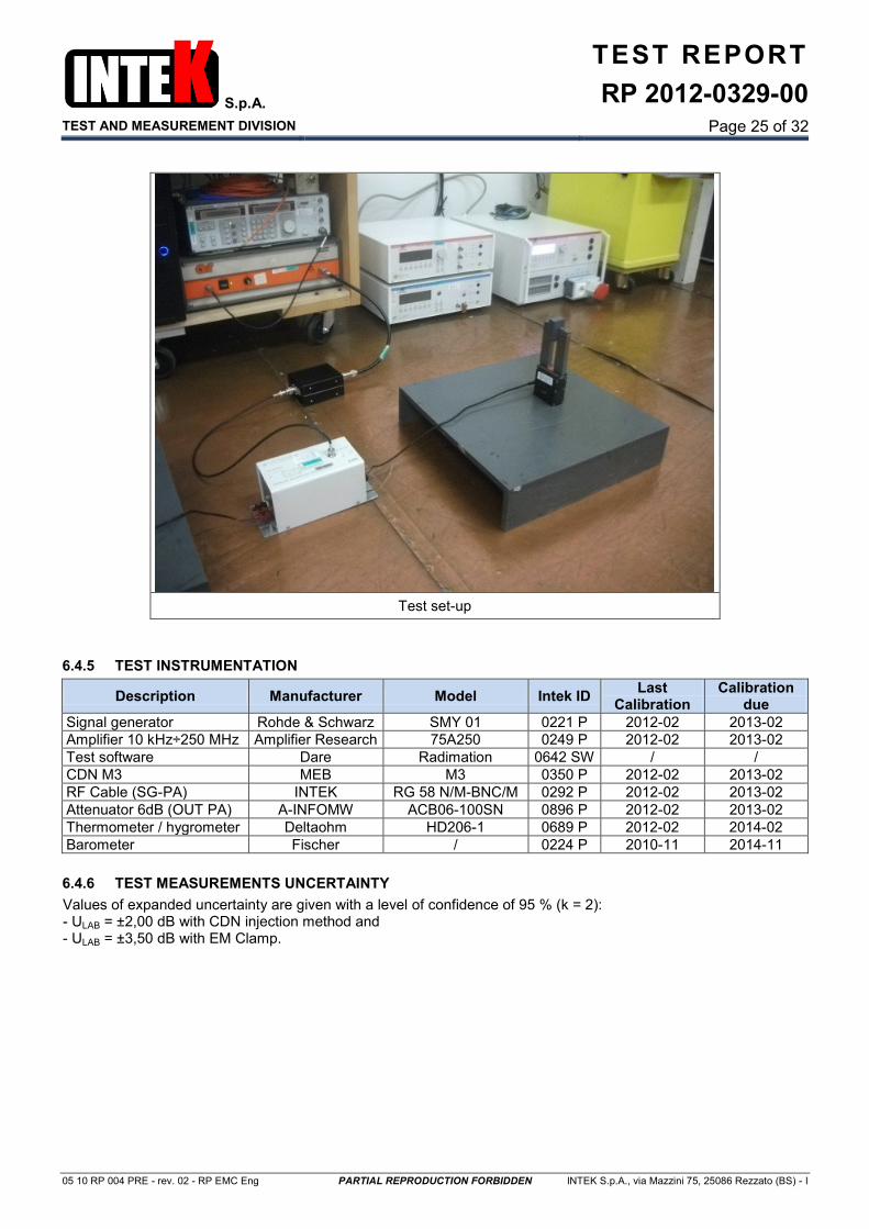
Test set-up
6.4.5 TEST INSTRUMENTATION
Description Manufacturer Model Intek ID Last
Calibration Calibration
due
Signal generator Rohde & Schwarz SMY 01 0221 P 2012-02 2013-02
Amplifier 10 kHz÷250 MHz Amplifier Research 75A250 0249 P 2012-02 2013-02
Test software Dare Radimation 0642 SW / /
CDN M3 MEB M3 0350 P 2012-02 2013-02
RF Cable (SG-PA) INTEK RG 58 N/M-BNC/M 0292 P 2012-02 2013-02
Attenuator 6dB (OUT PA) A-INFOMW ACB06-100SN 0896 P 2012-02 2013-02
Thermometer / hygrometer Deltaohm HD206-1 0689 P 2012-02 2014-02
Barometer Fischer / 0224 P 2010-11 2014-11
6.4.6 TEST MEASUREMENTS UNCERTAINTY
Values of expanded uncertainty are given with a level of confidence of 95 % (k = 2): - ULAB = ±2,00 dB with CDN injection method and - ULAB = ±3,50 dB with EM Clamp.
S.p.A.
TEST AND MEASUREMENT DIVISION
TEST REPORT
RP 2012-0329-00
Page 26 of 32
05 10 RP 004 PRE - rev. 02 - RP EMC Eng PARTIAL REPRODUCTION FORBIDDEN INTEK S.p.A., via Mazzini 75, 25086 Rezzato (BS) - I
6.5 FAST TRANSIENTS
Test was performed according to requirements of standards listed on chapter 2. The test method is compliant to requirements of the standard:
EN 61000-4-4
The test is performed following the procedure:
INTEK 05 04 PP 010 PRE
6.5.1 TEST SET-UP
Test site: Laboratory - Room N. 27
6.5.2 TEST PARAMETERS
Impulse frequency: 5 kHz
Burst duration: 15 ms
Burst repetition: 300 ms
Coupling: Asynchronous
Test duration: 1 minute for each application
Pause between test: 10 seconds
Polarity: Positive and negative
6.5.3 ENVIRONMENTAL CONDITIONS
Temperature: 24 °C ± 2 °C Relative humidity:
50 % ± 5 % Atmospheric pressure:
1000 mBar ± 20 mBar
6.5.4 SUMMARY OF RESULTS
Configuration mode: CM1
Test voltage
Port under test
Line under test
Coupling device
Performance criteria (#1) Operation mode (#2)
Result Notes Required Obtained
2 kV DC power Pos+Neg CDN B A Held PASS /
2 kV Control / CDN B A Held PASS /
Notes: #1 - Performance criteria, given by applicable documents, as described in paragraph 4.4 #2 - Operation mode as described in paragraph 4.3
S.p.A.
TEST AND MEASUREMENT DIVISION
TEST REPORT
RP 2012-0329-00
Page 27 of 32
05 10 RP 004 PRE - rev. 02 - RP EMC Eng PARTIAL REPRODUCTION FORBIDDEN INTEK S.p.A., via Mazzini 75, 25086 Rezzato (BS) - I
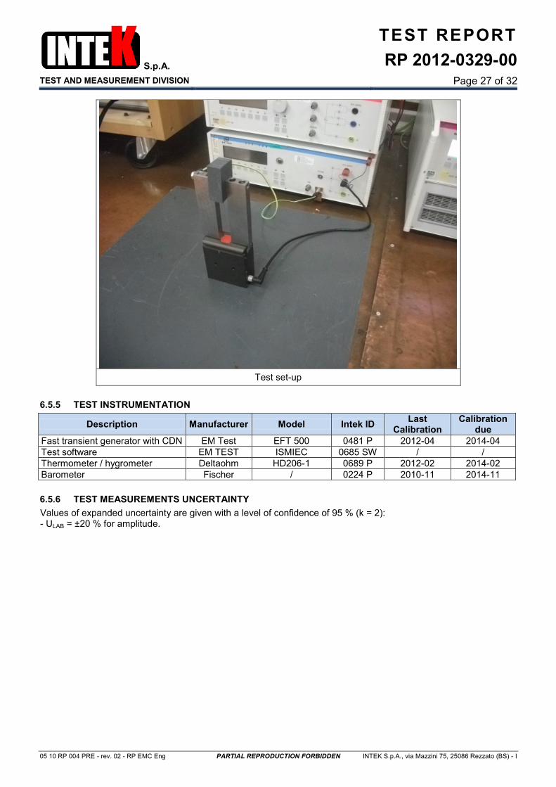
Test set-up
6.5.5 TEST INSTRUMENTATION
Description Manufacturer Model Intek ID Last
Calibration Calibration
due
Fast transient generator with CDN EM Test EFT 500 0481 P 2012-04 2014-04
Test software EM TEST ISMIEC 0685 SW / /
Thermometer / hygrometer Deltaohm HD206-1 0689 P 2012-02 2014-02
Barometer Fischer / 0224 P 2010-11 2014-11
6.5.6 TEST MEASUREMENTS UNCERTAINTY
Values of expanded uncertainty are given with a level of confidence of 95 % (k = 2): - ULAB = ±20 % for amplitude.

S.p.A.
TEST AND MEASUREMENT DIVISION
TEST REPORT
RP 2012-0329-00
Page 28 of 32
05 10 RP 004 PRE - rev. 02 - RP EMC Eng PARTIAL REPRODUCTION FORBIDDEN INTEK S.p.A., via Mazzini 75, 25086 Rezzato (BS) - I
6.6 ELECTROSTATIC DISCHARGES
Test was performed according to requirements of standards listed on chapter 2. The test method is compliant to requirements of the standard:
EN 61000-4-2
The test is performed following the procedure:
INTEK 05 04 PP 001 PRE
6.6.1 TEST SET-UP
Test site: Laboratory - Room N. 27
6.6.2 TEST PARAMETERS
Repetition rate: 1 discharge every 1 second for contact method
Number of discharges for contact discharge type: 10 discharges
Number of discharges for air discharge type: 10 discharges
Polarity: Positive and negative
6.6.3 ENVIRONMENTAL CONDITIONS
Temperature: 24 °C ± 2 °C Relative humidity:
50 % ± 5 % Atmospheric pressure:
1000 mBar ± 20 mBar
6.6.4 SUMMARY OF RESULTS
Port under test: Enclosure
Configuration mode: CM1
Test voltage
Coupling method
Discharge point
Performance criteria (#1)
Operation mode (#2)
Result Notes
Required Obtained
2 kV 4 kV 8 kV
Air Non conductive
parts B / / N/A #3
2 kV 4 kV
Direct discharge
Conductive parts B A Held PASS /
2 kV 4 kV
Indirect discharge
VCP B A Held PASS /
2 kV 4 kV
Indirect discharge
HCP B A Held PASS /
Notes: #1 - Performance criteria, given by applicable documents, as described in paragraph 4.4 #2 - Operation mode as described in paragraph 4.3 #3 - The test sample has no accessible insulating surface.

S.p.A.
TEST AND MEASUREMENT DIVISION
TEST REPORT
RP 2012-0329-00
Page 29 of 32
05 10 RP 004 PRE - rev. 02 - RP EMC Eng PARTIAL REPRODUCTION FORBIDDEN INTEK S.p.A., via Mazzini 75, 25086 Rezzato (BS) - I
Test set-up
Legend Air discharge Contact discharge
Point of application of the discharges
6.6.5 TEST INSTRUMENTATION
Description Manufacturer Model Intek ID Last
Calibration Calibration
due
ESD Generator EMC-Partner ESD-3000 0764 P 2011-02 2013-02
RC filter 150 pF – 330 Ω EMC-Partner ESD3000DN1 0765 P 2011-02 2013-02
High-voltage relay module EMC-Partner ESD3000RM32 0769 P 2011-02 2013-02
Grounding cable EMC-Partner / 0807 A 2011-02 2013-02
HCP + 2x470 k bleeder INTEK / 0808 A / /
VCP + 2x470 k bleeder INTEK / 0808 A / /
Thermometer / hygrometer Deltaohm HD206-1 0689 P 2012-02 2014-02
Barometer Fischer / 0224 P 2010-11 2014-11
6.6.6 TEST MEASUREMENTS UNCERTAINTY
Values of expanded uncertainty are given with a level of confidence of 95 % (k = 2): - ULAB = ±5,00 % for voltage.

S.p.A.
TEST AND MEASUREMENT DIVISION
TEST REPORT
RP 2012-0329-00
Page 30 of 32
05 10 RP 004 PRE - rev. 02 - RP EMC Eng PARTIAL REPRODUCTION FORBIDDEN INTEK S.p.A., via Mazzini 75, 25086 Rezzato (BS) - I
6.7 SURGES
Test was performed according to requirements of standards listed on chapter 2. The test method is compliant to requirements of the standard:
EN 61000-4-5
The test is performed following the procedure:
INTEK 05 04 PP 011 PRE
6.7.1 TEST SET-UP
Test site: Laboratory - Room N. 27
6.7.2 TEST PARAMETERS
Impulse waveform: 1,2 / 50 μs OC - 8 / 20 μs SC
Number of impulses for type: 5
Coupling angle:
0° / 90° / 180° / 270°
Positive pulse at 90° and negative pulse at 180°
Asynchronous
Repetition rate: 1 minute
Polarity: Positive and negative
6.7.3 ENVIRONMENTAL CONDITIONS
Temperature: 24 °C ± 2 °C Relative humidity:
50 % ± 5 % Atmospheric pressure:
1000 mBar ± 20 mBar
6.7.4 SUMMARY OF RESULTS
Port under test: DC power
Configuration mode: CM1
Test voltage
Coupling impedance
Injection points
Performance criteria (#1)
Operation mode (#2)
Result Notes
Required Obtained
0,5 kV 12 Ω + 9 μF Positive Earth B A Held PASS #3
0,5 kV 12 Ω + 9 μF Negative Earth B A Held PASS #3
0,5 kV 2 Ω + 18 μF Positive Negative B A Held PASS #3
Notes: #1 - Performance criteria, given by applicable documents, as described in paragraph 4.4 #2 - Operation mode as described in paragraph 4.3 #3 - After modifications described in paragraph 4.1.2.
S.p.A.
TEST AND MEASUREMENT DIVISION
TEST REPORT
RP 2012-0329-00
Page 31 of 32
05 10 RP 004 PRE - rev. 02 - RP EMC Eng PARTIAL REPRODUCTION FORBIDDEN INTEK S.p.A., via Mazzini 75, 25086 Rezzato (BS) - I
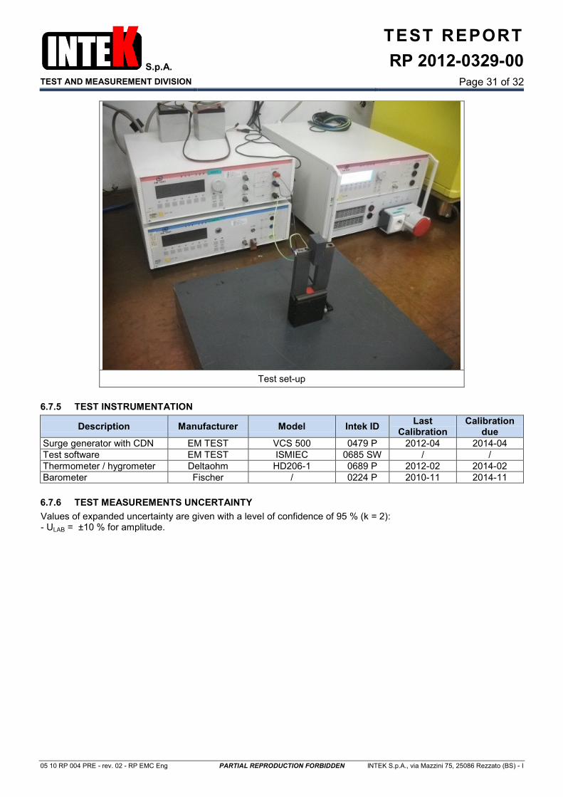
Test set-up
6.7.5 TEST INSTRUMENTATION
Description Manufacturer Model Intek ID Last
Calibration Calibration
due
Surge generator with CDN EM TEST VCS 500 0479 P 2012-04 2014-04
Test software EM TEST ISMIEC 0685 SW / /
Thermometer / hygrometer Deltaohm HD206-1 0689 P 2012-02 2014-02
Barometer Fischer / 0224 P 2010-11 2014-11
6.7.6 TEST MEASUREMENTS UNCERTAINTY
Values of expanded uncertainty are given with a level of confidence of 95 % (k = 2): - ULAB = ±10 % for amplitude.

S.p.A.
TEST AND MEASUREMENT DIVISION
TEST REPORT
RP 2012-0329-00
Page 32 of 32
05 10 RP 004 PRE - rev. 02 - RP EMC Eng PARTIAL REPRODUCTION FORBIDDEN INTEK S.p.A., via Mazzini 75, 25086 Rezzato (BS) - I
7. TEST INSTRUMENTATION
The list of instruments is given in the relative paragraph of each test.
8. EUT DOCUMENTATION
Description Code Date - revision
User manual Not available /
Component list MRE32180-17 BOM 2012-10-26 - rev. 1.1
Wiring diagram MRE32180-17 2012-10-26 - rev. 1.1
A copy of the listed above documents is archived in Intek S.p.A.
9. ANNEXES LIST
None.
End of test report.