Embed Size (px)
Citation preview
Etablissement de Nantes74, route de la JonelièreBP 8232644326 Nantes Cedex 3
Téléphone : +33 2 40 37 35 86Télécopie : +33 2 51 86 00 73
For
To
Réf. of request
- This report concerns only the tested objects.- Reproduction of this report is permitted only in its integral form. The report includes 18 pages
Specimens supplied by the customer :
Report n° Date :
Subject :
Final report :
TEST REPORT
HL/MT
The french version is legally acceptable.
"Conditions générales de vente et d’exécution des prestations" : see over leaf.
M ROTH RODNEY
TEADIT558 Garden Oaks BLVDTX770 HOUSTONUSA
Your oder by e-mail n°125256
12/11/2002736219/6J1/c
HOBT - TEADIT 1590 1/8"
TEADIT 1590 1/8"
December 11th, 2002 N° 736219/6J1/c Page 2
1 - AIM OF TEST
Increasing use of PTFE gasket products for difficult service and as substitute for asbestos and no-nasbestos fiber reinforced materials has fostered interest in developing standard test protocols thatmeasure and qualify the performance of PTFE based gaskets on the basis of a direct measure of theirmargin of safety against blow-out. This has led to the development of a HOt Blow-out Test (HOBT)for gauging PTFE gasket tightness performance under extreme relaxation conditions.
The main goal of this test is to determine the gasket resistance to hot relaxation and the gross lea-kage susceptibility to blow-out conditions.
2 - HOBT TEST PROCEDURE
2.1 - HOBT without thermal cycles procedure
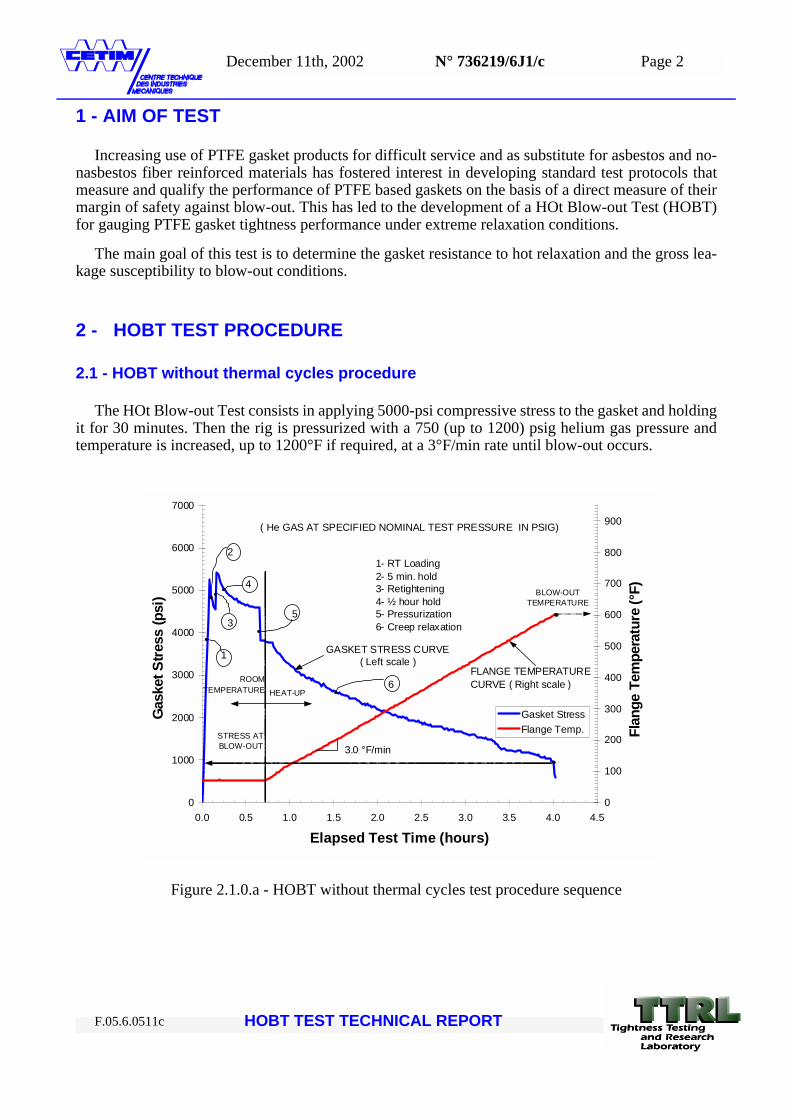
The HOt Blow-out Test consists in applying 5000-psi compressive stress to the gasket and holdingit for 30 minutes. Then the rig is pressurized with a 750 (up to 1200) psig helium gas pressure andtemperature is increased, up to 1200°F if required, at a 3°F/min rate until blow-out occurs.
Figure 2.1.0.a - HOBT without thermal cycles test procedure sequence
0
1000
2000
3000
4000
5000
6000
7000
0.0 0.5 1.0 1.5 2.0 2.5 3.0 3.5 4.0 4.5
Elapsed Test Time (hours)
Gas
ket S
tress
(psi
)
0
100
200
300
400
500
600
700
800
900
Flan
ge T
empe
ratu
re (°
F)
Gasket StressFlange Temp.
FLANGE TEMPERATURECURVE ( Right scale )
GASKET STRESS CURVE( Left scale )
BLOW-OUTTEMPERATURE
STRESS ATBLOW-OUT
ROOMTEMPERATURE HEAT-UP
3.0 °F/min
( He GAS AT SPECIFIED NOMINAL TEST PRESSURE IN PSIG)
3
6
4
2
1
5
1- RT Loading2- 5 min. hold3- Retightening4- ½ hour hold5- Pressurization6- Creep relaxation
HOBT TEST TECHNICAL REPORT F.05.6.0511c
December 11th, 2002 N° 736219/6J1/c Page 3
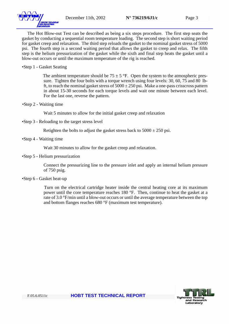
The Hot Blow-out Test can be described as being a six steps procedure. The first step seats thegasket by conducting a sequential room temperature loading. The second step is short waiting periodfor gasket creep and relaxation. The third step reloads the gasket to the nominal gasket stress of 5000psi. The fourth step is a second waiting period that allows the gasket to creep and relax. The fifthstep is the helium pressurization of the gasket while the sixth and final step heats the gasket until ablow-out occurs or until the maximum temperature of the rig is reached.
•Step 1 - Gasket Seating
The ambient temperature should be 75 ± 5 °F. Open the system to the atmospheric pres-sure. Tighten the four bolts with a torque wrench using four levels: 30, 60, 75 and 80 lb-ft, to reach the nominal gasket stress of 5000 ± 250 psi. Make a one-pass crisscross patternin about 15-30 seconds for each torque levels and wait one minute between each level.For the last one, reverse the pattern.
•Step 2 - Waiting time
Wait 5 minutes to allow for the initial gasket creep and relaxation
•Step 3 - Reloading to the target stress level
Retighten the bolts to adjust the gasket stress back to 5000 ± 250 psi.
•Step 4 - Waiting time
Wait 30 minutes to allow for the gasket creep and relaxation.
•Step 5 - Helium pressurization
Connect the pressurizing line to the pressure inlet and apply an internal helium pressureof 750 psig.
•Step 6 - Gasket heat-up
Turn on the electrical cartridge heater inside the central heating core at its maximumpower until the core temperature reaches 180 °F. Then, continue to heat the gasket at arate of 3.0 °F/min until a blow-out occurs or until the average temperature between the topand bottom flanges reaches 680 °F (maximum test temperature).
HOBT TEST TECHNICAL REPORT F.05.6.0511c
December 11th, 2002 N° 736219/6J1/c Page 4
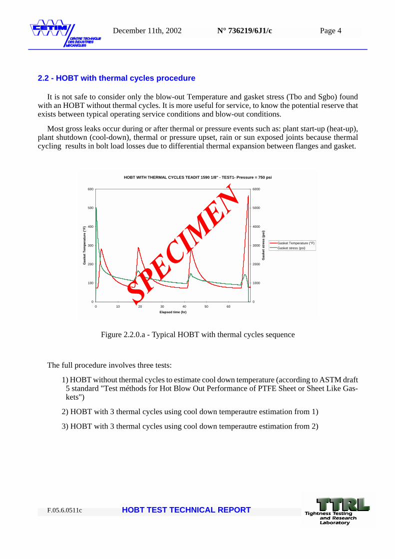
2.2 - HOBT with thermal cycles procedure
It is not safe to consider only the blow-out Temperature and gasket stress (Tbo and Sgbo) foundwith an HOBT without thermal cycles. It is more useful for service, to know the potential reserve thatexists between typical operating service conditions and blow-out conditions.
Most gross leaks occur during or after thermal or pressure events such as: plant start-up (heat-up),plant shutdown (cool-down), thermal or pressure upset, rain or sun exposed joints because thermalcycling results in bolt load losses due to differential thermal expansion between flanges and gasket.
Figure 2.2.0.a - Typical HOBT with thermal cycles sequence
The full procedure involves three tests:
1) HOBT without thermal cycles to estimate cool down temperature (according to ASTM draft5 standard "Test méthods for Hot Blow Out Performance of PTFE Sheet or Sheet Like Gas-kets")
2) HOBT with 3 thermal cycles using cool down temperautre estimation from 1)
3) HOBT with 3 thermal cycles using cool down temperautre estimation from 2)
HOBT WITH THERMAL CYCLES TEADIT 1590 1/8" - TEST1- Pressure = 750 psi
0
100
200
300
400
500
600
0 10 20 30 40 50 60Elapsed time (hr)
Gas
ket T
empe
ratu
re (°
F)
0
1000
2000
3000
4000
5000
6000
Gas
ket s
tres
s (p
si)
Gasket Temperature (°F)Gasket stress (psi)
HOBT TEST TECHNICAL REPORT F.05.6.0511c
December 11th, 2002 N° 736219/6J1/c Page 5
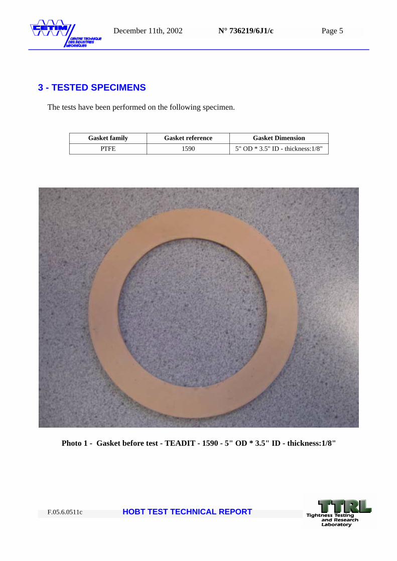
3 - TESTED SPECIMENS
The tests have been performed on the following specimen.
Photo 1 - Gasket before test - TEADIT - 1590 - 5" OD * 3.5" ID - thickness:1/8"
Gasket family Gasket reference Gasket DimensionPTFE 1590 5" OD * 3.5" ID - thickness:1/8"
HOBT TEST TECHNICAL REPORT F.05.6.0511c
December 11th, 2002 N° 736219/6J1/c Page 6
4 - TESTING EQUIPMENT AND MEASUREMENT INSTRUMENTS
The Hot Blow-out Test Rig is designed to reproduce hot blow-out conditions in a real gasketedflanged joint subjected to a maximum compressive load of 50000 lb, at a working temperature of upto 750 °F and with helium gas pressure up to 1000 psig. Tested gaskets are NPS 3", 3.5" ID x 5" ODfor sheet gaskets, with a surface area of about 10 in2.
The rig is composed of a pair of standard NPS 3" Class 150 flanges with raised faces.Both flangesare welded to schedule 80 pipes and are equipped with four 5/8" - 18 UNF high-strength steel bolts.The flange surface finish is in accordance with the ASME/ANSI B16.5 standard. The joint axial rigi-dity is evaluated to 4.4x10⁶ lb/in.
Flanges are mounted on a steel cylindrical core welded to a steel base plate. Gasket loading is per-formed with a torque wrench, and the usual criss-cross sequence is used to torque the four bolts. Thesecalibrated bolts are equipped with special extensometers to measure the bolt stretch that is converterto bolt load. Each extensometer consists of a pair of long ceramic rods that are spring loaded. The ex-tensometers are compensated for thermal effects. To measure bolt strech, a displacement transduceris placed at the end of each extensometer. These transducers are placed at the bottom of the rig, wellbelow the heated zone, and measure the relative displacement between the pair of ceramic rods.
The helium gas is supplied by a high-pressure gas cylinder.The pressure is adjusted with a precisemanual pressure regulator and it is measured with an electronic pressure transducer.
The central heating core is embedded with a 2000 W electrical cartridge heater. An electronic tem-perature controller is used to achieve a constant temperature increase of 3.0 °F/min. Temperature ismeasured at three locations: in the solid core and inside the top and the bottom flanges at mid gasketdiameter, close to the raised face surface.
The top and bottom parts of the fixture are insulated to minimize thermal gradients. The top insu-lation casing is removable to allow for gasket change and bolt torquing.
A manual relief valve permits gas purging during heating to prevent internal pressure increase.Inorder to minimize the gas flow when a blow-out occurs, the gas volume inside the fixture is minimizedby the use of the solid central core and the gas flow from the pressure regulator is restricted by a mi-crometric valve. Gasket deflection and leakage are not measured during the HOBT test.
HOBT rig technical data summary
Rig flanges: NPS 3" Class 150 Slip-on
Rig bolts: 4 bolts 5/8"-18UNF
Pressurizing gas:Helium
Nominal gas pressures:4750 psig
Nominal initial gasket stress: 5000 ± 250 psi
Initial gasket temperature:75 ± 5 °F
Heating rate: 3.0 °F/min.
HOBT TEST TECHNICAL REPORT F.05.6.0511c
December 11th, 2002 N° 736219/6J1/c Page 7
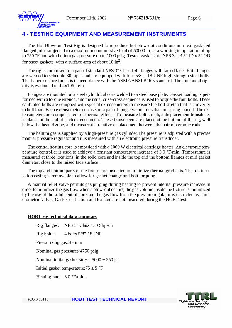
Photo 2 - HOBT test rig
HOBT rig – general view
HOBT rig – detail
HOBT rig – upper flange 3 ‘’ 150 lbs-
HOBT rig – PTFE Gasket Blow Out example
HOBT TEST TECHNICAL REPORT F.05.6.0511c
December 11th, 2002 N° 736219/6J1/c Page 8
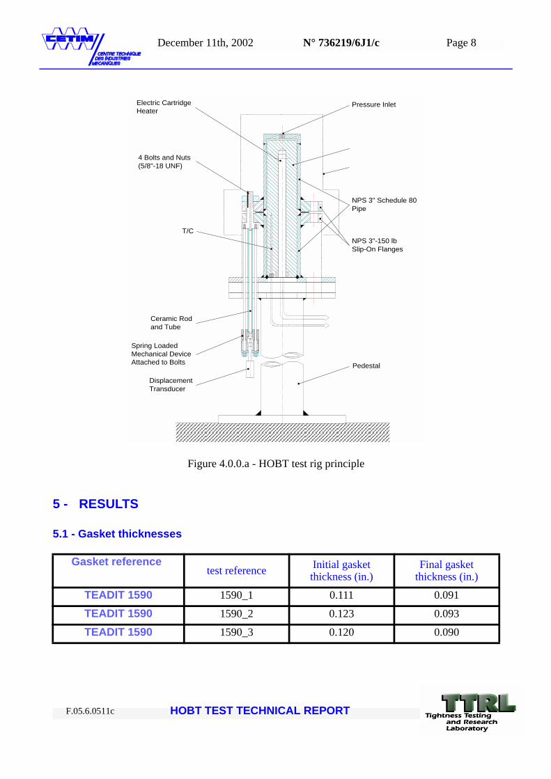
Figure 4.0.0.a - HOBT test rig principle
5 - RESULTS
5.1 - Gasket thicknesses
Gasket referencetest reference Initial gasket
thickness (in.)Final gasket
thickness (in.)
TEADIT 1590 1590_1 0.111 0.091
TEADIT 1590 1590_2 0.123 0.093
TEADIT 1590 1590_3 0.120 0.090
NPS 3"-150 lbSlip-On Flanges
NPS 3" Schedule 80Pipe
Pressure Inlet
4 Bolts and Nuts(5/8"-18 UNF)
T/C
Ceramic Rodand Tube
Spring LoadedMechanical DeviceAttached to Bolts
DisplacementTransducer
Pedestal
Electric CartridgeHeater
HOBT TEST TECHNICAL REPORT F.05.6.0511c
December 11th, 2002 N° 736219/6J1/c Page 9
5.2 - HOBT results
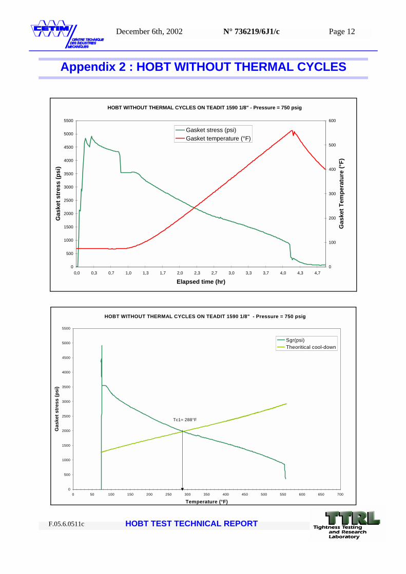
The first HOBT test without thermal cycles leads to a first cool down temperature of Tc1=288°F.This cool down temperature is computed following ASTM draft for HOBT)
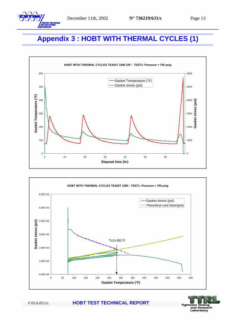
Conduction of the second test with this new temperature (Tc1) as cool down temperature leads toa new predicted cool down temperatrure: Tc2=281° F.
Conduction of a third test with this new temperature (Tc2) as cool down temperature leads to a newpredicted cool down temperatrure: Tc3=299° F.
5.3 - Conclusion
According to the HOBT test results, the safe cool-down reserve temperature for TEADIT 1590 1/8" is 281°F lowest value from safe cool-down reserve temperature from 3 tests.
6 - APPENDICES LIST
- APPENDIX 1: Gasket after test
- APPENDIX 2: HOBT without thermal cycles
- APPENDIX 3: HOBT with thermal cycles (1)
- APPENDIX 4: HOBT with thermal cycles (2)
Gasket reference Thermal cycles
Test reference
BLOW OUT VALUES Cool down Temp. (°F)
Blow out Temp. (°F)
Blow out Stress (psi)
Blow out Pressure
(psig)
TEADIT 1590 NO 1590_1 554 847 760 288
TEADIT 1590 YES 1590_2 559 757 772 281
TEADIT 1590 YES 1590_3 568 670 745 299
HOBT TEST TECHNICAL REPORT F.05.6.0511c
December 11th, 2002 N° 736219/6J1/c Page 10
Appendix I : GASKET PICTURES AFTER TEST
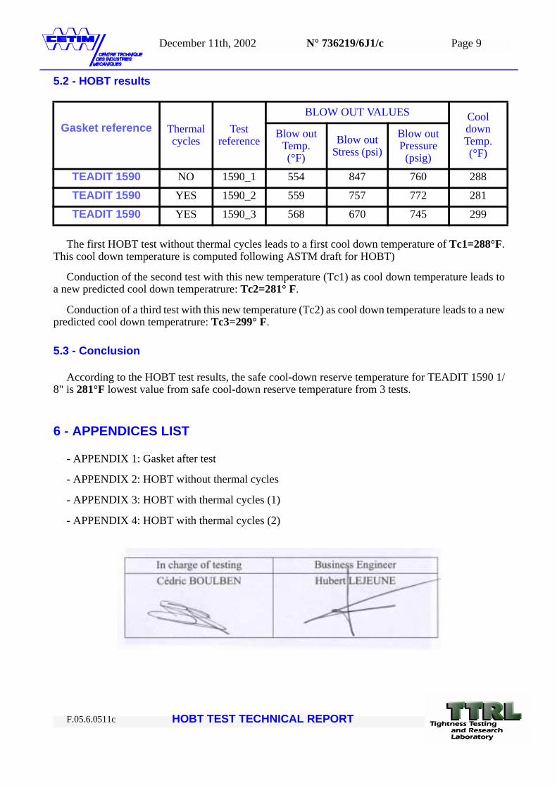
Photo 1 - Gasket after test 1 (without thermal cycle)
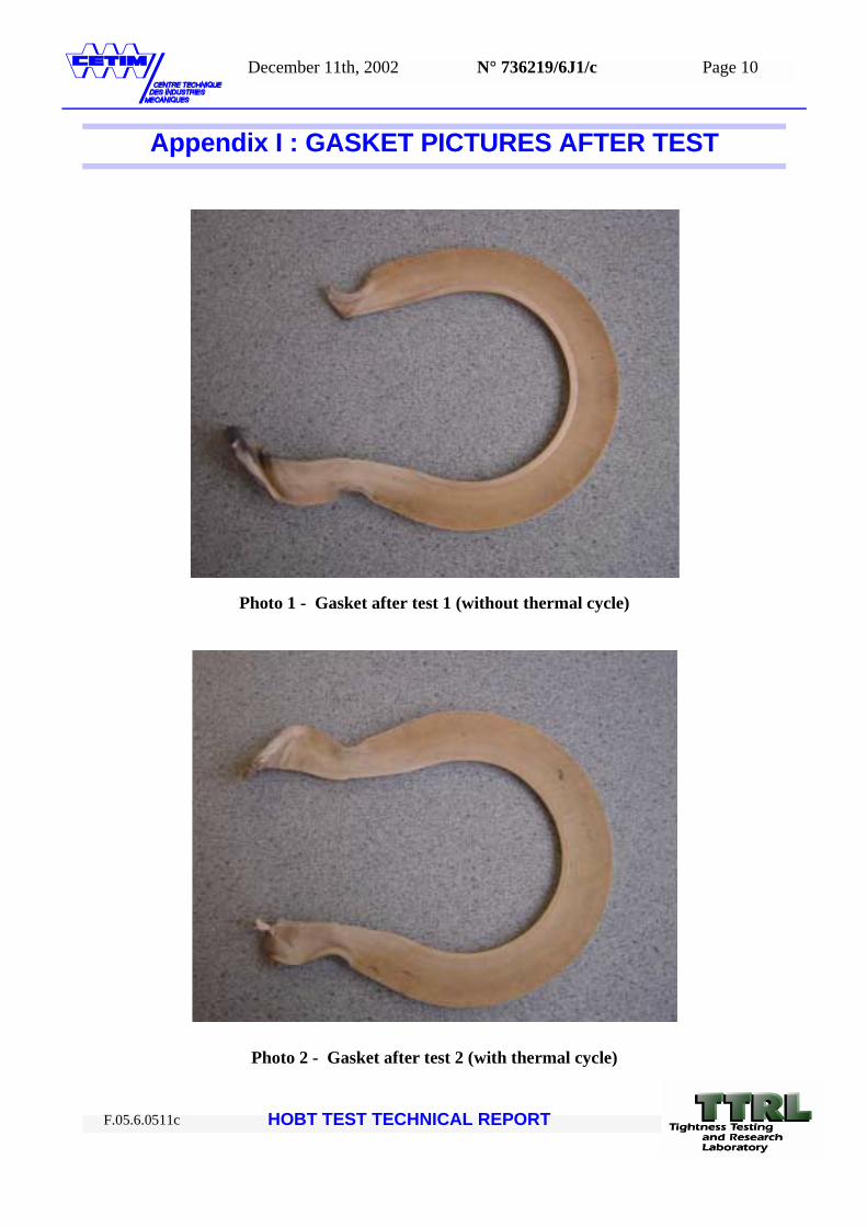
Photo 2 - Gasket after test 2 (with thermal cycle)
HOBT TEST TECHNICAL REPORT F.05.6.0511c
December 11th, 2002 N° 736219/6J1/c Page 11
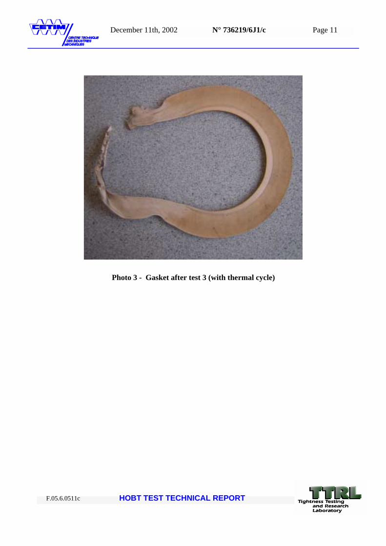
Photo 3 - Gasket after test 3 (with thermal cycle)
HOBT TEST TECHNICAL REPORT F.05.6.0511c
December 6th, 2002 N° 736219/6J1/c Page 12
HOBT TEST TECHNICAL REPORT F.05.6.0511c
Appendix 2 : HOBT WITHOUT THERMAL CYCLES
HOBT WITHOUT THERMAL CYCLES ON TEADIT 1590 1/8" - Pressure = 750 psig
0
500
1000
1500
2000
2500
3000
3500
4000
4500
5000
5500
0,0 0,3 0,7 1,0 1,3 1,7 2,0 2,3 2,7 3,0 3,3 3,7 4,0 4,3 4,7
Elapsed time (hr)
Gas
ket s
tres
s (p
si)
0
100
200
300
400
500
600
Gas
ket T
empe
ratu
re (°
F)
Gasket stress (psi)Gasket temperature (°F)
HOBT WITHOUT THERMAL CYCLES ON TEADIT 1590 1/8" - Pressure = 750 psig
0
500
1000
1500
2000
2500
3000
3500
4000
4500
5000
5500
0 50 100 150 200 250 300 350 400 450 500 550 600 650 700
Temperature (°F)
Gas
ket s
tres
s (p
si)
Sgr(psi)Theoritical cool-down
Tc1= 288°F
December 11th, 2002 N° 736219/6J1/c Page 13
HOBT TEST TECHNICAL REPORT F.05.6.0511c
Appendix 3 : HOBT WITH THERMAL CYCLES (1)
HOBT WITH THERMAL CYCLES TEADIT 1590 1/8" - TEST1- Pressure = 750 psig
0
100
200
300
400
500
600
0 10 20 30 40 50 60
Elapsed time (hr)
Gas
ket T
empe
ratu
re (°
F)
0
1000
2000
3000
4000
5000
6000
Gas
ket s
tres
s (p
si)
Gasket Temperature (°F)Gasket stress (psi)
HOBT WITH THERMAL CYCLES TEADIT 1590 - TEST1- Pressure = 750 psig
0,00E+00
1,00E+03
2,00E+03
3,00E+03
4,00E+03
5,00E+03
6,00E+03
0 50 100 150 200 250 300 350 400 450 500 550 600
Gasket Temperature (°F)
Gas
ket s
tres
s (p
si)
Gasket stress (psi)Theoritical cool down(psi)
Tc2=281°F

December 11th, 2002 N° 736219/6J1/c Page 14
HOBT TEST TECHNICAL REPORT F.05.6.0511c
Appendix 4 : HOBT WITH THERMAL CYCLES (2)
HOBT WITH THERMAL CYCLES TEADIT 1590 1/8" - TEST2- Pressure=750 psig
0
100
200
300
400
500
600
700
0 10 20 30 40 50 60 70
Elapsed time (hr)
Gas
ket T
empe
ratu
re (°
F)
0
500
1000
1500
2000
2500
3000
3500
4000
4500
5000
5500
Gas
ket s
tres
s (p
si)
Gasket Temperature (°F)Gasket stress (psi)
HOBT WITH THERMAL CYCLES TEADIT 1590 - TEST2- Pressure = 750 psig
0
500
1000
1500
2000
2500
3000
3500
4000
4500
5000
5500
0 100 200 300 400 500 600 700
Gasket Temperature (°F)
Gas
ket s
tres
s (p
si)
Gasket stress (psi)Theoritical cool down(psi)
Tc3=299°F