Embed Size (px)
Citation preview

Project: Fanidhar Mega Food ParkSubject: Summary Sheet
Summary of WorksAmount (INR)
Part - A Civil Works -
Part - B Pumps and Panel Works -
Part - C Fire Protection Works -
Total (A) - Taxes (B) - Total Amount (A+B) -

KB: BOQ FOR CIVIL, STRUCTURAL AND INFRASTRUCTURE WORKS FOR MFP SERVICE AND UTILITY INFRASTRUCTURE AT FANIDHAR
DESCRIPTION UNIT QUANTITY
Road
100 EXCAVATION101
101A FOR DEPTH UPTO 1.5M M3 0101B FOR DEPTH (1.5-3.0M) M3 0101C FOR DEPTH (3.0-4.5M) M3 0104 CARTING MATERIAL FROM SITE M3 2738
106 0
106C M3 18203
0200 CONCRETE 0201 PLAIN CEMENT CONCRETE 0
201B AS PER 201 1:4:8 P.C.C. M3 0201D AS PER 201 1:2:4 P.C.C. M3 0
210 0
210A AT AND BELOW PLINTH LEVEL M3 0
211 0
211A AT AND BELOW PLINTH LEVEL M3 0211B PLINTH TO 4.5 M M3 0215 PVC WATER STOPPER 0
215A 150MM WIDE SINGLE BULB WITH 8-11MM THICK M 0215B 230MM WIDE SINGLE BULB WITH 10MM THICK M 0
224 0
224C FOR M30 GRADE CONCRETE M3 00
300 FORMWORK 0301 FORMWORK FOR CONCRETE 0
301A AT AND BELOW PLINTH M2 0301B PLINTH TO 4.5M M2 0
305 M2 0
308 FILLER BOARD FOR EXPANSION JOINT 0308B 25MM THICK BOARD M2 0309 SEALENT FOR EXPANSION JOINT 0
ITEM NO.
EXCAVATION FOR FOUNDATION PITS TRENCHES ETC.
SUPPLY-FILL-COMPACT APPROVED EARTH BROUGHT FROM OUTSIDEAS PER 106 BUT USING MECH. VIBRO ROLLER (EARTHWORK)
M25 CONC. IN FOUNDATIONS, PEDESTALS, COLUMNS, BEAMS, COPINGS, WALLS, SLABS, SHELVES, STAIRS ETC.
M30 CONC. IN FOUNDATIONS, PEDESTALS, COLUMNS, BEAMS, COPINGS, WALLS, SLABS, SHELVES, STAIRS ETC.
PROVIDING & LAYING OF READY MIXED CONCRETE
EXTRA OVER 301 FOR PROVIDING STAGING OF HEIGHT MORE THAN 4.5M FROM FINISH FLOOR LEVEL (ONLY ADDITIONAL COST FOR STAGING SHOULD BE CONSIDERED)

309C GROOVE SIZE 25MM X 12MM DEEP M 00
400 REINFORCEMENT 0
403 MT 0
0500 BRICK MASONRY 0
513 0
513A PLINTH TO 4.5M M3 0513B 4.5M TO 9.0M FROM PLINTH M3 0
0600 WATER PROOFING 0
603 M2 0
614 M2 0
0700 FLOORING 0702 50MM THICK IPS WITH IRONITE M2 0
710 0
710A AS PER 710 FOR WHITE GLAZED TILES M2 0718 IMMEDIATE FINISH ON CONCRETE SURFACE. M2 0729 BROKEN CHINA MOSAIC FLOORING M2 0769 WINDOW SILL 0
769B GRANITE STONE M2 0
773 M2 0
774 M2 0
0800 DOORS & WINDOWS 0826 ALUMINIUM LOUVERS 0
826A SAME AS 826 BUT FOR FIXED TYPE LOUVERS M2 0876 ALUMINIUM WINDOW - FIXED TYPE 0
876A M2 0
877 PRE COLOUR COATED GI ROLLING SHUTTER M2 00
900 PLASTERING 0
902 DOUBLE COAT SAND FACED CEMENT PLASTER M2 0
903 FIXING HEXAGONAL CHICKEN MESH M2 0904 20MM WATER PROOF PLASTER M2 0908 20MM THK DOUBLE COAT MALA PLASTER M2 0916 SINGLE COAT MALA PLASTEER M2 0952 STONE PITCHING M2 0
01000 PAINTING 01009 THREE COATS OF PLASTIC EMULSION PAINT M2 0
HIGH STRENGTH DEFORMED BARS MINIMUM Fe-500 N/MM2
AUTOCLAVED AERATED CONCRETE BLOCK MASONRY
WATER PROOFING FOR HORI-VERT AND RETURNS FOR TERRACEINTEGRAL PENETRATING CRYSTALLINE WATERPROOFING
GLAZED TILES/CERAMIC TILES / MARBLE TILES IN FLOORING & DADO
60 MM THICK SHOT BLASTED FLAGSTONE OF VYARA OR EQUIVALENT60 MM THICK SHOT BLASTED COBBLE OF VYARA OR EQUIVALENT
SAME AS 876 BUT UPTO 4KG/M2 OF OPENING AREA

1011 M2 0
1015 M2 0
1021 PLASTER SURFACE FINISHED WITH BIRLA PUTTY M2 0
1022 THERMOPLASTIC PAINT (150 MM WIDE STRIPS) M 121380
1100 ROOFING AND CLADDING 01123 uPVC RAIN WATER PIPES (Class-5 Rating) 0
1123A AS PER 1123 BUT 110 DIA PIPES M 00
1200 STRUCTURAL STEEL WORK 0
1201 MT 0
1202 STEEL INSERTS KG 01204 CHEQUERED PLATE MT 0
01300 WATER SUPPLY AND SANITARY 01323 INSPECTION CHAMBER 0
1323A NO 0
1323D NO 0
1323E NO 0
1324 MANHOLE 01324A FOR DEPTH UP TO 1500MM (750MM x 750MM) NO 101324B FOR DEPTH UP TO 1000MM (1000MM x 1000MM) NO 61324C FOR DEPTH OF 2000MM (1200MM x 1200MM) NO 31324D FOR DEPTH OF 1500MM (1000MM x 1000MM) NO 661324E FOR DEPTH OF 2000MM (1000MM x 1000MM) NO 25
1339 NO 0
1340 0
1340A FOR 900 X 600 MM COVER NO 01340B FOR 600 X 600 MM COVER NO 01340C FOR 800 X 800 MM COVER NO 01341 VALVE CHAMBER 0
1341A NO 0
1346 CATCHPIT CHAMBER 0
THREE COATS OF ACRYLIC BASED PAINT "APEX" OR EQUIVALENTTWO COATS OF SILICON PAINT OVER EXPOSED RCC SURFACE
STRUCTURAL STEEL WORK INCLUDING ONE COAT ZINC CHROMATE PRIMER AND TWO COATS OF ENAMEL PAINT
INTERNAL SIZE 900 X 800 - UPTO 1000 MM DEEP; WITH 600 X 600 MM, HEAVY DUTY (C-250), WT : 150 KG
INTERNAL SIZE 1200 X 900 MM DIA - UPTO 3000 MM DEPTH; WITH 900 X 450 MM, HEAVY DUTY (C-250), WT : 150 KG
INTERNAL SIZE 1200 X 1200 MM DIA - UPTO 1500 MM DEPTH; WITH 900 X 600 MM, HEAVY DUTY (C-250), WT : 150 KG
D.I. MAN HOLE COVER WITH FRAME (HEAVY DUTY) - 600 MM DIA
EXTRA OVER INSTEAD OF DI MANHOLE COVER IN THE RESPECTIVE ITEMS FOR DUCTILE IRON MANHOLE SQUARE COVER OF “CRESCENT OR APPROVED EQUIVALENT MAKE” FOR D400 LOADING
INTERNAL SIZE 1000 X 1000 - 1500 MM DEEP; DI COVER WITH FRAME WITH FRAME 900 X 900 MM (C-250; 150 KG)

1346A NO 0
1346B NO 0
1346C NO 0
1346D NO 0
1346E NO 0
1348 WATER METER 01348A 150 MM DIA (CI) NO 01349 WATER METER CHAMBER 0
1349A NO 0
1350 AUTO AIR VENT 01350A 20 MM DIA NO 0
1356 0
1356A 150 MM DIA M 01356B 100 MM DIA M 01356C 65MM DIA M 0
1362 0
1362A FOR 100 MM DIA NO. 01379 PUDDLE FLANGES 0
1379A FOR 25 MM DIA NO 01379D FOR 80 MM DIA NO 01379E FOR 100 MM DIA NO 01379F FOR 150 MM DIA NO 01379G FOR 200 MM DIA NO 01379H FOR 250 MM DIA NO 0
1380 SET 0
1382 TRUCK FILL POINT NO 00
1400 ROAD WORK 01401 EXCAVATION FOR ROADS M3 136911402 SUBGRADE COMPACTION M2 288241409 EDGING 0
1409E M 10514
INTERNAL SIZE 450 X 450 - DEPTH UPTO 1.0 M; DI GRATING WITH FRAME 450 X 450 MM (B-125; 70 KG)
INTERNAL SIZE 600 X 600- DEPTH UPTO 1.5 M; DI GRATING WITH FRAME 600 X 600 MM (B-125; 70 KG)
INTERNAL SIZE 750 X 750- DEPTH UPTO 1.5 M; DI GRATING WITH FRAME 750 X 750 MM (B-125; 70 KG)
INTERNAL SIZE 900 X 900- DEPTH UPTO 1.5 M; DI GRATING WITH FRAME 900 X 900 MM (B-125; 70 KG)
INTERNAL SIZE 1200 X 1200- DEPTH UPTO 1.5 M; DI GRATING WITH FRAME 1200 X 1200 MM (B-125; 70 KG)
INTERNAL SIZE OF CHAMBER 1200 X 600 - 1000 MM DEEP; DOUBLE DI COVER WITH FRAME 600 X 450 MM (C-250; 100 KG)
UPVC-SCHEDULE 80 PIPES (BELOW GROUND) - 'ASTRAL' OR EQUIVALENT
BUTTERFLY VALVE (BODY: GREY CAST IRON, SHAFT: SS, DISC: SG IRON (RILSON COATED), LINER: HT - EPDM)
ELECTRONIC TYPE LEVEL INDICATOR FOR WATER TANKS (1 SET FOR 6 TANK+1SET FOR 2 TANK)
FACTORY MADE KERB STONE (125 MM THICK) OF “VYARA OR APPROVED EQUIVALENT” OF M-25 GRADE CEMENT CONCRETE

1410 NP2 TYPE CONCRETE HUME PIPES 01410A 100 MM DIA M 01410B 200 MM DIA M 01410C 250 MM DIA M 01410D 300 MM DIA M 01410E 350 MM DIA M 01410F 400 MM DIA M 01410G 450 MM DIA M 01410H 500 MM DIA M 01410I 600 MM DIA M 01410J 750 MM DIA M 01410K 900 MM DIA M 01420 GRANULAR SUB BASE IN SUBGRADE - I M3 72071421 WET MIX MACADAM M3 43241422 TACK COAT M2 288241423 DENSE BITUMINOUS MACADAM M3 14411425 BITUMINOUS CONCRETE M3 7221427 PRIMER COAT M2 288241430 NP3 TYPE CONCRETE HUME PIPES 0
1430A 150 MM DIA M 301430B 200 MM DIA M 40001430C 250 MM DIA M 6501430D 300 MM DIA M 6401433 SAND SEAL COAT TYPE - B M2 28824
01500 MISCELLANEOUS 01503 CEMENT GRIT VATA (FILLET) 0
1503A VATA 75MMX75MM M 01503B VATA 100MMX100MM M 01506 U TYPE AIR VENT NO 01516 M.S.RAILING KG 01548 PVC/CI RUNGS NO 01581 INJECTION WELL NO 01582 TAR PAPER BEARING M2 0
0TOTAL AMOUNT
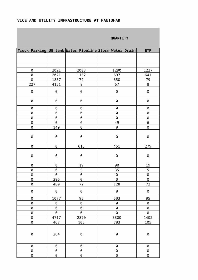
KB: BOQ FOR CIVIL, STRUCTURAL AND INFRASTRUCTURE WORKS FOR MFP SERVICE AND UTILITY INFRASTRUCTURE AT FANIDHAR
QUANTITY
Truck Parking UG tank Water Pipeline Storm Water Drain ETP Canal
0 2021 2008 1290 1227 10200 2021 1152 697 641 00 1887 79 650 79 0
227 4151 8 67 8 1020
0 0 0 0 0 0
0 0 0 0 0 0
0 0 0 0 0 00 0 0 0 0 00 0 0 0 0 00 0 6 49 6 940 149 0 0 0 0
0 0 0 0 0 0
0 0 615 451 279 0
0 0 0 0 0 0
0 0 19 90 19 00 0 5 35 5 00 0 0 0 0 00 396 0 0 0 00 480 72 128 72 0
0 0 0 0 0 0
0 1077 95 503 95 00 0 0 0 0 00 0 0 0 0 00 0 0 0 0 00 4717 2870 3300 1402 00 467 105 703 105 0
0 264 0 0 0 0
0 0 0 0 0 00 0 0 0 0 00 0 0 0 0 0
0 0 0 0 0 00 0 0 0 0 00 0 0 0 0 0
0 97 25 45 14 0
0 0 0 0 0 00 0 0 0 0 0
0 0 0 0 0 0
0 0 0 0 0 00 112 0 0 0 00 0 0 0 0 00 0 0 0 0 0
0 166 0 0 0 0
0 861 0 0 0 0
0 0 0 0 0 00 0 0 0 0 00 288 0 0 0 0
0 0 0 0 0 0
0 3398 0 0 0 00 108 0 0 0 00 331 0 0 0 00 0 0 0 0 00 18 0 0 0 0
1980 0 0 0 0 0
1320 0 0 0 0 0
0 0 0 0 0 00 0 0 0 0 00 0 0 0 0 00 29 0 0 0 00 0 0 0 0 0
0 29 0 0 0 0
0 32 0 0 0 00 0 0 0 0 00 0 0 0 0 0
0 704 0 0 0 0
0 104 0 0 0 00 4515 185 1152 185 00 1184 0 0 0 00 304 0 0 0 00 0 0 0 0 51000 0 0 0 0 00 0 0 0 0 00 1488 0 0 0 0

0 704 0 0 0 0
0 0 0 0 0 0
0 1184 0 0 0 0
0 0 0 0 0 00 0 0 0 0 00 0 0 0 0 00 0 0 0 0 00 60 0 0 0 00 0 0 0 0 00 0 0 0 0 0
0 12 0 1 0 0
0 791 41 216 41 00 2 0 2 0 00 0 0 0 0 00 0 0 0 0 00 0 0 0 0 0
0 0 45 0 50 0
0 0 50 0 55 0
0 0 1 0 0 0
0 0 0 0 0 00 0 0 0 0 00 0 0 0 0 00 0 0 0 0 00 0 0 0 0 00 0 0 0 0 0
0 23 0 0 0 0
0 0 0 0 0 0
0 0 0 0 30 00 0 0 0 20 00 0 0 0 10 00 0 0 0 0 0
0 0 90 0 0 0
0 0 0 0 0 0

0 0 0 11 0 0
0 0 0 31 0 0
0 0 0 62 0 0
0 0 0 28 0 0
0 0 0 14 0 0
0 0 0 0 0 00 0 2 0 0 00 0 0 0 0 0
0 0 2 0 0 0
0 0 0 0 0 00 0 24 0 0 0
0 0 0 0 0 0
0 0 1870 0 0 00 0 2860 260 150 00 0 51 0 0 0
0 0 0 0 0 0
0 0 100 12 0 00 0 0 0 0 00 14 0 0 0 00 24 0 0 0 00 30 0 0 0 00 48 0 0 0 00 5 0 0 0 00 2 0 0 0 0
0 2 0 0 0 0
0 1 0 0 0 00 0 0 0 0 00 0 0 0 0 0
908 0 0 0 0 03300 0 0 0 0 0
0 0 0 0 0 0
2200 0 0 0 0 0

0 0 0 0 0 00 0 0 8 0 00 0 1325 200 0 00 0 360 345 155 00 0 0 915 840 00 0 105 135 265 00 0 0 90 0 00 0 1560 545 1005 00 0 0 110 0 00 0 0 665 515 00 0 0 515 0 00 0 0 375 0 0
660 0 0 0 0 00 0 0 0 0 00 0 0 0 0 00 0 0 0 0 00 0 0 0 0 00 0 0 0 0 00 0 0 0 0 00 0 0 0 0 00 0 0 0 0 00 0 0 0 0 00 0 0 0 0 00 0 0 0 0 00 0 0 0 0 00 0 0 0 0 00 0 0 0 0 00 285 18 96 18 00 285 18 96 18 00 24 0 0 0 00 540 0 0 0 00 319 54 162 54 00 0 0 11 0 00 0 0 0 0 00 0 0 0 0 0
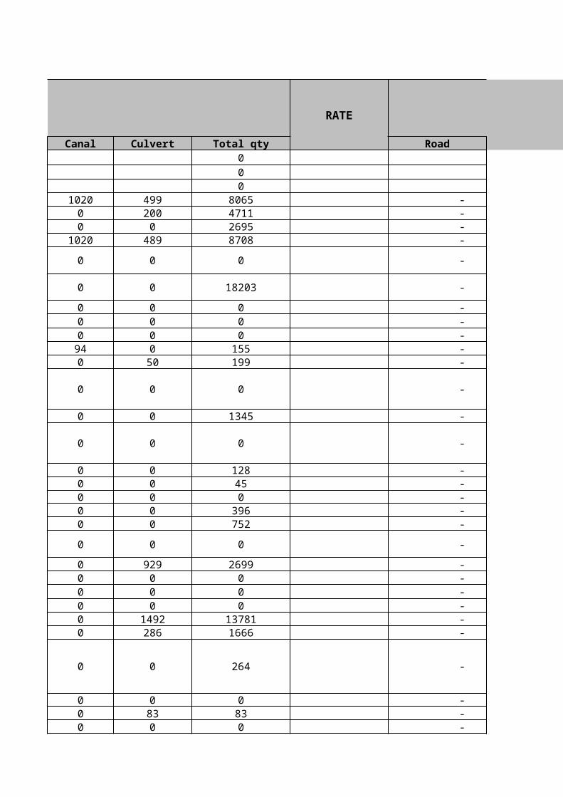
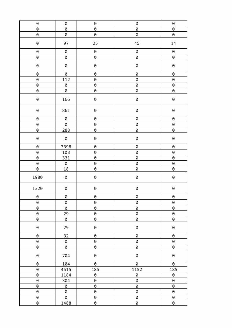
QUANTITY RATE AMOUNT
Culvert Total qty Road Truck Parking 000
499 8065 - - 200 4711 - - 0 2695 - -
489 8708 - -
0 0 - -
0 18203 - -
0 0 - - 0 0 - - 0 0 - - 0 155 - - 50 199 - -
0 0 - -
0 1345 - -
0 0 - -
0 128 - - 0 45 - - 0 0 - - 0 396 - - 0 752 - -
0 0 - -
929 2699 - - 0 0 - - 0 0 - - 0 0 - -
1492 13781 - - 286 1666 - -
0 264 - -
0 0 - - 83 83 - - 0 0 - -

104 104 - - 0 0 - - 0 0 - -
98 279 - -
0 0 - - 0 0 - -
0 0 - -
0 0 - - 0 112 - - 0 0 - - 0 0 - -
0 166 - -
0 861 - -
0 0 - - 0 0 - - 0 288 - -
0 0 - -
0 3398 - - 0 108 - - 0 331 - - 0 0 - - 0 18 - -
0 1980 - -
0 1320 - -
0 0 - - 0 0 - - 0 0 - - 0 29 - - 0 0 - -
0 29 - -
0 32 - - 0 0 - - 0 0 - -
0 704 - -
0 104 - - 0 6037 - - 0 1184 - - 0 304 - - 0 5100 - - 0 0 - - 0 0 - - 0 1488 - -

0 704 - -
1654 1654 - -
0 1184 - -
0 12138 - - 0 0 - - 0 0 - - 0 0 - - 0 60 - - 0 0 - - 0 0 - -
10 23 - -
0 1089 - - 0 4 - - 0 0 - - 0 0 - - 0 0 - -
0 95 - -
0 105 - -
0 1 - -
0 0 - - 0 10 - - 0 6 - - 0 3 - - 0 66 - - 0 25 - -
0 23 - -
0 0 - -
0 30 - - 0 20 - - 0 10 - - 0 0 - -
0 90 - -
0 0 - -

0 11 - -
0 31 - -
0 62 - -
0 28 - -
0 14 - -
0 0 - - 0 2 - - 0 0 - -
0 2 - -
0 0 - - 0 24 - -
0 0 - -
0 1870 - - 0 3270 - - 0 51 - -
0 0 - -
0 112 - - 0 0 - - 0 14 - - 0 24 - - 0 30 - - 0 48 - - 0 5 - - 0 2 - -
0 2 - -
0 1 - - 0 0 - - 0 0 - - 0 14599 - - 0 32124 - - 0 0 - -
0 12714 - -

0 0 - - 0 8 - - 0 1525 - - 0 860 - - 0 1755 - - 0 505 - - 0 90 - - 0 3110 - - 0 110 - - 0 1180 - - 0 515 - - 0 375 - - 0 7867 - - 0 4324 - - 0 28824 - - 0 1441 - - 0 722 - - 0 28824 - - 0 0 - - 0 30 - - 0 4000 - - 0 650 - - 0 640 - - 0 28824 - - 0 0 - - 0 0 - - 0 0 - - 0 417 - - 0 417 - - 0 24 - -
1170 1710 - - 0 589 - - 0 11 - -
114 114 - - 0 0 - -
- -

AMOUNT
UG tank Water Pipeline Storm Water Drain ETP
- - - - - - - - - - - - - - - -
- - - -
- - - -
- - - - - - - - - - - - - - - - - - - -
- - - -
- - - -
- - - -
- - - - - - - - - - - - - - - - - - - -
- - - -
- - - - - - - - - - - - - - - - - - - - - - - -
- - - -
- - - - - - - - - - - -

- - - - - - - - - - - -
- - - -
- - - - - - - -
- - - -
- - - - - - - - - - - - - - - -
- - - -
- - - -
- - - - - - - - - - - -
- - - -
- - - - - - - - - - - - - - - - - - - -
- - - -
- - - -
- - - - - - - - - - - - - - - - - - - -
- - - -
- - - - - - - - - - - -
- - - -
- - - - - - - - - - - - - - - - - - - - - - - - - - - - - - - -

- - - -
- - - -
- - - -
- - - - - - - - - - - - - - - - - - - - - - - - - - - -
- - - -
- - - - - - - - - - - - - - - - - - - -
- - - -
- - - -
- - - -
- - - - - - - - - - - - - - - - - - - - - - - -
- - - -
- - - -
- - - - - - - - - - - - - - - -
- - - -
- - - -

- - - -
- - - -
- - - -
- - - -
- - - -
- - - - - - - - - - - -
- - - -
- - - - - - - -
- - - -
- - - - - - - - - - - -
- - - -
- - - - - - - - - - - - - - - - - - - - - - - - - - - - - - - -
- - - -
- - - - - - - - - - - - - - - - - - - - - - - -
- - - -

- - - - - - - - - - - - - - - - - - - - - - - - - - - - - - - - - - - - - - - - - - - - - - - - - - - - - - - - - - - - - - - - - - - - - - - - - - - - - - - - - - - - - - - - - - - - - - - - - - - - - - - - - - - - - - - - - - - - - - - - - - - - - - - - - - - - - - - - - - - - - - - -

AMOUNT
Canal Culvert Total
- - - - - - - - - - - -
- - -
- - -
- - - - - - - - - - - - - - -
- - -
- - -
- - -
- - - - - - - - - - - - - - -
- - -
- - - - - - - - - - - - - - - - - -
- - -
- - - - - - - - -

- - - - - - - - -
- - -
- - - - - -
- - -
- - - - - - - - - - - -
- - -
- - -
- - - - - - - - -
- - -
- - - - - - - - - - - - - - -
- - -
- - -
- - - - - - - - - - - - - - -
- - -
- - - - - - - - -
- - -
- - - - - - - - - - - - - - - - - - - - - - - -

- - -
- - -
- - -
- - - - - - - - - - - - - - - - - - - - -
- - -
- - - - - - - - - - - - - - -
- - -
- - -
- - -
- - - - - - - - - - - - - - - - - -
- - -
- - -
- - - - - - - - - - - -
- - -
- - -

- - -
- - -
- - -
- - -
- - -
- - - - - - - - -
- - -
- - - - - -
- - -
- - - - - - - - -
- - -
- - - - - - - - - - - - - - - - - - - - - - - -
- - -
- - - - - - - - - - - - - - - - - -
- - -

- - - - - - - - - - - - - - - - - - - - - - - - - - - - - - - - - - - - - - - - - - - - - - - - - - - - - - - - - - - - - - - - - - - - - - - - - - - - - - - - - - - - - - - - - - - - - - - - - - - - - - - - - - - -

KB: BOQ FOR PUMPS & PANEL WORKS FOR EXTERNAL PARK INFRASTRUCTURE AT FANIDHAR
Sr.No.
G.
1.0
1.1,

1.2

2
2.1
2.2
2.3

2.4
3
4
4.1
4.2

4.3
5
5.1
5.2
H.
1
1.1

1.2
1.2.1

1.2.2
2
2.1

2.2
2.3
2.4
3
3.1

KB: BOQ FOR PUMPS & PANEL WORKS FOR EXTERNAL PARK INFRASTRUCTURE AT FANIDHAR
DESCRIPTION
WATER SUPPLY, DRAINAGE, PUMPS & EQUIPMENT
Domestic Water transfer pumping system & Flushing Water Supply Pumping
Water Flow Rate : 10.5 LPS Head : 55 M Purpose: Flushing Water Supply Nos. of Pumps as Set : 03 Nos. ( 02 Nos. working + 1 No. Standby duty assist)
Supply, Installation, Testing And Commissioning Of Compact Self Contained Skid Mounted Level controlled Tank filling system As Follows:
a. In-Line, centrifugal pumps with SS-304 casing and impeller and SS-316 shaft, CI base & head TEFC motor (with mechanical seal)
(Vendor to submit performance curves and technical catalog of the proposed model for review & information)
The pump shall be selected for performance at best efficiency point. However, the pump selection shall be suitable for performance with set point @ + 20% of the rated head.
Complete requirment as per drawing,BOQ,Specification & as directed by EIC/ARCHITECT.
a. External Pump mounted or wall mounted microprocessor PID controller and frequency inverter integrated in a single body or as separate components with pressure sensor transmitter minimum two lined LCD display, diodes to indicate pump ready, pump running and fault and capable to communicate with other controllers following MODBUS-RTU or BACNET Class-2 protocol through RS485 port. System should be capable to compensate for frictional losses at lower flows. All alarms should be displayed in the controller. System should be equipped with dry running protection

Water Flow Rate : 15 LPS Head : 55 M Purpose: Domestic Water Transfer Nos. of Pumps as Set: 04 Nos. ( 3 Nos. working + 1 No. Standby duty assist)
b. Complete (Skid mounted wall mounted / floor mounted) electrical control panel comprising of all accessories such as PLCs, pressure switches, pressure transducers, control wiring and any other necessary imports etc. (list to be provided by the vendor)
c. Precharged diaphragm pressure vessel with food grade membrane, charging connection, connected to outlet header with necessary flanges, gaskets, isolating valves, nuts/bolts etc complete.
d. Set of accessories such as pressure switches, pressure transducers, inter connecting power and control cabling etc. complete
e. Accessories like Strainer,NRVs, isolating valves, SS-304 (non-Magnetic) suction and delivery header, pressure gauge, MS base frame (Synthetic enamel painted over a coat of primer)
a. Complete (Skid mounted wall mounted / floor mounted) electrical control panel comprising of all accessories such as PLCs, pressure switches, pressure transducers, control wiring and any other necessary imports etc. (list to be provided by the vendor)
b. Precharged diaphragm pressure vessel with food grade membrane, charging connection, connected to outlet header with necessary flanges, gaskets, isolating valves, nuts/bolts etc complete.
c. Set of accessories such as pressure switches, pressure transducers, inter connecting power and control cabling etc. complete
d. Accessories like Strainer,NRVs, isolating valves, SS-304 (non-Magnetic) suction and delivery header, pressure gauge, MS base frame (Synthetic enamel painted over a coat of primer)

Submersible Sump PumpsSubmersible Centrifugal Non-clog Drainage Pumps
Vendor to submit proposed pump model with duty curve.
Flow rate : 3.0 LPSHead : 15 Mts Solid Handling : 10-12 MMLocation : Plumbing Plant RoomPurpose : Plant Room drainage MOC : Stainless steel No. of pumps: (1 W + 1S)
Flow rate : 5.0 LPSHead : 25 Mts Solid Handling : 10-25 MMLocation : Sewage & ETP Sump PitPurpose : Sewage & Effluent drainage MOC : Stainless steel No. of pumps: (1 W + 1S)
Flow rate : 2.0 LPSHead : 15 Mts Solid Handling : 10-25 MM
e. External Pump mounted or wall mounted microprocessor PID controller and frequency inverter integrated in a single body or as separate components with pressure sensor transmitter minimum two lined LCD display, diodes to indicate pump ready, pump running and fault and capable to communicate with other controllers following MODBUS-RTU or BACNET Class-2 protocol through RS485 port. System should be capable to compensate for frictional losses at lower flows. All alarms should be displayed in the controller. System should be equipped with dry running protection
Supply, installation, testing and commissioning of continuous duty submersible centrifugal non-clogging drainage pumps complete with 3 phase motor with all necessary protection and mechanical seal etc. Motor shall be 2 Pole. (1W + 1S)Complete requirment as per drawing,BOQ,Specification & as directed by EIC/ARCHITECT.

Location : Sewage & ETP Sump PitPurpose : Sewage & Effluent drainage MOC : Stainless steel No. of pumps: (1 W + 1S)
Flow rate : 6.0 LPSHead : 35 Mts Solid Handling : 10-12 MMLocation : Sump-01 to 06Purpose : Storm Water drainage MOC : Stainless steel No. of pumps: (3W + 1S)
Note
80 mm dia
100 mm dia
Supplying and installing in the sump pit lifting assembly suitable for 2 No. submersible drainage pumps in a sump of overall depth not more than 1.6 m, ready made electro – galvanized MS lifting chain, class C GI pipe header complete with discharge manifold, flanges, tee, elbow etc. complete including GI pipe upto the top of sump and including GI union. The installation shall be complete with all necessary indigenous accessories as required to complete the installation.Complete requirment as per drawing,BOQ,Specification & as directed by EIC/ARCHITECT.
Shop drawing for the installation to be approved by the Project Manager prior to execution.
Providing and fixing in position Class C GI pipe work for all pump suction / discharge line with common header complete with all fittings like elbow, tee, reducer, flange, union etc. conforming to IS:1239 (Part 1) for pipes and IS : 1879 (Part 1 to 10) for fittings including fixing in wall / ceiling / floor level, supported by galvanized clamps, hangers, vertical pipe support etc.Complete requirment as per drawing,BOQ,Specification & as directed by EIC/ARCHITECT.

150 mm dia
100 mm dia
150 mm dia
Total : "G" Carried to Summary
ELECTRICAL INSTALLATION FOR PUBLIC HEALTH ENGG SYSTEM
Note:-
Providing and fixing floating flange EPDM rubber expansion joint with unit control (tie rod & gusset plate) as per manufacturers specifications of standard length complete with all accessories tested to a pressure not less than 15 Kg./sqcm including rubber gaskets, flanges, nuts, bolts & washers etc.Complete requirment as per drawing,BOQ,Specification & as directed by EIC/ARCHITECT.
Electrical panel for Level controlled Domestic water transfer system, & Flushing Water Supply SystemDesign, fabrication as per approved drawings, assembling, wiring, testing at works, packing, supply, installation, testing and commissioning of motor control centres ( MCC). The MCCs shall be fabricated out of 14 gauge CRCA sheet steel in form 3b formation with reinforcement of suitable size angle iron, channel ‘T’ sections irons and/or flats wherever necessary. Cable gland plates shall be provided on top as well as at the bottom of the panels. Panels shall be treated with all anticorrosive process before painting as per specifications with 2 coats of red oxide primer and final approved shade of powder coated paint. 2 Nos. earthing terminals shall be provided for 3 phase, 4 wire, 50 Hz supply system. Lifting hooks shall also be provided in case of large panels. Approval shall be taken for each panel before fabrication. Cadmium Plated hardware shall be used in fabrication of panels.Complete requirment as per drawing,BOQ,Specification & as directed by EIC/ARCHITECT.
The Contractors rate shall be all inclusive for preparing the foundation/plinth required at site for installing the Panels. The plinth shall be casted of PCC in required proportion and the plinth height shall be minimum 275mm above floor level.
MCC - Plant RM-01Incoming315 amps TPN MCCB with the following accessories:
0 - 500 volts 96 x 96 sq mm digital voltmeter with selector switch. Set 1
c. Phase indicating lamps protected by 2 amp SP MCB Set 3
Bus Bar
Outgoing:
0 - 315 amps 96 x 96 sq mm digital ammeter with 315/5 amps 10 VA CL:1 CT’s and selector switch Set 1
350 amps, (25 kA for 1 sec.) Tinned Copper bus bar with colour coded heat shrinkable sleeves for three phase & neutral. Phase bus bar shall have maximum current density of 1.2 amps per sq.mm. and the neutral bus bar of not less than 50% capacity.
a. 3 Nos.40A TPN MPCB outgoing feeders suitable for 3 Nos. 20 HP ( 2 Working + 1 Standby ) out going feeders to Domestic water Transfer Pump. The compartment shall contain CT operated digital electronic ammeter of suitable range with selector switch and indicating lamp with MCBs for `ON'/OFF`TRIP' status of motor.
b. 1 No. 15 amps TPN MCCB outgoing feeders for MCC-Plumbing Plant Room sump pump. The compartment shall contain indicating lamp with MCBs for `ON' indication of the breaker.
c. 4 Nos.25A TPN MPCB outgoing feeders suitable for 4 Nos. 10 HP ( 3 Working + 1 Standby ) out going feeders to Domestic water Transfer Pump. The compartment shall contain CT operated digital electronic ammeter of suitable range with selector switch and indicating lamp with MCBs for `ON'/OFF`TRIP' status of motor.
d. 4 Nos.32A TPN MPCB outgoing feeders suitable for 4 Nos. 5 HP ( 2 Working + 2 Standby ) out going feeders to SPS Pump. The compartment shall contain CT operated digital electronic ammeter of suitable range with selector switch and indicating lamp with MCBs for `ON'/OFF`TRIP' status of motor.

i. 40 TPN MPCB with star delta starter - 2 nos.
ii. 25 TPN MCCB 5 Nos.
Note:
MCC - Plant RM-01 as described above.
Control Panel For Sump PumpMCC - Plumbing Plant room sump pumpIncoming16 Amps TPN MCCB with the following accessories:
c. Phase indicating lamps protected by 2 amp SP MCB Set 3
Bus Bar
Outgoings
e. Spare MCCB’s of following capacities:
f. Necessary cable alleys space for spare switches, internal wiring and copper earthing of all equipment shall also be included. All switch gears/control gears shall be motor duty rating.
All MCCB's / MPCB's to be suitable for motor duty and shall be of 25 kA (Ics=Icu) breaking capacity.The MPCB's/MCCB's selected are as per Type 2 Co-ordination and the rating may vary from Manufacturer to Manufacturer. The supplier should check for the correctness of the same.
Provision shall be made for providing potential free contacts to all pumps starters for connection to building automation system.
a. 0-500 volts 96 x 96 mm square digital electronic voltmeter with selector switch through 415 V/√3:110 V/√3 PT primary and secondary of PT’s shall be protected by 2 amps TP MCB. 1 Set
b. 0-16 amps 96 x 96 mm square digital electronic ammeter with selector switch and 16/5 amps 15 VA CL:1 CTs. 1 Set
16 Amps TPN (10 KA) tinned copper bus bar with colour coded heat shrinkable insulation sleeves.
a. 2 No. 10A TPN MPCBs suitable for 2 Nos. 1.0 KW direct on line starter and outgoing feeders to Sump Pumps ( 1working + 1 standby ). Each compartment shall contain direct operated digital electronic ammeter of suitable range with auto/manual selector switch and indicating lamps with MCB’s and ‘ON/OFF/TRIP’ status of motor

Control Panel for Plumbing Plant room sump pump as described above
MCC - Sewage Pumping Station sump pumpIncoming32 Amps TPN MCCB with the following accessories:
c. Phase indicating lamps protected by 2 amp SP MCB Set 3
Bus Bar
Outgoings
Control Panel for Plumbing Plant room sump pump as described above
Cable & Cable Trays for Plumbing System
b. Necessary cable alleys, internal wiring, and interlocking, earthing for all equipment shall also included
a. 0-500 volts 96 x 96 mm square digital electronic voltmeter with selector switch through 415 V/√3:110 V/√3 PT primary and secondary of PT’s shall be protected by 2 amps TP MCB. 1 Set
b. 0-32 amps 96 x 96 mm square digital electronic ammeter with selector switch and 32/5 amps 15 VA CL:1 CTs. 1 Set
32 Amps TPN (10 KA) tinned copper bus bar with colour coded heat shrinkable insulation sleeves.
a. 2 No. 32A TPN MPCBs suitable for 2 Nos. 5 HP direct on line starter and outgoing feeders to Sump Pumps ( 1working + 1 standby ). Each compartment shall contain direct operated digital electronic ammeter of suitable range with auto/manual selector switch and indicating lamps with MCB’s and ‘ON/OFF/TRIP’ status of motor
b. Necessary cable alleys, internal wiring, and interlocking, earthing for all equipment shall also included
Supplying & laying of following 1100 volt grade XLPE insulated PVC inner sheathed and FRLS PVC outer sheathed aluminium conductor armoured cables as per specification in existing trenches, cable trays, ducts, clamped to wall with suitable clamps including, saddles fixing bolts, connecting testing and commissioning.Complete requirment as per drawing,BOQ,Specification & as directed by EIC/ARCHITECT.

Earthing for Plumbing & System
Total : "H" Carried to Summary
TOTAL SUMMARY
Supplying & laying of following 1100 volt grade PVC insulated copper conductor armoured cables as per specification in existing trenches, cable trays ducts over bed of sand, clamped to wall with suitable clamps, saddles fixing bolts including connecting testing and commissioning.Complete requirment as per drawing,BOQ,Specification & as directed by EIC/ARCHITECT.
Cable end termination of the following aluminium/copper conductor armoured cables of 1100 volt grade including supplying and fixing of bimetallic crimping lugs, double compression glands with earthing facility and cable sockets etc. complete as required.Complete requirment as per drawing,BOQ,Specification & as directed by EIC/ARCHITECT.
Supply and fixing of perforated type GI cable trays with supports, hangers, fasteners of the following sizes as per specification.Complete requirment as per drawing,BOQ,Specification & as directed by EIC/ARCHITECT.
Supply and fixing of following bare GI tapes / wires including all necessary fixing accessories and effecting connections as per specifications.Complete requirment as per drawing,BOQ,Specification & as directed by EIC/ARCHITECT.

KB: BOQ FOR PUMPS & PANEL WORKS FOR EXTERNAL PARK INFRASTRUCTURE AT FANIDHAR
UNIT QUANTITY UNIT RATE TOTAL AMOUNT
Set 1 - -
Nos. 1 -
-

Nos. 1 -
-
Nos. 1 -
-
Set 1 -
-
Set 1 -
- - - -
Set 1 - -
Nos. 1 -
-
Nos. 1 -
-
Set 1 -
-
Set 1 -
-

Nos. 1 -
- - -
-
- - - - - - - -
Set. 3 - - - - - - - -
Set. 2 - - - - -

- - -
Set. 2 - - - - - - - -
Set. 6 - - -
Set 13 -
-
-
-
-
- RM 225 -
- RM 109 -

- RM 55 -
- -
-
- No. 16 -
- No. 16 -
- -


Set 1 - - -
-
-
-
-
-
-
-
-
-
-

-
- Set 5 -
- -
-
-
-
-
-
-
-
-
-
-
- Set 2 -
- - -
Set 1 -
-

Set 1 -
-
Set 1 -
-
Set 1 -
- - -
Set 1 -
-
-

Consultant: VMS Engineering Design Services (P) Ltd
ANNEXURE - ISCOPE OF WORK FOR FIRE FIGHTING SYSTEM
S.No. Work Scope
1 Site office Tenderer scope (M/s Fanidhar will provide space for the same)2 Material security at site till commissioning and handing over Tenderer scope
3 Tenderer scope
4 Installation & commissioning Tenderer scope
5 Tenderer scope
6 Spare Parts Required
7 Tenderer scope
8 Operation & Maintenance manual
9 Shop Drawings & As Built Drawings
10 Tenderer scope
11 Civil Design Reference Drawings and Civil work drawings Tenderer scope
12 Tenderer scope
13 Placement of Equipments & Accessories on its Foundations Tenderer scope
14 On site training of workmen/staff . Tenderer scope
15 In Tenderer scope
16 Government License / Approvals if required In Tenderer scope
17 Tenderer scope
18 Supervision & Project Management at Site Tenderer scope
19 Insurance of Manpower at site as per Prevailing Rules and Regulations Tenderer scope
20 Tenderer scope (as per Client's requirement / Indian law)
21 Tenderer scope (as per Client's requirement / Indian law)
22 Tenderer scope
23 Tenderers scope
24 Tenderer scope even if Minor civil work is not in party scope.
25 Tenderer Scope
26 Tenderers scope
27 Contruction Power & Water for carrying out work on 24 hour basis
28 Tenderers scope
29 Tenderers scope
30 Tenderer Scope
Tenderer Name With Contact Details(Below Detail to be Confirmed by Tenderer)
All Testing Equipment required for Performance Testing and Commissioning .
Insurance during E&C and third party liability , storage and transit insurance
For 1 year normal maintenance( specified List to be submitted by Supplier along with tender and the same would be finalised )
Detailed Shop Drawings with Iso Metrics,Submission Design Calculations, data sheets and other documents
3 sets(1 original+ 2 copy) bound in a standard size folder with indexing and proper labellling. 2 Set in Soft Copy (auto cad / Word / Excel +pdf format)5 sets bound in a standard A1 size in Folder with Indexing. 2 Set in Soft Copy(auto cad+pdf format)
Special Tools & Tackles,Illumination at Site,construction Power,Water ,Compressed Air
Minor Civil Work including Support Grouting, Openings, Anchoring, closing of openings etc.
Any other item which is required for Safe Operation of Plant but not indicated above
Providing Safety Device (PPE) for Contractor's Workman and Staff Working in Plant
Final painting of approved shade of all piping , Valves, supports, vessels and tanks etc. Marking of direction of flows and lableling of piping etc would be done on pipe line
Labelling of all equipment to be done with Flex Boards UV resistant of A4/A3 sizes depenfing on Size of Equipmetn for Rotary or static equipment and Painted on tanks and walls of Tanks for large storgae capacties.
Cleanliness of site / regular shifting of scrap out of M/s Fanidhar premises .ESI ,PF and any other Complaince for working as per Contractors Rule& Regulation Grouting of the Pumps, Equipments, Anchor Fasteners of Supports ,Platform for Clarifier, foundation bolts etc. Manpower as well as material in vendors scope at no extra cost.
All underground piping if required excavation, wrapping coated with bitumen sheet after application of bitumen paint as per IS:10221.
Consumables ,Canteen,Residential, drinking water, site office ,stationary and printing facilities for the workers and employees
Client Will Provide Single Point Power On chargable basis Further shall be scope of Tenderer's scope.
Medical facilities, Tenderer has to maintain proper medical kit and doctor if required Site supervision , safety incharge and labours to carry out works on 24 hour basis with the Prior permiission of Engineer Incharge
Approval For Sub contractor and Engineers to be Deployed at site for erection/comissioning would be taken only after approval from M/s Fanidhar .Proper Saftey Engineer and Store manager to be deployed

Consultant: VMS Engineering Design Services (P) Ltd
Summary of Parts
Part - A FIRE PUMP ROOM_INFRA 1 Lot 0 0
Part - B FIRE PUMP ROOM_CPC 1 Lot 0 0
Part - C FIRE HYDRANT SYSTEM_INFRA 1 Lot 0 0Total_Basic 0 0
Total Amount Supply (INR)
Total Ammount Erection (INR)

VMS Engineering Design Services (P) Ltd.
PROJECT: M/s. FANIDHAR MEGA FOOD PARK
Sr.No. Description Qty Unit
Tenderer NameSupply Erection
Part - A Fire Pump Room_INFRA
1 1 Lot 0 0
2 1 Lot 0 0
3 1 Lot 0 0
4 1 Lot 0 0
5 1 Lot 0 0
6 1 Lot 0 0
7 0 0
Size 0 0
250 NB 10 Mtrs 0 0200 NB 18 Mtrs 0 0150 NB 20 Mtrs 0 0
65 NB 5 Mtrs 0 050 NB 10 Mtrs 0 025 NB 10 Mtrs 0 0
8 0 0
Size 0 0200 NB 4 Nos 0 0
65 NB 1 Nos 0 0
9 0 0
Size 0 00 0
150 NB 4 Nos 0 050 NB 1 Nos 0 0
10 0 0
Size 0 0150 NB 2 Nos 0 0
50 NB 1 Nos 0 00 0
11 0 0
Size 0 0200 NB 2 Nos 0 0
65 NB 1 Nos 0 0
12 0 0
Size 0 050 NB 1 Nos 0 025 NB 3 Nos 0 0
13 0 0
Size 0 0
Unit Basic Rate ( )₹
Total Amount Supply
( )₹
Unit Basic rate Erection
( )₹
Total Amount Erection
( )₹
Supply, installation, testing, & commissioning of Diesel engine driven Stand by Pump suitable for automatic operation consisting of the following.Back Pull out centrifugal type pump complete for delivery of 171 m3/hr against a total head of 100 metres with bronze impeller, shaft SS complete with mechanical seal with Complete accessories like Earthing, Battery, Charging system, Local Push Button, Cabling between Panel and Diesel Engine. Including Radiator cooled Diesel Engine developing suitable head for the above pump complete with Diesel tank of Min 2 Hrs consumption. Conforming to requirements of IS.
Supply installation testing and commissioning of diesel exhaust pipe of 65 NB & Exhaust Silencer complete with Supporting, Insulation, adhesive, Cladding and Fixing & wire mesh.
Supply, installing, testing, & commissioning of Electric motor driven Main Pump suitable for automatic operation consisting of the following (as per specification). Back Pull out centrifugal type pump complete for delivery of 171 m3/hr against a total head of 100 metres with bronze impeller, shaft SS complete with mechanical seal with Complete accessories like Earthing, Local Push Button, Cabling between Panel and Pump Motor. Including Squirrel cage induction motor. Conforming to requirements of IS.
Supply, installing, testing, & commissioning of electric motor driven Jockey Pump suitable for automatic operation consisting of the following (as per specification). Electric driven automatic pressurisation pump set consisting of the following. Vertical In line, centrifugal Multistage Jockey pump complete for delivery of 10.8 m3/hr against a total head of 100 metres with SS impeller complete with mechanical seal with Complete accessories. Squirrel cage induction motor suitable for above pump.
Providing & fixing , testing & commissioning of cubical type floor mounted Control / Starter Panel for Fire Pumps fabricated FROM 16G M.S sheet dully painted with stove enamelled finish of approved shade and comprising of all Incomers ,MCCB Switch Unit, Isolation MCCB Switch unit of Suitable Capacity for each Pump, Fully Automatic Star Delta Starter for each Electric Pump, Over load relays,Timers,Indicating Lamps, Panel type Ammeter & Voltmeters, incoming Power Cables, Control Cables of suitable Size, Suitable size of PVC Armoured FLRS (Outer Shieth)Cable from Main Panel to Motors Complete with Glands. The Panel shall be complete in all respect to make the Fire Hydrant fully Functional.
Supply, Installation, testing & commissioning of Air vessel of 450 mm dia. 1.5 meter long made from M.S with 25mm-dia spring-loaded air release valve, safety valve(PRV), 25mm drain valve.
Supply, Installation, testing & commissioning of M.S. pipe heavy duty Class ‘C’ ISI marked as per IS: 1239/IS 3589 Part-I & II including cutting, screwing, welding etc. with all fittings as tees, elbows, reducers, flanges, U Bolts, wire ropes etc. painting with one coat of primer and two coats of synthetic enamel paint of colour code of RAL-3000.
Supply, Installation, testing & commissioning ISI marked C.I Sluice valve of PN 1.6 Rating of the following size complete with bolts, nuts, washers and inserted rubber gaskets as required. As per IS:14846
Supply, Installation, testing & commissioning ISI marked C.I Butterfly valve of PN 1.6 Rating of the following size complete with bolts, nuts, washers and inserted rubber gaskets as required (The Valves shall have additional flange pair with distance Piece. The Valves 150NB & above 150NB shall be Manual Gear Operated Type) As per IS:13095
Supply, Installation, testing & commissioning ISI marked C.I Dual Plate type Non- Return valve flanged end Rubber seated PN 1.6 rating with matching Flanges , Nut, bolts, washer & Gaskets. As per IS:5321
Supply, installation, testing and commissioning of "Y" type Flanged Strainer with 50 micron of at least 10 times pipe area with flanged inlet and outlet, PN 16 complete as required. With matching Flanges, Nut, bolts, washer & Gaskets.
Supply, installation ,testing & commissioning of Ball Valves of #150, 3 Piece Design ,Body Cast Carbon Steel ,Trim and Ball SS410 , Seat PTFE. Threaded End / Flanged End. As per IS:17292
Supply, installation ,testing & commissioning of Air release valve body brass complete with all accessories.

VMS Engineering Design Services (P) Ltd.
PROJECT: M/s. FANIDHAR MEGA FOOD PARK
Sr.No. Description Qty Unit
Tenderer NameSupply Erection
Unit Basic Rate ( )₹
Total Amount Supply
( )₹
Unit Basic rate Erection
( )₹
Total Amount Erection
( )₹
25 NB 2 Nos 0 0
14 5 Nos 0 0
15 4 Nos 0 0
16 800 Kg 0 0
17 0 0
Size 0 0150 MM 1 Nos 0 0
0 0
Supply, Installation, testing & commissioning of 100 mm dial size 0 to 16 Kg/cm2 range, pressure gauges with all accessories like niddle valve etc. As per IS:3624Supply, Installation, testing & commissioning of Pressure Switches for pressure range of 0 to 16 Kg/cm2 with all accessories like niddle valve etc.Structural Steel of suitable sizes for supoorting of over ground pipes in pump house with application of primer and painting. Price shall include for anchor bolts & all fastening materialsSupply,installation ,testing & commissioning of Fire Pumps Test Meter Body ASTM A 53 along with all accessories like control valve, hose, 150mm size dial

VMS Engineering Design Services (P) Ltd.
PROJECT: M/s. FANIDHAR MEGA FOOD PARK
Sr.No. Description Qty Unit
Tenderer NameSupply Erection
Unit Basic Rate ( )₹
Total Amount Supply
( )₹
Unit Basic rate Erection
( )₹
Total Amount Erection
( )₹
TOTAL PART-A 0 0
Part - B Fire Pump Room _CPC
18 1 Lot 0 0
19 1 Lot 0 0
20 1 Lot 0 0
21 1 Lot 0 0
22 1 Lot 0 0
23 1 Lot 0 0
24 0 0
Size 0 0300 NB 8 Mtrs 0 0250 NB 18 Mtrs 0 0200 NB 18 Mtrs 0 0150 NB 12 Mtrs 0 0
65 NB 5 Mtrs 0 0
50 NB 8 Mtrs 0 0
25 NB 8 Mtrs 0 0
25 0 0
Size 0 0250 NB 4 Nos 0 0
65 NB 1 Nos 0 0
26 0 0
Size 0 0200 NB 3 Nos 0 0150 NB 2 Nos 0 0
50 NB 1 Nos 0 0
27 0 0
Size 0 0200 NB 2 Nos 0 050 NB 1 Nos 0 0
0 0
28 0 0
Size 0 0
250 NB 2 Nos 0 0
65 NB 1 Nos 0 0
29 0 0
Size 0 050 NB 1 Nos 0 025 NB 3 Nos 0 0
30 0 0Size 0 0
25 NB 2 Nos 0 0
31 5 Nos 0 0
32 4 Nos 0 0
33 800 Kg 0 0
Supply, installation, testing, & commissioning of Diesel engine driven Stand by Pump suitable for automatic operation consisting of the following.Back Pull out centrifugal type pump complete for delivery of 200 m3/hr against a total head of 88 metres with bronze impeller, shaft SS complete with mechanical seal with Complete accessories like Earthing, Battery, Charging system, Local Push Button, Cabling between Panel and Diesel Engine. Including Radiator cooled Diesel Engine developing suitable head for the above pump complete with Diesel tank of Min 2 Hrs consumption. Conforming to requirements of IS.
Supply installation testing and commissioning of diesel exhaust pipe of 65 NB & Exhaust Silencer complete with Supporting, Insulation, adhesive, Cladding and Fixing & wire mesh.
Supply, installing, testing, & commissioning of Electric motor driven Main Pump suitable for automatic operation consisting of the following (as per specification). Back Pull out centrifugal type pump complete for delivery of 200 m3/hr against a total head of 88 metres with bronze impeller, shaft SS complete with mechanical seal with Complete accessories like Earthing, Local Push Button, Cabling between Panel and Pump Motor. Including Squirrel cage induction motor. Conforming to requirements of IS.
Supply, installing, testing, & commissioning of electric motor driven Jockey Pump suitable for automatic operation consisting of the following (as per specification). Electric driven automatic pressurisation pump set consisting of the following. Vertical In line, centrifugal Multistage Jockey pump complete for delivery of 10.8 m3/hr against a total head of 88 metres with SS impeller complete with mechanical seal with Complete accessories. Squirrel cage induction motor suitable for above pump.
Providing & fixing , testing & commissioning of cubical type floor mounted Control / Starter Panel for Fire Pumps fabricated FROM 16G M.S sheet dully painted with stove enamelled finish of approved shade and comprising of all Incomers ,MCCB Switch Unit, Isolation MCCB Switch unit of Suitable Capacity for each Pump, Fully Automatic Star Delta Starter for each Electric Pump, Over load relays,Timers,Indicating Lamps, Panel type Ammeter & Voltmeters, incoming Power Cables, Control Cables of suitable Size, Suitable size of PVC Armoured FLRS (Outer Shieth)Cable from Main Panel to Motors Complete with Glands. The Panel shall be complete in all respect to make the Fire Hydrant and sprinkler system fully Functional.
Supply, Installation, testing & commissioning of Air vessel of 450 mm dia. 1.5 meter long made from M.S with 25mm-dia spring-loaded air release valve, safety valve(PRV), 25mm drain valve.
Supply, Installation, testing & commissioning of M.S. pipe heavy duty Class ‘C’ ISI marked as per IS: 1239/IS 3589 Part-I & II including cutting, screwing, welding etc. with all fittings as tees, elbows, reducers, flanges, U Bolts, wire ropes etc. painting with one coat of primer and two coats of synthetic enamel paint of colour code of RAL-3000.
Supply, Installation, testing & commissioning ISI marked C.I Sluice valve of PN 1.6 Rating of the following size complete with bolts, nuts, washers and inserted rubber gaskets as required. As per IS:14846
Supply, Installation, testing & commissioning ISI marked C.I Butterfly valve of PN 1.6 Rating of the following size complete with bolts, nuts, washers and inserted rubber gaskets as required (The Valves shall have additional flange pair with distance Piece. The Valves 150NB & above 150NB shall be Manual Gear Operated Type) As per IS:13095
Supply, Installation, testing & commissioning ISI marked C.I Dual Plate type Non- Return valve flanged end Rubber seated PN 1.6 rating with matching Flanges , Nut, bolts, washer & Gaskets. As per IS:5321
Supply, installation, testing and commissioning of "Y" type Flanged Strainer with 50 micron of at least 10 times pipe area with flanged inlet and outlet, PN 16 complete as required. With matching Flanges, Nut, bolts, washer & Gaskets.
Supply, installation ,testing & commissioning of Ball Valves of #150, 3 Piece Design ,Body Cast Carbon Steel ,Trim and Ball SS410 , Seat PTFE. Threaded End / Flanged End. As per IS:17292
Supply, installation ,testing & commissioning of Air release valve body brass complete with all accessories.
Supply, Installation, testing & commissioning of 100 mm dial size 0 to 16 Kg/cm2 range, pressure gauges with all accessories like niddle valve etc. As per IS:3624Supply, Installation, testing & commissioning of Pressure Switches for pressure range of 0 to 16 Kg/cm2 with all accessories like niddle valve etc.Structural Steel of suitable sizes for supoorting of over ground pipes in pump house with application of primer and painting. Price shall include for anchor bolts & all fastening materials

VMS Engineering Design Services (P) Ltd.
PROJECT: M/s. FANIDHAR MEGA FOOD PARK
Sr.No. Description Qty Unit
Tenderer NameSupply Erection
Unit Basic Rate ( )₹
Total Amount Supply
( )₹
Unit Basic rate Erection
( )₹
Total Amount Erection
( )₹
34 0 0
Size 0 0150 MM 1 Nos 0 0
0 0TOTAL PART-B 0 0
Part - C Fire Hydrant System_INFRA
35
Size200 NB 110 Mtrs 0 0150 NB 3200 Mtrs 0 0
80 NB 50 Mtrs 0 0
36 0 0
Size 0 0150 NB 900 Mtrs 0 0
37 0 0
200 NB 100 Mtrs 0 0150 NB 100 Mtrs 0 0
38 49 Nos 0 0
0 0
39 1500 Kg. 0 0
0 0
40 1000 M3 0 0
0 0
41 0 0
Size 0 0200 NB 3 Nos 0 0150 NB 51 Nos 0 0
0 0
42 0 0
150 NB 40 Nos 0 0
43 0 0
Size 0 0200 NB 1 Nos 0 0150 NB 1 Nos 0 0
0 044 0 0
Size 0 025 MM 2 Nos 0 0
45 49 Nos 0 00 0
46 49 Nos 0 0
47 98 Nos 0 0
48 4 Nos 0 0
0 0
49 2 Nos 0 0
0 050 25 Sets 0 0
0 0
51 Obtaining approval on entire Fire Protection, Extinguisher and detection system from Local Fire authority. 1 Nos 0 0
0 0TOTAL PART-C 0 0
Supply,installation ,testing & commissioning of Fire Pumps Test Meter Body ASTM A 53 along with all accessories like control valve, hose, 150mm size dial
Supply, Installation, testing & commissioning of M.S. pipe heavy duty Class ‘C’ ISI marked as per IS: 1239/IS 3589 Part-I including cutting, screwing, welding etc. with all fittings as tees, elbows, reducers, flanges, U Bolts, wire ropes etc. painting with one coat of primer and two coats of synthetic enamel paint of shade RAL-3000. (Above ground)
Supply, Installation, testing & commissioning of M.S. pipe heavy duty Class ‘C’ ISI marked as per IS: 1239/IS 3589 Part-I including cutting, screwing, welding etc. with all fittings as tees, elbows, reducers, flanges, U Bolts etc.Painting with one coat of primer and two coats of synthetic enamel paint of approved shade & wrapping with 4 mm thick anti corrosive tape on underground pipes. (Under Ground)
Supply, Installation, testing & commissioning of S.S. 304 ERW pipe SCH 10,Stainless Steel pipes ,with Welded fittings suitable for FIRE water supply capable to withstand working pressure 10bar, such as sockets, bends, elbows, tees, reducers, unions,Flanges (class 150) etc. necessary adapters (Under Ground) Flow direction marking with FIRE RED colour Painting with one coat of primer and two coats of synthetic enamel paint of approved shade & wrapping with 4 mm thick anti corrosive tape on underground pipes
Supply, Installation, testing & commissioning of single headed SS 304, ISI mark oblique pattern hydrant landing valve with 80mm diameter flanged inlet & 63 mm instantaneous type female out let with SS 304 blank cap- chain spring release type lug and accessories as per IS: 5290- 1993 (Type ‘A’) (For External)
Structural Steel of suitable sizes for supporting of over Hydrant System, cabinets etc. with application of primer and painting. Price shall include for supports, anchor bolts and all fastening material.
Excavation & Back Filling with watering, Compaction and sand badding minimum 50mm above the pipe height and the Testing for Compaction shall be done as per procedure given in tender.
Supply, Installation, testing & commissioning ISI marked C.I Butterfly valve of PN 1.6 Rating of the following size complete with bolts, nuts, washers and inserted rubber gaskets as required (The Valves shall have additional flange pair with distance Piece. The valves shall be Manual Gear Operated Type) As per IS:13095
Supply, Installation, testing & commissioning ISI marked C.I Butterfly valve of PN 1.6 Rating of the following size complete with bolts, nuts, washers and inserted rubber gaskets as required (The Valves shall have additional flange pair with distance Piece. The valves shall be Manual Gear Operated Type) As per IS:13095 With Locking system (For plot tapping)
Supply, Installation, testing & commissioning ISI marked C.I Sluice valve of PN 1.6 Rating of the following size complete with bolts, nuts, washers and inserted rubber gaskets as required. As per IS:14846
Supply, installation ,testing & commissioning of Air release valve body brass complete with all accessories.
Supply, Installation & testing of SS 63mm dia branch pipe as per ISI specification. As per IS:903.
Supply & Installation of weather proof outdoor type M.S. hose cabinet fabricated from 16g M.S sheet with full front glass door and locking arrangement suitable to accommodate , 2 no of 15 meter long hose pipe and one branch pipe. It should be painted with one coat of primer and two coat of synthetic enamel paint. Size of box - 750 X 250 X 600
Supply, Installation, testing & commissioning 63mm dia 15mtr long reinforced rubber lined hose pipe confirming to IS: 636-1962 PART-A with SS male and female coupling, wire complete. As per IS:903 & IS: 636.Supply,Installatation,Testing & Commissioning of SS 4 way fire brigade in let connection with 63mm instantaneous coupling with Isolation Valve, plug, cap, chain, inbuilt NRV, complete in all respect. As per IS:904
Supply, Installation, testing & commissioning of 100 mm dia size SS 2 way Drawl off connection with 63mm instantaneous Coupling with Plug, Cap,chain, foot valve, complete in all respect.
Supply & Installation of Fire Bucket with Canopy and Stand- 9 Liters Capacity (4 Buckets/Set). As per IS:2546

Consultant: VMS Engineering Design Services (P) Ltd
TECHNICAL SPECIFICATION FOR FIRE HYDRANT SYSTEM
Sr.No. Item Description Tag No. Item Specification
1 ---- General
Tenderer Name With Contact Details(Below Details Confirmation /
Specification by Tenderer)
GENERAL (APPLICABLE FOR ALL SYSTEMS)
Scope includes Design, Supply, installation, testing, commissioning and approval from client, statutory and insurance authorities, maintenance of the system in full working condition for a period of one year.
The specification and other documents shall be read in conjunction with this material specification and BOM and complied with.
The general specifications, safety, installation procedures, environmental protection procedures etc. are to be considered across all systems, unless specifically governed by codes, standards and specifications.
The rates to include cutting, welding, fixing on pipe pedestals / walls / columns / ceiling / trenches, marking, testing, etc. The quoted rate shall also include for chasing / chipping walls, making core cutting / holes in walls / floor and making them good with filler material and finished in cement mortar, providing 50 mm nominal dia raise in floor by concrete to install floor anchored pedestals etc. complete.
The rates to include connecting to fire protection system of water based and electrical systems, providing necessary flow calculations, connection to other electrical / fire / process panels, programming them, etc. complete
System with accessories, pipes, forged fittings, threaded fittings, structural supports, cable trays, paint, coating and wrapping, hydrant and hydrant accessories, isolation valves, pipe fittings, wire rope supports, Threaded rod supports, Extinguishers shall be as per IS Standard & fire alarm system and accessories, etc. shall be FM approved & UL certified.

Consultant: VMS Engineering Design Services (P) Ltd
TECHNICAL SPECIFICATION FOR FIRE HYDRANT SYSTEM
Sr.No. Item Description Tag No. Item SpecificationTenderer Name With Contact Details
(Below Details Confirmation / Specification by Tenderer)
2 ------ Pipes conforming to IS: 1239/IS 3589 Heavy Grade.
The pipes and fittings to be cleaned thoroughly of surface contaminants like Oil, Grease etc. Two coats of zinc rich Red-Oxide Zinc Chromate primer of 40 microns DFT each followed subsequently by two coats of Synthetic Enamel Paint of minimum 30 microns DFT each. Valves and other accessories to be painted as per the manufacturers specifications and touchup at site as required.The color shade for pipelines shall be Fire Red, valves and other equipment can be to manufacturers standard color / black and for the Electrical Equipment shall be Siemens grey / Fire Red.Galvanised materials like threaded rods, anchor fasteners, Universal clamps etc., need not be painted.
The underground MS C Class Heavy duty pipes shall be coated By 4 MM Thk anti Corrosive tape with proper overlapping and holiday testing
Wrapping & Coating to consist 1 layer of 4 mm thick wrapping as available, along with primer etc. complete.
The excavation shall be done to such depth that the Top of the Pipe shall be minimum 1 m below the FGL at all horizontal stretches or of depth as required for the level of the pipe. Excavation, back Filling with Identification / Caution Tape, Compaction and sand bedding minimum 50mm above & below the pipe height and the Testing for Compaction shall be done
PIPING, FITTING AND GENERAL PARTICULARS
Pipes up to 150 mm nominal dia of MS Finish conforming to IS: 1239 Part-1 Heavy Grade. Pipes above 150 mm nominal dia to be of MS Finish to IS:3589, FE 330, of minimum thickness 6.3 mm nominal dia, ERW, ends Plain
Yard piping (underground and aboveground) shall be of welded/ threaded / flanged construction.

Consultant: VMS Engineering Design Services (P) Ltd
TECHNICAL SPECIFICATION FOR FIRE HYDRANT SYSTEM
Sr.No. Item Description Tag No. Item SpecificationTenderer Name With Contact Details
(Below Details Confirmation / Specification by Tenderer)
For underground piping welded fittings are allowed with specification as indicated below.
Threaded Rods to be made from MS Bright Bar(round) equivalent to ASTM A-36 Grade 4.8
Fittings from 15 mm nominal dia to 65 mm nominal dia to be socket welded / socket threaded to ASTM A 105, dimensioned to ANSI B 16.11 3000 lb forged. Fittings above 65 mm nominal dia up to 150 mm nominal dia to be butt-welded to ANSI B 16.25, MOC to ASTM A 234 Gr. WPB and dimensioned to IS:1239 Heavy Gauge. Fittings above 150 mm nominal dia can be fabricated at site from pipe size of same thickness or can be pre-manufactured butt-welded fittings.
For Aboveground / Overhead piping welded fittings are allowed with specification as indicated below.
Fittings from 15 mm nominal dia to 65 mm nominal dia to be socket welded / socket threaded to ASTM A 105, dimensioned to ANSI B 16.11 3000 lb forged. Fittings above 65 mm nominal dia up to 150 mm nominal dia to be butt-welded to ANSI B 16.25, MOC to ASTM A 234 Gr. WPB and dimensioned to IS:1239 Heavy Gauge. Fittings above 150 mm nominal dia can be fabricated at site from pipe size of same thickness or can be pre-manufactured butt-welded fittings.
All Support Accessories like the Universal Clamp, U-Bolt, G-Clamp etc. shall be made from IS-2062 grade A steel. Finish to be zinc plating to min 8 to 10 microns / hot dipped galvanised to minimum 86 microns.
The dimensions of the C-Clamp to be selected for proper fitment to the structural members. Hole size to be selected for the dimensions of the threaded rods. All structural members to be suitable for 5 times the weight of water filled pipes + 114 kgs.
Universal Clamps are to be made from Pre-galvanised GI Sheets the coating thickness for which would be 120GSM.
All items that require raw material thickness up to 2.5mm to be made from pre-galvanised GI sheets. Above 2.5mm the raw material to be from HR sheets which are then electrogalvanized(Zinc Plated).
All companion flanges and dummy flanges to be of M.S Butt-welded of MOC Carbon Steel as per ASTM A 105N, Class 150 with dimensions as per ANSI B 16.5.Companion flanges to be of Slip on, Flat face type.

Consultant: VMS Engineering Design Services (P) Ltd
TECHNICAL SPECIFICATION FOR FIRE HYDRANT SYSTEM
Sr.No. Item Description Tag No. Item SpecificationTenderer Name With Contact Details
(Below Details Confirmation / Specification by Tenderer)
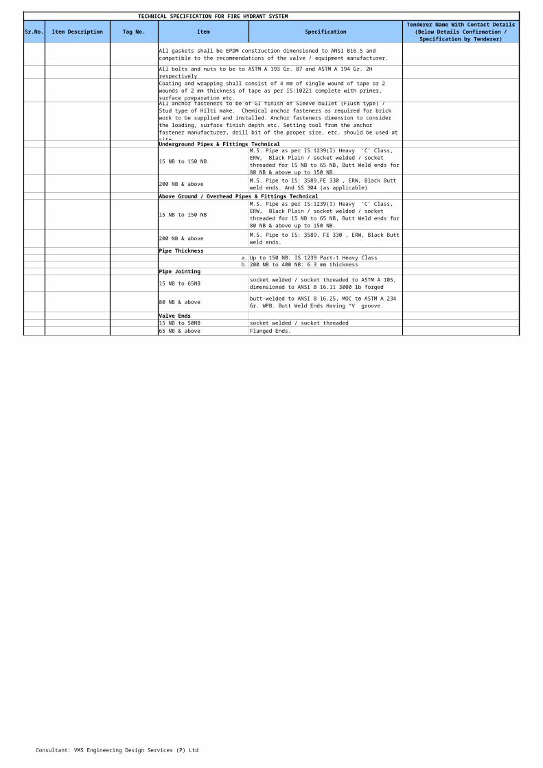
All bolts and nuts to be to ASTM A 193 Gr. B7 and ASTM A 194 Gr. 2H respectively
Underground Pipes & Fittings Technical
15 NB to 150 NB
200 NB & above
Above Ground / Overhead Pipes & Fittings Technical
15 NB to 150 NB
200 NB & above
Pipe Thicknessa. Up to 150 NB: IS 1239 Part-1 Heavy Classb. 200 NB to 400 NB: 6.3 mm thickness
Pipe Jointing
15 NB to 65NB
80 NB & above
Valve Ends15 NB to 50NB socket welded / socket threaded65 NB & above Flanged Ends.
All gaskets shall be EPDM construction dimensioned to ANSI B16.5 and compatible to the recommendations of the valve / equipment manufacturer.
Coating and wrapping shall consist of 4 mm of single wound of tape or 2 wounds of 2 mm thickness of tape as per IS:10221 complete with primer, surface preparation etc.
All anchor fasteners to be of GI finish of Sleeve bullet (Flush type) / Stud type of Hilti make. Chemical anchor fasteners as required for brick work to be supplied and installed. Anchor fasteners dimension to consider the loading, surface finish depth etc. Setting tool from the anchor fastener manufacturer, drill bit of the proper size, etc. should be used at site.
M.S. Pipe as per IS:1239(I) Heavy ‘C’ Class, ERW, Black Plain / socket welded / socket threaded for 15 NB to 65 NB, Butt Weld ends for 80 NB & above up to 150 NB.
M.S. Pipe to IS: 3589,FE 330 , ERW, Black Butt weld ends. And SS 304 (as applicable)
M.S. Pipe as per IS:1239(I) Heavy ‘C’ Class, ERW, Black Plain / socket welded / socket threaded for 15 NB to 65 NB, Butt Weld ends for 80 NB & above up to 150 NB.
M.S. Pipe to IS: 3589, FE 330 , ERW, Black Butt weld ends.
socket welded / socket threaded to ASTM A 105, dimensioned to ANSI B 16.11 3000 lb forged
butt-welded to ANSI B 16.25, MOC to ASTM A 234 Gr. WPB. Butt Weld Ends Having “V” groove.

Consultant: VMS Engineering Design Services (P) Ltd
TECHNICAL SPECIFICATION FOR FIRE HYDRANT SYSTEM
Sr.No. Item Description Tag No. Item SpecificationTenderer Name With Contact Details
(Below Details Confirmation / Specification by Tenderer)
Elbow (R=1.5D) & Reducers
15 NB to 50 NB
65 NB & 150 NB
200 NB & above
Tee
15 NB to 50NB
65 NB & above
Flanges
Gaskets EPDM construction dimensioned to ANSI B16.5Nuts & Bolts ASTM A 193 Gr. B7 and ASTM A 194 Gr. 2H
U Bolts
Surface Preparation
Malleable Iron Fittings confirming to ASTM A 105, dimensioned to ANSI B 16.11 3000 lb forged
Carbon steel toANSI B 16.25, MOC to ASTM A 234 Gr. WPB & IS: 1239(II) heavy duty Dimensions to IS: 1239(II) 1, Butt weld ends.ERW / Seamless
fabricated at site from pipe size of same thickness or can be pre-manufactured butt-welded fittings
Malleable Iron Fittings confirming to ASTM A 105, dimensioned to ANSI B 16.11 3000 lb forged
Carbon steel toANSI B 16.25, MOC to ASTM A 234 Gr. WPB & IS: 1239(II) heavy duty Dimensions to IS: 1239(II) 1, Butt weld ends.ERW / Seamless
Slip on/ blind flanges to be made from MS plates conforming to ASTM A 105N, Class 150 with dimensions as per ANSI B 16.5
One Piece of Design For High Load Capacity.Supplied with four nuts & Shall be Galvanized. Appropriate Span for Safe Installation Support of Pipes As Per Relevant Codes and StandardsPipe Size/U Bolt Dia 15MM - 50MM / ø 8 MM65MM - 100MM / ø 10 MM150MM - 200MM / ø 16 MM
External surface of pipes shall be cleaned manually by wire brushing.

Consultant: VMS Engineering Design Services (P) Ltd
TECHNICAL SPECIFICATION FOR FIRE HYDRANT SYSTEM
Sr.No. Item Description Tag No. Item SpecificationTenderer Name With Contact Details
(Below Details Confirmation / Specification by Tenderer)
Underground Pipe Protection
Above ground Pipe Protection
Hydro Test
3 Sluice Valve ----- Name Sluice ValveModel No. Vendor to SpecifyManufacturer As per approved vendor list Specification Valve design conforming to IS:14846Type Double flanged Sluice Valve(OS & Y Type)Sizes 50 NB & ABOVE
Pressure Rating PN 1.6Material of ConstructionBody Cast IronWedge Cast IronDome Cast IronSpindle SS. as per IS:6603 Gr. 12Cr12Stem Nut Leaded tin Bronze as per IS:318 Gr. LTB-2End Connection IS:1538 Table 4 & 6Hydrostatic Test PressureBody 1.5 times of design pressureSeat 1.1 times of design pressure
4 Butterfly Valve ----- Name Butterfly ValveModel No. Vendor to SpecifyManufacturer As per approved vendor list
Type
Underground pipes to wrapped and coated with 4 mm thick factory made tape as per IS:15337 after the application of primer on clean pipe surface PYPKOTE (4mm) over two coats of primer / Anticorrosive paint.
Two coats of zinc rich Red-Oxide Zinc Chromate primer of 40 microns DFT each followed subsequently by two coats of Synthetic Enamel Paint of minimum 30 microns DFT each.Make - Asian/Goodlas/ Bergeron clean pipe surface. The Colour Shall be RAL-3000 and paint Conform to IS:2932/1964
Pipes shall be hydro tested at Min 1.5 times design pressure for duration of 2 hours minimum.
Butterfly Valve (Wafer Type) Gear Operated with mating flanges, gaskets, one extra flange pair, nut bolts etc. complete.
Consultant: VMS Engineering Design Services (P) Ltd
TECHNICAL SPECIFICATION FOR FIRE HYDRANT SYSTEM
Sr.No. Item Description Tag No. Item SpecificationTenderer Name With Contact Details
(Below Details Confirmation / Specification by Tenderer)
Design Standard Design conforming to IS:13095Dimension Standard ANSI B16.1
Flange Drilling ANSI B16.5Pressure Rating Class 150Model No. Vendor to SpecifyService Water
Op. Temperature – Min/Max (°C) Ambient
Test Pressure, kg(f)/sq.cmBody – (kg/cm²(g)) 1.5 times of design pressureSeat – (kg/cm²(g)) 1.1 times of design pressureEnd Wafer DesignMaterial of ConstructionBody Cast IronShaft SS. as pr IS:6603Disc Cast IronSeat EPDM constuction dimensioned to ANSI B16.5Stem SS 410Gasket Sq. Braided Non-Asbestos
Operation
Hardware Vendor to SpecifyPressure Rating PN 1.6External Surfaces Epoxy Painted
5 Non return Valve ----- Name Non Return ValveModel No. Vendor to SpecifyManufacturer As per approved vendor list Valve Conformation IS:5312Body, Disc C.I , IS:210 Gr. FG200Size 50NB &Above
Hinge Pin High Tensile BrassBody Ring Leaded Tin Bronze, IS:318 LTB 2Pressure Rating PN 1.6Hydraulic Test Pressure Body Test Pressure 1.5 times of design pressureSeat Test Pressure 1.1 times of design pressureEnd connection ANSI B 16.1 CL150
6 Ball valve ----- Name Ball ValveModel No. Vendor to SpecifyManufacturer As per approved vendor list Type Ball Valves Three Piece Design.
150 NB and above shall be gear operated & less than 150 NB shall be manually operated.

Consultant: VMS Engineering Design Services (P) Ltd
TECHNICAL SPECIFICATION FOR FIRE HYDRANT SYSTEM
Sr.No. Item Description Tag No. Item SpecificationTenderer Name With Contact Details
(Below Details Confirmation / Specification by Tenderer)
Design Standard Design conforming to IS:17292Dimension Standard ANSI B16.10Flange Drilling ANSI B16.5Pressure Rating 150#Model No. Vendor to SpecifyService Water
Op. Temperature – Min/Max (°C) Ambient
Vendor to Specify
Test Pressure, Body – (kg/cm²(g) 1.5 times of design pressureSeat-– (kg/cm²(g) 1.1 times of design pressure
End
Material of ConstructionBody ASTM A 216 GR WCBBall ASTM A315 GR CF8MSeat PTFEStem ASTM A 479 Type 316
Rated Pressure of Valve, minimum provided by vendor – (kg/cm²(g))
50 NB & above shall be flanged ended and below 50 NB shall be screwed ended.

Consultant: VMS Engineering Design Services (P) Ltd
TECHNICAL SPECIFICATION FOR FIRE HYDRANT SYSTEM
Sr.No. Item Description Tag No. Item SpecificationTenderer Name With Contact Details
(Below Details Confirmation / Specification by Tenderer)
8 Pressure Gauge ----- Name Pressure GaugeModel No. Vendor to SpecifyManufacturer As per approved vendor list Type Bourdon Type Pressure gauge
As per approved drawings
Accuracy, & FSD ± 1% of FSDSize of dial, mm 100 mmRange, Kg/cm2 0 to 10 Kg/cm2
Yes
Connection size, mm 3/8” BSP (M)
Case construction & material
Phosphor Bronze / Brass
Bourdon Material SS – 316
Yes. Micrometer type provided on the pointer
Coating on movement material BrassOver range protection Blow out disc
Vendor to Specify
Yes. (3-way cock, union nut, nipple & tail piece)
Code to which conforms IS:3624 (CL-I)
Bracing
Provided
Upper range pointer limit stop Provided at 120% of range spanDial White with black lettering in metric units
9 Pressure Switch ----- Name Pressure SwitchMake As per approved vendor listType Bellow TypeModel No. Vendor to SpecifyNumber & location As per approved drawingRange 0 to 10 Kg/sq.cm
Number & Location (Separate sheets may be used if required)
Protection against turbid water Provided
Die cast Aluminium stove enamel black, weather proof with screwed inner of ABS plastic. IP-65
Measuring Element type & Material
External zero adjustment provided?
Gravimetric / Diaphragm seal provided?Provided complete with all accessories?
Connectors between sensing element and socketNeoprene safety diaphragm on the back of the casing.

Consultant: VMS Engineering Design Services (P) Ltd
TECHNICAL SPECIFICATION FOR FIRE HYDRANT SYSTEM
Sr.No. Item Description Tag No. Item SpecificationTenderer Name With Contact Details
(Below Details Confirmation / Specification by Tenderer)
Differential FixedMaximum working pressure 10 barsSensor Phosphor bronze bellows & brass wetted PartsEnclosure Die cast aluminium – weatherproof – IP 66Contact SPDT (1 NO + 1 NC)Contact rating 15 A, 230 V ACProcess Connection ½” NPT (F) with adapter Repeatability ± 0.5 % FSR
9 Air Vessele ----- Name Air VesselType M.S.fabricated diameter 450 mmHeight 1500 mmSheet thcikness Vendor to Specify
accessories
Painting
10 ----- Name Single Headed Hydrant Valve
Make As per approved vendor list Type Single Headed Hydrant ValveDesign Standard IS:5290:1993, Type-A
Size
Approval BISMaterial of Construction
S.S.-304, IS:3444, Gr.-I
Spindle S.S.-304, IS:6528Spring S.S.-304, IS:6528Hand Wheel C.I., IS: 210Coupling Washer Rubber, IS:937,Type A.
Synthetic Rubber
Chain SSBlank Cap S.S.-304, IS:3444, Gr.-I
25mm-dia spring-loaded air release valve, safety valve and gunmetal full way valveOne coat of zinc phosphate primer & two coats of enamel paint, Total dry slim thickness ( DST ) - 100 microns, RAL-300
Single Headed Hydrant Valve
Inlet: 80 mm, OD 200, PCD160, 4holes Ø19mm.Outlet: 63 mm Female Inst. Coupling
Body, Bonnet, Female Inst., Gland Bush, Gland Nut, Check Nut, Valve Seat, Cam tooth, Knurling Bush, Threaded Lug
Flat Washer, Seat Washer, Bonnet Washer

Consultant: VMS Engineering Design Services (P) Ltd
TECHNICAL SPECIFICATION FOR FIRE HYDRANT SYSTEM
Sr.No. Item Description Tag No. Item SpecificationTenderer Name With Contact Details
(Below Details Confirmation / Specification by Tenderer)
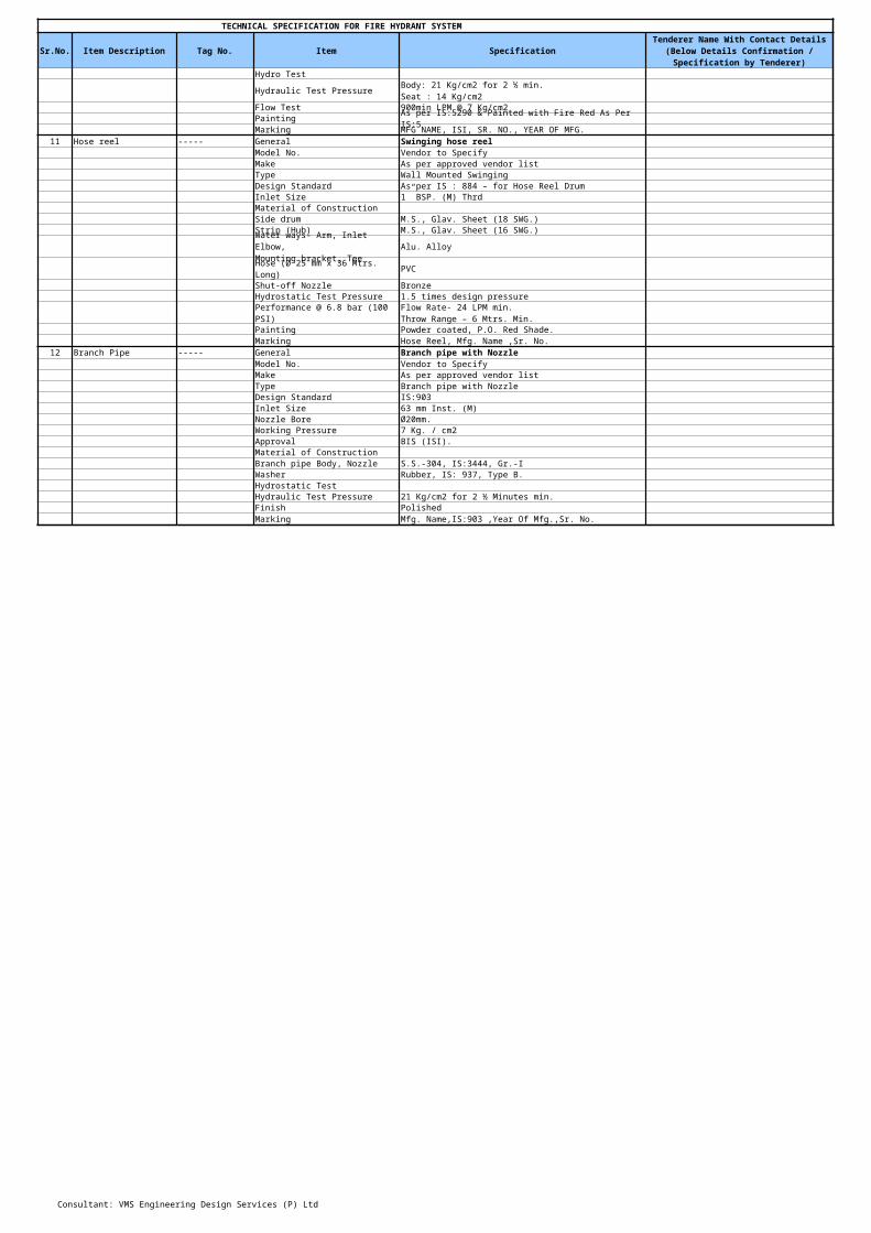
Hydro Test
Hydraulic Test Pressure
Flow Test 900min LPM @ 7 Kg/cm2Painting As per IS:5290 & Painted with Fire Red As Per IS:5Marking MFG NAME, ISI, SR. NO., YEAR OF MFG.
11 Hose reel ----- General Swinging hose reelModel No. Vendor to SpecifyMake As per approved vendor list Type Wall Mounted SwingingDesign Standard As per IS : 884 – for Hose Reel DrumInlet Size 1” BSP. (M) ThrdMaterial of ConstructionSide drum M.S., Glav. Sheet (18 SWG.)Strip (Hub) M.S., Glav. Sheet (16 SWG.)
Alu. Alloy
Hose (Ø 25 mm x 36 Mtrs. Long) PVC
Shut-off Nozzle BronzeHydrostatic Test Pressure 1.5 times design pressure
Performance @ 6.8 bar (100 PSI)
Painting Powder coated, P.O. Red Shade.Marking Hose Reel, Mfg. Name ,Sr. No.
12 Branch Pipe ----- General Branch pipe with NozzleModel No. Vendor to SpecifyMake As per approved vendor list Type Branch pipe with NozzleDesign Standard IS:903Inlet Size 63 mm Inst. (M)Nozzle Bore Ø20mm.Working Pressure 7 Kg. / cm2Approval BIS (ISI).Material of ConstructionBranch pipe Body, Nozzle S.S.-304, IS:3444, Gr.-IWasher Rubber, IS: 937, Type B.Hydrostatic TestHydraulic Test Pressure 21 Kg/cm2 for 2 ½ Minutes min.Finish PolishedMarking Mfg. Name,IS:903 ,Year Of Mfg.,Sr. No.
Body: 21 Kg/cm2 for 2 ½ min.Seat : 14 Kg/cm2
Water ways- Arm, Inlet Elbow,Mounting bracket, Tee
Flow Rate- 24 LPM min.Throw Range – 6 Mtrs. Min.

Consultant: VMS Engineering Design Services (P) Ltd
TECHNICAL SPECIFICATION FOR FIRE HYDRANT SYSTEM
Sr.No. Item Description Tag No. Item SpecificationTenderer Name With Contact Details
(Below Details Confirmation / Specification by Tenderer)
13 Hose Box ----- General Hose boxModel No. Vendor to Specify
Make
Type
Canopy RequiredDesign Standard ISSize 750 X 250 X 600Supporting frame Required From Gr. Lvl.Approval BIS (ISI).Material of ConstructionCabinet 16g M.S sheetHinges S.S.Front Window GlassHandle BrassKey M.S., Galv.Nozzle Clamp M.S.Painting Internally & Externally Painted with fire red color.Marking "FIRE HOSE BOX"
14 RRL Hose ----- Type Reinforced Rubber Lined (RRL)model No. Vendor to SpecifyMake As per approved vendor listSpecification IS:636, Type-AApproval BIS (ISI).Inside diameter 63 mmLength 15 mtrs.
As per approved vendor list (Refer Volume-II of Tender specifications)Wall / Floor Mounted Double Door Type To Accommodate 2 nos. Hoses of 15m & 1no Branch Pipe (spanner & hammer).

Consultant: VMS Engineering Design Services (P) Ltd
TECHNICAL SPECIFICATION FOR FIRE HYDRANT SYSTEM
Sr.No. Item Description Tag No. Item SpecificationTenderer Name With Contact Details
(Below Details Confirmation / Specification by Tenderer)
Burst Pressure 40 Kg/cm2Working Pressure 14 Kg/cm2Proof Pressure 22 Kg/cm2End Connection Pair of male & female instantaneous couplings IS: 903Type of Coupling SS 304 Instantaneous type ISI marked couplingsSize of Coupling 63 mm x 63 mmMarking Mfg. Name,IS:636 ,Year Of Mfg.,Sr. No.
16 ----- Type Four Way Fire brigade Inlet
Model No. Vendor to SpecifyMake As per approved vendor listSpecification IS:904Inlets 63 mm male instantaneous coupling with NRV
Outlet details
Isolation Valves & NRV Required on InletMaterial of ConstructionBody C.I. IS: 210NRV male part, Valve G.M., IS: 318, LTB-2Spring Phosphor bronze IS: 7608Seat Washer Rubber IS: 937Blank Cap Rubber IS: 937Hydrostatic Pressure Test At 21 Kg/cm2
Painting
Four Way Fire Brigade Connection
Flange O.D. 280 mm, PCD 240 mm, 8 holes of 22 mm diameter.
Each Breeching will be painted with 2 coats of fire red paint shade number 536 of IS: 5 over single coat of primer. The paint shall conform to IS: 2932.
Consultant: VMS Engineering Design Services (P) Ltd
TECHNICAL SPECIFICATION FOR FIRE HYDRANT SYSTEM
Sr.No. Item Description Tag No. Item SpecificationTenderer Name With Contact Details
(Below Details Confirmation / Specification by Tenderer)
Marking
17 Drawl Off Point ----- Name Drawl Off Point
Manufacturer
Model No. Vendor to SpecifySpecification IS:902Outlet 100 mm male coupling
Inlet details
Material of ConstructionBody C.I. IS: 210Spring S.S, IS:6528Seat Washer Rubber IS: 937Blank Cap Rubber IS:937Hydrostatic Pressure Test At 21 Kg/cm2Make for Foot valve Normex / Kirloskar
Painting
Marking Each breeching shall be clearly and permanently marked.
i). Manufacturers name or trademark
18 ----- Specification IS:15337
Thickness/width/length 4 mm/250mm/10000mmHeat resistance Should not drip @ 100 Deg CTensile strength 300N/5 Cm & 100N/Cm cross wise
19 Pump Control Panel ----- General
Each breeching shall be clearly and permanently marked.i). Manufacturers name or trademark
As per approved vendor list (Refer Volume-II of Tender specifications)
Flange O.D. 200 mm, PCD 160 mm, 4 holes of 19 mm diameter.
Each Breeching will be Painted with 2 coats of fire red paint shade number 536 of IS: 5 over single coat of primer. The paint shall conform to IS: 2932.
Wrapping & coating material for under ground protection

Consultant: VMS Engineering Design Services (P) Ltd
TECHNICAL SPECIFICATION FOR FIRE HYDRANT SYSTEM
Sr.No. Item Description Tag No. Item SpecificationTenderer Name With Contact Details
(Below Details Confirmation / Specification by Tenderer)
Indicating lights.Isolation MCCB switch unit. For each main Pumps.One MCCB. For Jockey pump
20 Air release Valve ----- Name Air release valveModel No. Vendor to specifyManufacturer As per approved vendor listPressure rating PN 10End Connection ThreadedSize 25 mmType single ball typeMaterial of ConstructionBody Brass alloycap Brass alloyFloat SS 410Internals SS 410
Supply, Installation, testing & commissioning of Motor Control centre with Diesel Engine Control Panel and Battery Charger (The Panel shall be suitable to operate all three pumps in Auto mode and it should have compatibility with diesel engine driven pump & battery system) fabricated from 16G (2 mm min) M.S sheet dully painted with stove enamelled finish of approved shade and comprising of –
Suitable size incoming system, MCCB switch unit. Bus bar voltmeter selector switch and
Fully automatic star delta starters suitable for Motors with overload relay, timer, push buttons and auto manual selector switch.
All in coming power & control wires/ cable of suitable size within the panel and from panel to motors, pressure switches, etc. including glands and termination within fire pump house and earthling as per specification, Suitable PVC armoured cable from main panel to motors with proper termination and required earthing for all three Pump’s Pri-movers and panels.
Earthing, Hooter, Cable Tray, Power & Control Copper Cables of suitable size between Panel, Motors & Engine. The Panel shall be complete in all respect to make the Fire Hydrant & Sprinkler system fully functional.

VMS Engineering & Design Services (P) Ltd.
Electric motor driven pump_INFRA Electric motor driven pump_CPC Jockey Pump_INFRA
Sr No Parameter Units Required Data Offered Data Remarks Required Data Remarks Required Data Offered Data Remarks
A Pumps
A.01.00 Performance Data
A.01.01 Type of Pump End Suction pump End Suction pump Vertical inline pump
A.01.02 Service (Liquid to be handled) fire water fire water fire water
A.01.03 Location of pump Indoor Indoor Indoor
A.01.04 Quantity (total) 1 1 1A.01.05 Operating regime Continous Continous Continous
A.01.06 Rated flow m3/h 171 200 10.8
A.01.07 Rated head( calculated) mWC 100 88 100
A.01.08 % Min 60% Min 60%
A.01.09 Min 60% Min 60% vendor to specify
A.01.10 Vibration Level (peak to peak) As per HIS As per HIS As per HIS
A.01.11dBA
85dBA 85dBA 85dBA
A.02.00 General
A.02.01 Manufacturer (pump/motor)As per approved vendor list As per approved vendor list As per approved vendor list
A.02.02 Place of Manufacture vendor to specify vendor to specify vendor to specify
A.02.03 Model No. of the pump/motor selected vendor to specify vendor to specify vendor to specify
A.02.04 Design code vendor to specify vendor to specify vendor to specify
A.02.05 Performance & testing code ISO 9906 ISO 9906 ISO 9906
A.03.00 Other Operating Data
A.03.01 Pump rated speed rpm 2900 2900 2900
A.03.02 Max. flow rate m3/h vendor to specify vendor to specify vendor to specify
A.03.03 Min. flow rate m3/h vendor to specify vendor to specify vendor to specify
A.03.04 TMH (at minimum allowable flow) mWC vendor to specify vendor to specify vendor to specify
A.03.05 TMH (at maximum allowable flow) mWC vendor to specify vendor to specify vendor to specify
A.03.06 Shut Off Head mWC vendor to specify vendor to specify vendor to specify
A.03.07 Yes Yes Yes
A.03.08 Yes Yes Yes
A.03.09 Pump Specific Speed at best efficiency point vendor to specify vendor to specify vendor to specify
A.03.10 Pump Suction Specific Speed vendor to specify vendor to specify vendor to specify
A.03.11 Temperature of Liquid (Max) deg C 30-35 30-35 30-35
A.03.12 Specific gravity of liquid 1.0 1.0 1.0A.03.13 Pump Critical Speed RPM
A.03.14 Yes/No Yes/No Yes/No
A.03.15 Runaway speed at reverse rotation RPM vendor to specify vendor to specify vendor to specify
A.03.16 Duration of withstanding runaway speed min vendor to specify vendor to specify vendor to specify
A.03.17 Reverse ratchet arrangement provided Yes/No Yes/No Yes/No
A.03.18 Type of suction Flooded suction Flooded suction Flooded suction
A.03.20 NPSH required at runout condition mWC vendor to specify vendor to specify vendor to specify
A.03.21 Pump shaft input power at rated flow KW vendor to specify vendor to specify vendor to specifyA.03.22 Motor rating selected KW vendor to specify vendor to specify vendor to specifyA.03.23 Mass inertia moment kg-m2 vendor to specify vendor to specify vendor to specify
A.03.24 Pump BHP hp 110 110 11.5
A.04.00 Construction Features
A.04.01 Type of impeller
A.04.02
CI CI CI
A.04.03 Drive Transmission AC electric Motor AC electric Motor AC electric Motor
A.04.04 Mounting Horizontal Horizontal vendor to specify
A.04.05 Flange Drilling (Suction & Discharge) ASME B 16.5 150# SORF ASME B 16.5 150# SORF ASME B 16.5 150# SORF
A.04.06 Nozzle Orientation, Suction Horizontal Horizontal vendor to specify
A.04.07 Nozzle Orientation, Discharge Vertical Vertical vendor to specify
A.04.08 No. of stagesA.04.09 Bearing, Type (#) vendor to specify vendor to specify vendor to specify
A.04.10 Bearing Number vendor to specify vendor to specify vendor to specify
A.04.11 Bearing, Make & catalogue no. vendor to specify vendor to specify vendor to specify
A.04.12 Bearing, Lubrication Oil/ grease lubricated Oil/ grease lubricated Oil/ grease lubricated
A.04.13 Bearing life hrs 40000 40000 40000
A.04.14 Coupling Type
A.05.00 Material Of Construction
A.05.01 Casing CI CI SS -304
A.05.02 Casing liner CI CI SS -304
A.05.03 Impeller Bronze Bronze SS -304
A.05.04 Wearing Rings (casing & impeller) vendor to specify vendor to specify vendor to specify
A.05.05 Shaft SS-410 SS-410 SS -304
A.05.06 Shaft sleeve SS-410 SS-410 SS -304
A.05.07 Base Plate and Base Frame Fabricated steel MS Fabricated steel MS Fabricated steel MS
A.05.08 Bearing Housing CI CI SS -304
A.05.09 Coupling guard MS MS SS -304A.05.10 Mechanical seal Yes Yes YesA.05.11 Gasket
A.05.12 O Ring Nitrile Rubber Nitrile Rubber Nitrile RubberA.05.10 Fasteners hot dip galvanised to ISO 10684 hot dip galvanised to ISO 10684
A.05.11 corossion resistant material corossion resistant material corossion resistant material
Offered Data
Pump efficiency (w/o -ve tolerance)(should be more than 60%)Pump & Motor combined efficiency (w/o -ve tolerance)
Noise Level (Peak to peak) at 1 m distance from pump-motor
The pumps offered are suitable to operate in parallel throughout the range
The pumps offered have continuous rising H-Q characteristics from the specified duty point to the shut off
US unitsUS units
130% away from operating speed
130% away from operating speed
130% away from operating speed
Is the pump suitable for reverse flow Condition ?
Stuffing box (with gland packing). Design of gland assembly shall be suitable for mentioned Raw water quality
Asb. free Acid Proof Asb. free Acid Proof Asb. free Acid Proof
hot dip galvanised to ISO 10684
All other components like fixed and rotating seals

VMS Engineering & Design Services (P) Ltd.
Electric motor driven pump_INFRA Electric motor driven pump_CPC Jockey Pump_INFRA
Sr No Parameter Units Required Data Offered Data Remarks Required Data Remarks Required Data Offered Data RemarksOffered Data
A.05.12 Vibration pad Yes/NO Yes/NO Yes/NOA.05.13 Cushy foot Yes/NO Yes/NO Yes/NOA.06.00 Dimensions And Other DetailsA.06.01 Size of suction nozzle NB vendor to specify vendor to specify vendor to specifyA.06.02 Size of discharge nozzle NB vendor to specify vendor to specify vendor to specifyA.06.03 Impeller diameter for rated parameters mm vendor to specify vendor to specify vendor to specifyA.06.04 Min. size of impeller for the offered pump mm vendor to specify vendor to specify vendor to specifyA.06.05 Max. size of Impeller for the offered pump mm vendor to specify vendor to specify vendor to specifyA.06.06 Shaft Dia mm vendor to specify vendor to specify vendor to specifyA.06.07 Size of base plate mm vendor to specify vendor to specify vendor to specifyA.06.08 Performance / Family curve enclosed Yes/NO Yes/NO Yes/NOA.06.09 Starting torque curve enclosed Yes/NO Yes/NO Yes/NOA.06.10 Weight, Pump Assembly kgA.06.11 Weight, Motor kg vendor to specify vendor to specify vendor to specifyA.06.12 kg vendor to specify vendor to specify vendor to specify
A.06.13 Weight, Total kg vendor to specify vendor to specify vendor to specifyA.06.14 Weight of Heaviest part to be lifted kg vendor to specify vendor to specify vendor to specifyA.06.15 vendor to specify vendor to specify vendor to specify
B AC Electric MotorsB.01.00 GeneralB.01.01 Application Drive for Fire fighting pump
B.01.02 Manufacturer`s Name vendor to specify vendor to specify vendor to specifyB.01.03 Frame Size/Designation vendor to specify vendor to specify vendor to specifyB.01.04 Applicable Standard IEC IEC IECB.02.00 Type And RatingB.02.01 Design temperature C 40 40 40B.02.02 Type of Motor Squirrel Cage Induction Squirrel Cage Induction Squirrel Cage InductionB.02.03 Type of Duty Continuous Continuous ContinuousB.02.04 Direction of rotation from driving end To suit driven equipment To suit driven equipment To suit driven equipmentB.02.05 Rated continuous output At 40 °C ambient KW vendor to specifyB.02.06 Max power input to the driven equipment KW Vendor to specify Vendor to specify vendor to specifyB.02.07 Rated speed rpm 1450/1500 1450/1500 2900B.02.08 Rated voltage & % variation V 415 VAC ±10% 415 VAC ±10% 415 VAC ±10% B.02.09 Rated frequency & % variation Hz 50Hz 5% 50Hz 5% 50Hz 5%B.02.10 Rated current AB.02.11 No load current AB.02.12 Starting Current %FLC <6 times full load current <6 times full load current <6 times full load currentB.02.13 Power factor at rated output vendor to specify vendor to specifyB.02.14 Power factor at starting vendor to specify vendor to specify vendor to specifyB.02.15 Rated Torque kg-m vendor to specify vendor to specify vendor to specifyB.02.16
%vendor to specify vendor to specify vendor to specify
B.02.17 Efficiency at rated voltage and frequency, 3/4 load % vendor to specify vendor to specify vendor to specify
B.02.18 Efficiency at rated voltage and frequency, 1/2 load % vendor to specify vendor to specify vendor to specify
B.03.00 PerformanceB.03.01 Method of starting vendor to specifyB.03.02 Starting torque at rated voltage KG-M vendor to specify vendor to specify vendor to specifyB.03.03 Starting time, With 100% voltage at the terminals sec vendor to specify vendor to specify vendor to specify
B.03.04 sec vendor to specify vendor to specify vendor to specify
B.03.05 No. of Equally spread starts per hour min 4 4 4B.03.06 Total weight of the motor kgB.03.07 Vibration level of the motor As per IEC As per IEC As per IECB.03.08 Noise level at 1m distance dBA please confirm clause 2.5 please confirm clause 2.5 please confirm clause 2.5B.04.00 ConstructionB.04.01 Degree of protection, Enclosure IP-55 IP-55 IP-55B.04.02 Degree of protection, Terminal box IP-55 IP-55 IP-55B.04.03 Type of enclosure & Method of cooling TEFC TEFC TEFCB.04.04 Insulation type and class
B.04.05 Type of Mounting Horizontal foot mounted Horizontal foot mounted
B.04.06 Type of coupling between motor and driven equip. To suit pump To suit pump To suit pump
B.04.07
B.04.08 Winding, Connection B.04.09 Thermal Protection of Winding YES YES YESB.04.10 Bearings (DE / NDE), Make vendor to specify vendor to specify vendor to specifyB.04.11 Bearings (DE / NDE), Type vendor to specify vendor to specify vendor to specifyB.04.12 Bearings (DE / NDE), Recommended lubricant vendor to specify vendor to specify vendor to specify
B.04.13 Motor Terminal Box vendor to specify vendor to specify vendor to specifyB.04.14 vendor to specify vendor to specify vendor to specify
B.04.15 Motor Terminal Box, Whether phase segregated Yes Yes Yes
B.04.16 Motor Terminal Box, Fault withstand vendor to specify vendor to specify vendor to specifyB.04.17 Motor Terminal Box, Current Short Circuit vendor to specify vendor to specify vendor to specifyB.04.18 Motor Terminal Box, Time vendor to specify vendor to specify vendor to specifyB.04.19 vendor to specify vendor to specify vendor to specify
B.04.20 Yes Yes Yes
Weight, Base Plate and Base Frame & Accessories
Max. permissible overall dimension of pump & motor assembly
mm x mm x mm
Drive for overhead tank filling pump
Drive for overhead tank filling pump
Efficiency at rated voltage and frequency, Full load (should be 75% or more)
Starting time,With min permissible voltage at the terminals
Class F temp. rise limited to ClassB
Class F temp. rise limited to ClassB
Class F temp. rise limited to ClassBVertically floor mounted skid frame
Winding, Stator winding resistance per phase(ohms)
Motor Terminal Box, Type and no. of terminals brought out
Motor Terminal Box, Type and size of cable can be acc.Motor Terminal Box, Cable lugs & glands furnished as per cable size

VMS Engineering & Design Services (P) Ltd.
Diesel Engine driven pump Diesel Engine driven pump
Sr No Parameter Units Required Data Offered Data Remarks Required Data Offered Data Remarks
A PumpsA.01.00 Performance DataA.01.01 Type of Pump End Suction pump End Suction pumpA.01.02 Service (Liquid to be handled) Fire water Fire waterA.01.03 Location of pump Indoor IndoorA.01.04 Quantity (total) 1 1A.01.05 Operating regime Continous ContinousA.01.06 Rated flow m3/h 171 200A.01.07 Rated head( calculated) mWC 100 80A.01.08 % vendor to specify vendor to specify
A.01.09 Vibration Level (peak to peak) As per HIS As per HISA.01.10 dBA 85dBA 85dBA
A.02.00 GeneralA.02.01 Manufacturer (pump/motor) As per approved vendor list
A.02.02 Place of Manufacture vendor to specify vendor to specifyA.02.03 Model No. of the pump/motor selected vendor to specify vendor to specifyA.02.04 Design code vendor to specify vendor to specifyA.02.05 Performance & testing code ISO 9906 ISO 9906A.03.00 Other Operating DataA.03.01 Pump rated speed rpm 1800 1800A.03.02 Max. flow rate m3/h vendor to furnsih the data
A.03.03 Min. flow rate m3/h vendor to furnsih the data
A.03.04 Shut Off Head mWC 120% of rated head 120% of rated head
A.03.05 Yes Yes
A.03.06 Yes Yes
A.03.07 Pump Specific Speed at best efficiency point US units vendor to specify vendor to specifyA.03.08 Pump Suction Specific Speed US units vendor to specify vendor to specifyA.03.09 Temperature of Liquid (Max) deg C 30-35 30-35A.03.10 Specific gravity of liquid 1.0 1.0A.03.11 Pump Critical Speed RPM
A.03.12 Yes/No Yes/No
A.03.13 Runaway speed at reverse rotation RPM vendor to specify vendor to specifyA.03.14 Duration of withstanding runaway speed min vendor to specify vendor to specifyA.03.15 Reverse ratchet arrangement provided Yes/No Yes/NoA.03.16 Position of discharge valve at pump starting
A.03.17 Type of suction Flooded suction Flooded suctionA.03.18 NPSH required at runout condition mWC vendor to specify vendor to specifyA.03.19 Pump shaft input power at rated flow KW vendor to specify vendor to specifyA.03.20 Mass inertia moment kg-m2 vendor to specify vendor to specifyA.03.21 Pump BHP hp vendor to specify vendor to specifyA.04.00 Construction FeaturesA.04.01 Type of impeller vendor to specify vendor to specifyA.04.02 CI & CS (as optional) CI & CS (as optional)
A.04.03 Drive Transmission Diesel engine Diesel engineA.04.04 Mounting Horizontal HorizontalA.04.05 Flange Drilling (Suction & Discharge) ASME B 16.5, 150#, SORF
A.04.06 Nozzle Orientation, Suction Horizontal HorizontalA.04.07 Nozzle Orientation, Discharge Vertical VerticalA.04.08 No. of stages vendor to specify vendor to specifyA.04.09 Bearing, Type (#) vendor to specify vendor to specifyA.04.10 Bearing Number vendor to specify vendor to specifyA.04.11 Bearing, Make & catalogue no. vendor to specify vendor to specifyA.04.12 Bearing, Lubrication Oil/ grease lubricated
A.04.13 Bearing life hrs 40000 40000A.04.14 Coupling Type vendor to specify vendor to specifyA.05.00 Material Of ConstructionA.05.01 Casing CI CI
A.05.02 Casing liner CI CI
A.05.03 Impeller Bronze BronzeA.05.04 Wearing Rings (casing & impeller) vendor to specify vendor to specifyA.05.05 Shaft EN-8/410 EN-8/410A.05.06 Shaft sleeve SS-304 SS-304A.05.07 Base Plate and Base Frame Fabricated steel Fabricated steelA.05.08 Bearing Housing CI CI A.05.09 Coupling guard CS CSA.05.10 Mechanical seal Yes YesA.05.11 Gasket
A.05.12 O Ring Viton VitonA.05.10 Fasteners hot dip galvanised to ISO 10684
A.05.11 corossion resistant material
A.06.00 Dimensions And Other DetailsA.06.01 Size of suction nozzle NB vendor to specify vendor to specifyA.06.02 Size of discharge nozzle NB vendor to specify vendor to specifyA.06.03 Impeller diameter for rated parameters mm vendor to specify vendor to specifyA.06.04 Min. size of impeller for the offered pump mm vendor to specify vendor to specifyA.06.05 Max. size of Impeller for the offered pump mm vendor to specify vendor to specifyA.06.06 Shaft Dia mm vendor to specify vendor to specifyA.06.07 Size of base plate mm vendor to specify vendor to specifyA.06.08 Performance / Family curve enclosed Yes/no Yes/noA.06.09 Starting torque curve enclosed Yes/no Yes/noA.06.10 Weight, Pump Assembly kg vendor to specify vendor to specifyA.06.11 kg vendor to specify vendor to specify
A.06.12 Weight, Total kg vendor to specify vendor to specifyA.06.13 Weight of Heaviest part to be lifted kg vendor to specify vendor to specifyA.06.14 Inspection and Testing vendor to specify vendor to specify
Pump efficiency (w/o -ve tolerance)(should be more than 60%)
Noise Level (Peak to peak) at 1 m distance from pump-motor
As per approved vendor list
vendor to furnsih the data vendor to furnsih the data
The pumps offered are suitable to operate in parallel throughout the range
The pumps offered have continuous rising H-Q characteristics from the specified duty point to the shut off
130% away from operating speed
130% away from operating speed
Is the pump suitable for reverse flow Condition ?
Open (Standby pump is in parallel position)
Open (Standby pump is in parallel position)
Stuffing box (with mechanical seal). Design of gland assembly shall be suitable for mentioned Raw water quality
ASME B 16.5, 150#, SORF
Oil/ grease lubricated
Asb. free Acid Proof Asb. free Acid Proof
hot dip galvanised to ISO 10684
All other components like fixed and rotating seals corossion resistant material
Weight, Base Plate and Base Frame & Accessories
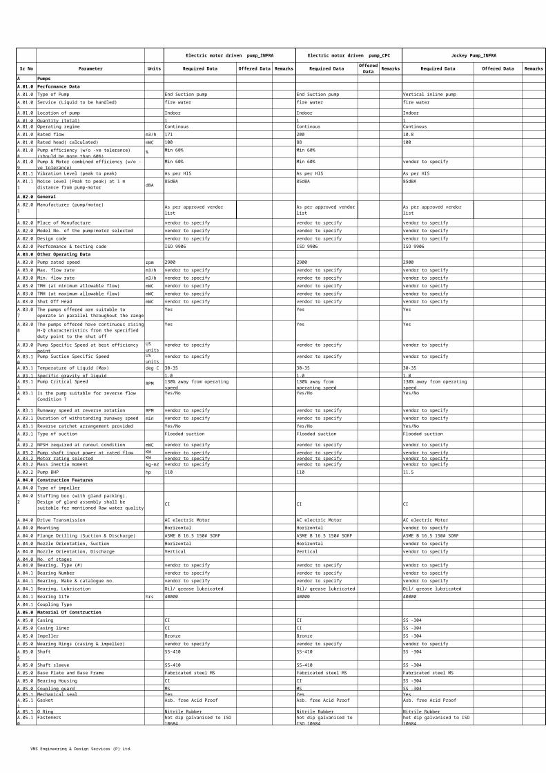
VMS Engineering & Design Services (P) Ltd.
A.06.16 vendor to specify vendor to specify
B.01.00 Diesel Engine B.01.01 Make vendor to specify vendor to specifyB.01.02 Type/designation vendor to specify vendor to specifyB.01.03 Applicable standards vendor to specify vendor to specifyB.01.04 Place of manufacture vendor to specify vendor to specifyB.01.05 Engine gross power vendor to specify vendor to specifyB.01.06 Engine net power (rated continuous output ) vendor to specify vendor to specifyB.01.07 Engine overload capacity (output) for one hour vendor to specify vendor to specifyB.01.08 Engine Starter Motor vendor to specify vendor to specifyB.01.09 vendor to specify vendor to specify
B.01.10 Engine instrument pipe vendor to specify vendor to specifyB.01.11 Silencer with exhaust pipe vendor to specify vendor to specifyB.01.12 Air Filter vendor to specify vendor to specifyB.01.13 Capacity vendor to specify vendor to specifyB.01.14 Day tank vendor to specify vendor to specifyB.01.15 Main oil storage tank be with magnetic oil gauge vendor to specify vendor to specify
B.01.16 Radiator capacity vendor to specify vendor to specifyB.01.17 Type of lubriocation of bearing vendor to specify vendor to specifyB.01.18 Lubrication oil consumption (maximum) vendor to specify vendor to specifyB.01.19 Fuel consumption under N.T.P. vendor to specify vendor to specifyB.01.20 100 % load vendor to specify vendor to specifyB.01.21 75 % load vendor to specify vendor to specifyB.01.22 50 % load vendor to specify vendor to specifyB.01.23 10% overload vendor to specify vendor to specifyB.01.24 Engine speed vendor to specify vendor to specifyB.01.25 Critical speed of shaft vendor to specify vendor to specifyB.01.26 Method of engine cooling vendor to specify vendor to specifyB.01.27 Exhaust outlet diameter vendor to specify vendor to specifyB.01.28 Exhaust flow (Total) vendor to specify vendor to specifyB.01.29 Exhaust Stack Height vendor to specify vendor to specifyB.01.30 Exhaust pipe meter vendor to specify vendor to specifyB.01.31 Insulation with cladding sq.meter vendor to specify vendor to specifyB.01.32 Air aspiration vendor to specify vendor to specifyB.01.33 Number of cylinders vendor to specify vendor to specifyB.01.34 Cylinder bore/ stroke vendor to specify vendor to specifyB.01.35 Efficiency % vendor to specify vendor to specifyB.01.36 Base frame vendor to specify vendor to specifyB.02.00 Starting batteryB.02.01 Rated voltage vendor to specify vendor to specifyB.02.02 Type of Battery vendor to specify vendor to specifyB.02.03 vendor to specify vendor to specifyB.02.04 vendor to specify vendor to specify
B.03.00 Battery chargerB.03.01 Type / designation vendor to specify vendor to specifyB.03.02 Voltage Rating vendor to specify vendor to specifyB.04.00 Diesel engine auxiliariesB.04.01 Power requirements (Approx.) vendor to specify vendor to specifyB.04.02 - Cooling fan motor vendor to specify vendor to specifyB.04.03 - Fuel oil transfer pump (if applicable) vendor to specify vendor to specifyB.04.04 - Total power requirements for complete system vendor to specify vendor to specify
B.04.05 Weight (Approx.) vendor to specify vendor to specifyB.04.06 - Complete diesel engine including base frame vendor to specify vendor to specify
B.04.07 - Engine vendor to specify vendor to specifyB.04.08 vendor to specify vendor to specify
B.04.09 vendor to specify vendor to specify
B.04.10 Control Panels(L x W x H) (Approx.) vendor to specify vendor to specifyB.05.00 Noise level at 1 m distance dB(A) 85 dBA 85 dBA B.06.00 Vibration microns vendor to specify vendor to specifyC.01.00 Local Control CubiclesC.01.01 Type and design vendor to specify vendor to specifyC.01.02 Quantity vendor to specify vendor to specifyC.01.03 Make of Control Panel and components vendor to specify vendor to specifyC.01.04 Degree of protection for enclosure IP 55 IP 55C.01.05 vendor to specify vendor to specify
C.01.06 Overall dimensions, mm vendor to specify vendor to specifyC.01.07 Thickness mm 2 2C.01.08 Details of: vendor to specify vendor to specify
vendor to specify vendor to specifyvendor to specify vendor to specifyvendor to specify vendor to specify
C.01.09 Type of visual annunciation/ indications vendor to specify vendor to specify
Max. permissible overall dimension of pump & diesel engine assembly
mm x mm x mm
Faults leading to automatic diesel engine shutdown
Battery capacity at 25 0C Number of permissible start per hour of diesel engine
Dimension of complete Diesel engine including base frame(LxWxH) (Approx.)Type of coupling between diesel engine and pump
Details of each starter indicating No. of start/stop per hour
- Controls- Annunciation- Indications