Embed Size (px)
Citation preview

TERRESTRIAL LASER SCANNER, TERRESTRIAL SYNTHETIC APERTURE RADAR, AND TOPOGRAPHIC DATA: AN INTEGRATION PROPOSAL. Alejandro Marambio, Barbara Pucci Virtual City Modeling Lab, Politecnical University of Catalonia [email protected] [email protected] Andreas Jungner Institute of Geomatics [email protected] Mª Amparo Núñez, Felipe Buill Department of Geotechnical Engineering and Geo-Sciences (ETCG) [email protected] [email protected] KEY WORDS: Terrestrial Laser Scanner, GB-SAR, GPS, geocoding Abstract:
In this paper three techniques are proposed to be integrated: Terrestrial Synthetic Aperture Radar, Terrestrial Laser Scanner and Traditional Topography.
Terrestrial Synthetic Aperture Radar (SAR) is an evolving instrument that can be been used to detect deformations with high accuracy. The Ground-Based SAR instrument used in this paper has an intrinsic accuracy of sub-millimeter level which makes it suitable for high accuracy deformation detection. It is however fundamental to be able to geo-reference radar deformation data to an accurate surface model of the area of interest. This was accomplished using a terrestrial laser scanner.
The use of a terrestrial laser scanner allowed a full facade overview analysis. A high resolution 3D model has been created by registering and optimizing the scanner’s raw data point clouds, creating and editing a polygonal model and texturizing the result with high resolution photos.
The created digital 3D model, is not only a virtual reproduction, useful in visualization and exploration applications, it has also been used to collect all survey results at different levels of integration into one single environment.
By using the DSM generated from laser scanner a geocoding of GB-SAR data was possible while, at the same time, the digital model was georeferenced in the UTM (ED50) 31N Cartographic Coordinates System by using GPS static observations to establish a reference base from which coordinates of the elements were observed using a non-prism total station.
The paper describes in detail all the data collection process during the survey campaign, the three levels of data elaboration and interpretation, and the algorithm for the assessment of the GB-SAR-RAR geocoding.
1. Introduction
In this paper three different technologies are presented: Terrestrial laser scanner topography and GB-SAR.The first allows obtaining a digital surface model with an accuracy of 1-2 cm from the cloud of pints that are converted in a polygonal model.
A ground-based SAR was used because of its potential deformation detection capabilities.
In order to compare both methods it is necessary that the data obtained are in a same reference system. After the data capture the cloud of points has to be georeferenced, in this case the reference system established is the official in Spain, ETRS89 with a coordinate system UTM 31N (Catalonia zone). So, the observations of bases by GPS allows to have stations in this reference system. From these points the coordinates of details will be measured and used in georeferencing the information obtained by TLS and GB-SAR.

2. The survey campaign
The object study of this methodological application has been the expiatory church of Sagrada Família of the Architect Antoni Gaudi. This choice is due to the emblematic value of the monument for the city of Barcelona and not to study or monitorize the monument. This is a work on a grand scale which was begun on 19 March 1882 from a project by the diocesan architect Francisco de Paula del Villar (1828-1901). At the end of 1883 Gaudí was commissioned to carry on the works, a task which he did not abandon until his death in 1926. Since then different architects have continued the work following his original idea. The project is scheduled to be completed in 2026.The building is in the centre of Barcelona, and over the years it has become one of the most universal signs of identity of the city and the country. It is visited by millions of people every year and many more study its architectural and religious content. Today, 127 years later, the building of the church follows Gaudí's original idea and, just as he himself did, the best techniques are applied to make the building work safer, more comfortable and faster: the old manual tools have been replaced by precise electric machines and the materials have been improved to ensure excellent quality in the building process and the final result.
The temple was designed with three facades each finished with four bell towers, the facade of the Nativity to the east, dedicated to the Passion and the west facade of the Gloria at noon.
Especially the study was focused on the “Nacimiento Façade” because it is the most emblematic one.
Gaudi tried to finish the most part of the Nativity facade, since he wanted that it was a reference for the architects that continued his work. This façade is the only one that presents sculptural decoration of the temple finished in Gaudí’s life.
The sculptural group includes natural forms such as rocks, plants and human figures. Mixing scenes from the Bible with mysterious symbols that can be understood only for a reduced group of Gaudi’s server. In the scene the joy of the birth of Jesus highlights. Among the figures one can admire the baby Jesus, St. Joseph, the Virgin, some shepherds and angels.
In one-day campaign Laser scanner and GB-SAR surveying were realized, while the topographic survey was made later in other one day-campaign.
2.1 GB-SAR and GB-RAR campaign
A Real Aperture Radar (RAR) instrument measures distances and is not able to distinguish between different objects located at the same distance. Objects in the same range bin return a cumulative response. This means RAR data are measurements in range and hence is one dimensional.
The Synthetic Aperture Radar (SAR) setup on the other hand acquires hundreds of RAR acquisitions observing the same scene while moving along a rail perpendicular to the illuminated area. This makes it possible to focus the acquisitions into two dimensional data using Fourier transformations. The comparison is shown in Fig.1.
Figure 1: In RAR geometry it is not possible to distinguish between different objects within the range bin.
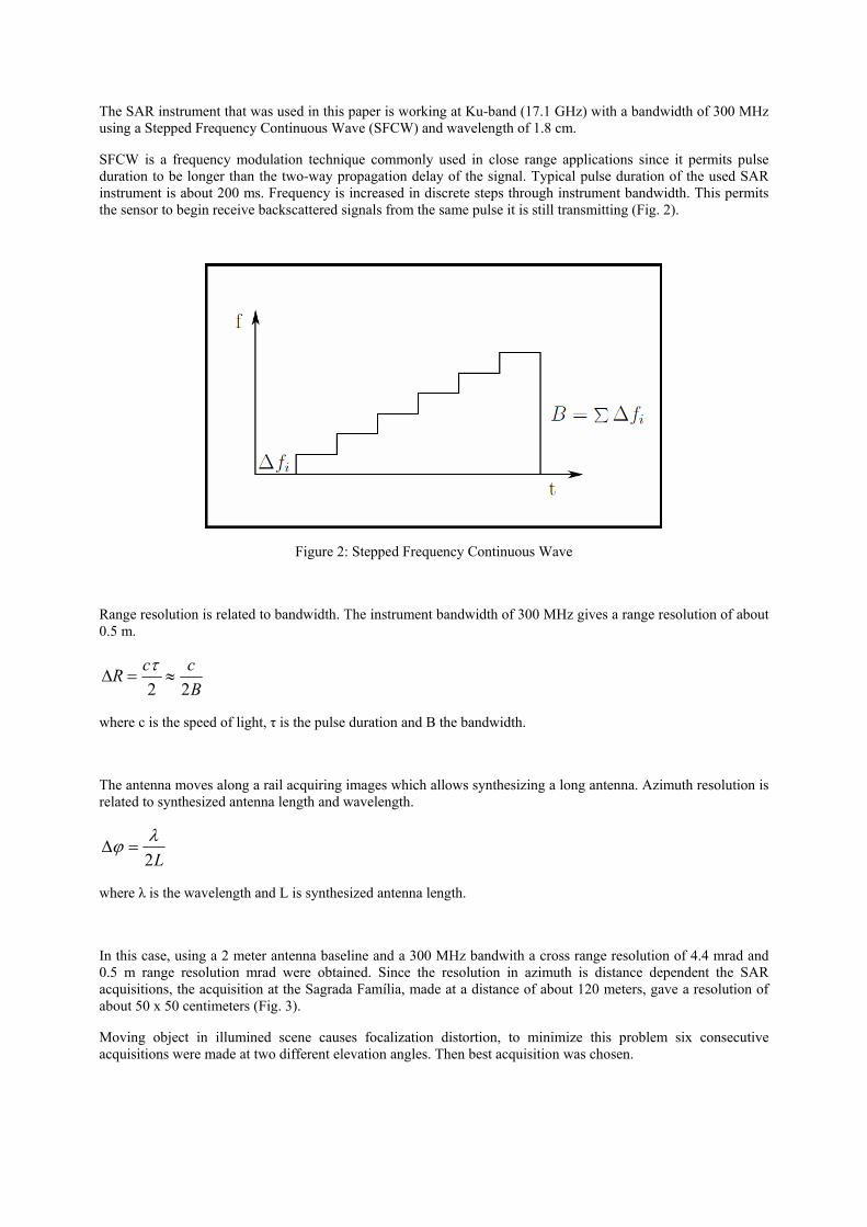
The SAR instrument that was used in this paper is working at Ku-band (17.1 GHz) with a bandwidth of 300 MHz using a Stepped Frequency Continuous Wave (SFCW) and wavelength of 1.8 cm.
SFCW is a frequency modulation technique commonly used in close range applications since it permits pulse duration to be longer than the two-way propagation delay of the signal. Typical pulse duration of the used SAR instrument is about 200 ms. Frequency is increased in discrete steps through instrument bandwidth. This permits the sensor to begin receive backscattered signals from the same pulse it is still transmitting (Fig. 2).
Figure 2: Stepped Frequency Continuous Wave
Range resolution is related to bandwidth. The instrument bandwidth of 300 MHz gives a range resolution of about 0.5 m.
BccR
22≈=∆
τ
where c is the speed of light, τ is the pulse duration and B the bandwidth.
The antenna moves along a rail acquiring images which allows synthesizing a long antenna. Azimuth resolution is related to synthesized antenna length and wavelength.
L2λϕ =∆
where λ is the wavelength and L is synthesized antenna length.
In this case, using a 2 meter antenna baseline and a 300 MHz bandwith a cross range resolution of 4.4 mrad and 0.5 m range resolution mrad were obtained. Since the resolution in azimuth is distance dependent the SAR acquisitions, the acquisition at the Sagrada Família, made at a distance of about 120 meters, gave a resolution of about 50 x 50 centimeters (Fig. 3).
Moving object in illumined scene causes focalization distortion, to minimize this problem six consecutive acquisitions were made at two different elevation angles. Then best acquisition was chosen.
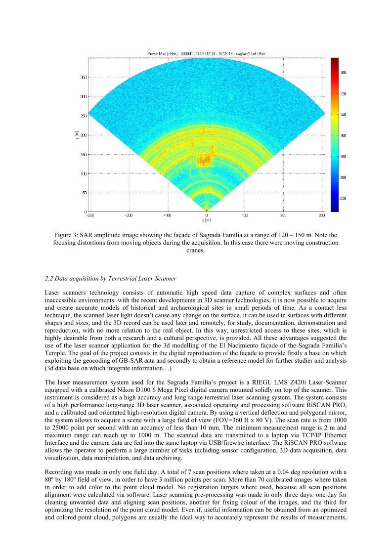
Figure 3: SAR amplitude image showing the façade of Sagrada Família at a range of 120 – 150 m. Note the focusing distortions from moving objects during the acquisition. In this case there were moving construction
cranes.
2.2 Data acquisition by Terrestrial Laser Scanner
Laser scanners technology consists of automatic high speed data capture of complex surfaces and often inaccessible environments: with the recent developments in 3D scanner technologies, it is now possible to acquire and create accurate models of historical and archaeological sites in small periods of time. As a contact less technique, the scanned laser light doesn’t cause any change on the surface, it can be used in surfaces with different shapes and sizes, and the 3D record can be used later and remotely, for study, documentation, demonstration and reproduction, with no more relation to the real object. In this way, unrestricted access to these sites, which is highly desirable from both a research and a cultural perspective, is provided. All these advantages suggested the use of the laser scanner application for the 3d modelling of the El Nacimiento façade of the Sagrada Familia’s Temple. The goal of the project consists in the digital reproduction of the façade to provide firstly a base on which exploiting the geocoding of GB-SAR data and secondly to obtain a reference model for further studier and analysis (3d data base on which integrate information....)
The laser measurement system used for the Sagrada Familia’s project is a RIEGL LMS Z420i Laser-Scanner equipped with a calibrated Nikon D100 6 Mega Pixel digital camera mounted solidly on top of the scanner. This instrument is considered as a high accuracy and long range terrestrial laser scanning system. The system consists of a high performance long-range 3D laser scanner, associated operating and processing software RiSCAN PRO, and a calibrated and orientated high-resolution digital camera. By using a vertical deflection and polygonal mirror, the system allows to acquire a scene with a large field of view (FOV=360 H x 80 V). The scan rate is from 1000 to 25000 point per second with an accuracy of less than 10 mm. The minimum measurement range is 2 m and maximum range can reach up to 1000 m. The scanned data are transmitted to a laptop via TCP/IP Ethernet Interface and the camera data are fed into the same laptop via USB/firewire interface. The RiSCAN PRO software allows the operator to perform a large number of tasks including sensor configuration, 3D data acquisition, data visualization, data manipulation, and data archiving.
Recording was made in only one field day. A total of 7 scan positions where taken at a 0.04 deg resolution with a 80º by 180º field of view, in order to have 3 million points per scan. More than 70 calibrated images where taken in order to add color to the point cloud model. No registration targets where used, because all scan positions alignment were calculated via software. Laser scanning pre-processing was made in only three days: one day for cleaning unwanted data and aligning scan positions, another for fixing colour of the images, and the third for optimizing the resolution of the point cloud model. Even if, useful information can be obtained from an optimized and colored point cloud, polygons are usually the ideal way to accurately represent the results of measurements,

providing an optimal surface description. Moreover, in this specific case study, a digital polygonal model was required, so a three steps process was employed to obtain a final optimized and reduced 3D model useful for GB-SAR 12geocoding3: firstly an automatic triangulation of the optimized point cloud was generated, secondly, in order to reduce this too dense mesh, a reduction on the number of triangles was necessary: from the optimized point cloud a 4 million polygons triangulated model was reached and then reduced to a 1 million polygons model (Fig. 4).
Figure 4: The polygonal model.
Figure 4: A detail of the polygonal model before and after the decimation.

3.3 Topographic survey and laser scanner geocoding
In order to georeference laser scanning data, two stations were established by GPS observations using the static differential method. For the observation the Topcon Hyperpro receivers were used, they were set on tripod with an elevation mask of 15º, with epochs of 15 seconds during 2 hours.
For the baseline computation the fixed points considered was the reference station Las Planas of the Instituto Cartográfico de Cataluña (ICC) and a virtual reference station. The coordinates of both points were obtained with of σx,y=4mm, σz=7mm.
From that points an observation with a laser non-prism total station was made, the coordinates of 7 singular points distributed on El Nacimiento facade were obtained.
The Geocoding of laser scanner data was made by Innovmetric’s PolyWorks: the set of GPS points was identified in the laser scanner model (seven control points) and their coordinates automatically a 3D transformation in the UTM (ED50) Zone 31N Coordinate System (Fig. 5). Five control points were used in the transformation and two more for testing the result.
Figure 5: Georeferentiation of the Polygonal Model
3. Geocoding Procedure
Required data for geocoding is a surface model and known sensor position and rotation between surface model and radar local reference system. Sensor position and rotation is determined identifying known points in acquired images. Corner reflectors that give high radar backscatter are preferably used. Identifying enough points allows over determination using a Least Squares Estimate.
The TLS point was used as surface model. The model was given in Universe Transverse Mercator (UTM) meridian zone 31N with ED50 datum. All points in surface model were projected into radar geometry (line and column) with respect to radar position and rotation between surface model and radar local reference system.
All surface model assigned to the same radar pixel are interpolated to a discrete position. This is the preferred scenario and will be the case if surface model is denser than radar resolution. Multiple surface model points within the same pixel are interpolated using bilinear interpolation or inverse distance weighted (IDW) interpolation in case of insufficient interpolation data.

The result is theoretical radar coverage. Filtering of data to obtain true coverage is done applying a mask visualizing only data that are actually seen by the sensor or areas of interest, e.g. containing deformation. The mask can be based on a high coherence threshold or high gain amplitudes.
Overall it is a very useful tool for GBSAR measurements allowing prediction of measurements a priori given a surface model of the area of interest.
For visualization Google Earth was used. A transformation and datum change was performed from UTM, ED50 to WGS84 for input to Google Earth (Fig.6).
Figure 6: Theoretical coverage of Sagrada Família. Colors represent orthometric height.
4. Final remarks. Conclusions It is possible to predict radar coverage a priori with a surface model. This can also be used to optimize instrument position before the actual GB-SAR acquisition, fact very useful since the instrument is very heavy.
GB-SAR provides an image that it is very difficult to interpret so it is necessary the geocoding of this image to relate it with the studied object, for this task is essential to have a digital surface model, in this case obtained by terrestrial laser scanning. Being also necessary to know the coordinates of some identifiable details in the cloud of points (at least 5) to georeference all the data.
References
[1] Bernardini G., Pasquale G. De, Bicci A., Marra M., Coppi F., Ricci P. 2007. Microwave interferometer for ambient vibration measurement on civil engineering structures: 1. Principles of the radar technique and laboratory tests. Proc. EVACES'07. [2] Bernardini G., Pasquale G. De. 2007. Microwave interferometer for ambient vibration measurements on civil engineering structures: 2. Application to full-scale Bridges. Proc. EVACES'07.