Embed Size (px)
Citation preview

Terahertz Image Enhancing Based on the PhysicalModel and Multiscale Retinex Algorithmqi mao
Dongbei University of Finance and Economicsyunlong zhu ( [email protected] )
Fudan Universityjingbo liu
Dongguan University of Technologycixing lv
Dongguan University of Technologyyao lu
Dongguan University of Technologydongshan wei
Dongguan University of Technologyshihan yan
Chongqing Institute of Green and Intelligent Technology
Research Article
Keywords: physical model, multiscale retinex, THz images
Posted Date: April 9th, 2021
DOI: https://doi.org/10.21203/rs.3.rs-393245/v1
License: This work is licensed under a Creative Commons Attribution 4.0 International License. Read Full License

Terahertz image enhancing based on the
physical model and multiscale retinex algorithm
Qi Mao 1, Jingbo Liu 2+, Yunlong Zhu 3*, Cixing Lv 2, Yao Lu 2, Dongshan Wei 2, and Shihan Yan 4
1School of Management Science and Engineering, Dongbei University of Finance and Economics, Dalian
116025, China 2 School of Electrical Engineering and Intelligentization, Dongguan University of Technology, Dongguan
523808, China 3Academy for Engineering & Technology, Fudan University, Shanghai 200433, China 4Chongqing Engineering Research Center of High Resolution and Three-Dimensional Dynamic Imaging
Technology, Chongqing Institute of Green and Intelligent Technology, Chongqing 400714, China
*Corresponding authors:([email protected]) +these authors contributed equally to this work
Abstract To settle the THz image degradation problem, we propose an effective enhancement method based on
the physical model and multiscale retinex (MSR) algorithm. The overall enhancing process involves two
parts: reconstruction and enhancement. Firstly, the original THz images are reconstructed by a
mathematical model, which is built and considered the THz absorption variate and Gaussian distribution
of the beam. Then, the original images are processed by the proposed algorithm, which is combined the
atmospheric scattering model and optimized MSR algorithm. The proposed algorithm not only recover
the image scene radiance and remove haze, but also can make a compromise of the dynamic range of
grayscale and edge enhancement of image. Results on a variety of THz images demonstrate our method
can effectively improve the quality of THz images and retain sufficient image details.
Introduction Terahertz imaging technology has been widely researched in the field of biomedical science, security
control, and non-destructive detection [1]. Non-destructive detection of industrial products has great
significance for improving production efficiency [2]. The optical inspection technology cannot observe the
inside of the integrated circuit because the material of packaging cannot be penetrated. Ultrasonic testing
is time-consuming and laborious, and the ultrasonic couplant used in the testing process can contaminate
the products [3]. Although X-ray technology is widely used in the industrial field, its ionization
characteristics can cause damage to the internal circuit structure [4]. However, the THz image degradation
is still seriously affected by the fluctuation effects from the source, the intrinsic noise from the detector,
and the limit of the THz system. The effective THz imaging technology has significant value in the applicant
of non-destructive detection.

In recent years, the image enhancing techniques based on image enhancement and physical models have
a significant development. In the enhancing approaches based on physical models, there are several
methods. Schildknecht et al. used the bind deconvolution and a point-spread function develop the
biomedical image of a histopathological sample [5]. In order to distinguish counterfeit integrated circuit,
Kiarash built a THz mathematical modeling for the point spread function [6]. Olivieri et al. improved the
resolution of single-pixel imaging by combining nonlinear THz generation with time-resolved field
measurements [7]. Kaiming He et al. used a dark channel prior removed the haze and recover a high
quality image from a single input image [8]. These approaches produce impressive results. However, it
cannot obtain high quality images and recover sufficient image details.
To enhance the THz image contrast and weaken these effects, many enhancing algorithms had been
proposed in THz image processing. Trofimov et al. used high contrast correlation function to improve the
image quality of the passive THz imaging devices [9]. Chen et al. proposed the combined approach of the
discrete wavelet transform and retinex algorithm to enhance continuous wave terahertz (CW-THz)
scanning images contrast and denoising [10]. Wong et al. enhanced the THz image resolution beyond the
diffraction limit, which through reconstructing the signal using sinc-envelope and feeding it into the
process of a 2D blind deconvolution procedure [11]. Burford et al. applied the high-pass error function
filters to obtain the balance of image clarity and signal distortion [12]. Zhang et al. proposed a THz
amplitude polynomial principle component regression algorithm for the inspection of aramid-basalt
hybrid composite laminates [13]. Muniyappan et al. enhanced images by using contrast limited adaptive
histogram equalization method [14]. Zhang et al. distinguished different biological tissues through
adopting a composite multiscale entropy approach of THz signal complexity analysis [15]. The single-scale
retinex (SSR) algorithm based on a homomorphic filtering way was proposed by Jobson et al [16]. Rahman
et al. proposed the multiscale retinex (MSR) algorithm by linearly weighting multiple fixed-scale color
channels [17]. Although the methods have made the great improvements in the field of the THz image
resolution, the enhanced images may amplifier noise details or generate distortion. It are still not
sufficient for industrial detection.
Based on the above discussion, the physical model and image enhancement for image processing have
their disadvantages. We propose an effective enhancement method based on the physical model and
MSR algorithm. The overall enhancing process involves two parts: reconstruction and enhancement.
Firstly, the original THz images are reconstructed by a mathematical model, which is built and considered
the THz absorption variate and Gaussian distribution of the beam. The original images are still hazy.
Secondly, the original images are processed by the enhancing algorithm, which is based on the
atmospheric scattering model and optimized MSR algorithm. The atmospheric scattering model can
recover the image scene radiance and remove haze. The optimized MSR algorithm balances the dynamic
range of the grayscale and edge enhancement of the images. Results on a variety of THz images
demonstrate our method can effectively improve the quality of THz images and retain sufficient image
details.
The rest of this paper is organized as follows. In Section 2, the atmospheric scattering model and MSR
algorithm are briefly reviewed. Section 3 shows details of the mathematical model and proposed
algorithm. Section 4 presents the experimental and results, which include a comparison of quantitative
analysis. Finial, Section 5 gives the conclusions of this work.

Theoretical background
A: Atmospheric scattering model
In computer vision, it is widely used to describe the formation of blurred images using an optical
attenuation model [18]. It is expressed as follows: I(𝑥) = t(𝑥)J(𝑥) + (1 − 𝑡(𝑥))A (1)
where I(𝑥) is the observed image, 𝑡(𝑥) is the scene transmission map, J(𝑥) is the scene radiance, and
A is the global atmospheric light value. 𝑡(𝑥) describes the portion of light which is not scattered. The
goal is to recover J(𝑥) , 𝑡(𝑥) , and A from I(𝑥) . The first term on the right-hand side is the direct
attenuation and related to the media transmission coefficient. The second term is the airlight. The direct
attenuation expresses the scene radiance and its decay in the medium, and the airlight describes scattered
light leads to the shift of the scene colors. The degradation of image quality is exacerbated by the
brightness of the scene being exhausted by fog and distant objects.
B: MSR algorithm
To better explain the advantages of the proposed method based on the MSR, we briefly present the details
of MSR algorithm. According to retinex theory, the brightness perceived by the human eye depends on
the illumination of the environment and the reflection of light from the surface of the object. The
mathematical expression is I(x, y) = L(x, y) ∙ 𝑅(x, y) (2)
where I(x, y) is the observed image, L(x, y) is its illuminance function which depends on the source of
illumination and resolve the dynamic range of the image, and R(x, y) is its reflectance function which
depend on the target object that carries image detail and is independent of lighting. The R(x, y) represents
the reflection component of a target object carrying image detail information. It corresponds to high
frequency component, such as the texture information and structure of the image. The L(x, y) is
estimated by low-filtering the I(x, y) using 𝐺𝑛(𝑥, 𝑦). The goal of retinex algorithm is to obtain the
reflection image 𝑅(x, y) by removing L(x, y) from observed image I(x, y).
The SSR could not simultaneously deal with dynamic range or tonal contrast, and may even cause halo
phenomenon. For compensating the deficiency of the SSR algorithm, the MSR algorithm adopts the sum
of different weighted scales of SSR. The MSR algorithm is a balance between image color fidelity and
dynamic range, which is expressed as follows. R𝑀𝑆𝑅𝑖(x, y) = ∑ 𝜔𝑛 ∙ (ln 𝐼𝑖 (𝑥, 𝑦) − ln 𝐺𝑛 (𝑥, 𝑦) ∗ ln 𝐼𝑖 (𝑥, 𝑦))𝑁𝑛=1 (3)
𝐺𝑛(𝑥, 𝑦) = 12𝜋𝜎𝑛2 𝑒−𝑥2+𝑦22𝜎𝑛2 (4)
where R𝑀𝑆𝑅𝑖 is the output of the 𝑖th component image I(x, y) converted using MSR algorithm, and
G(𝑥, 𝑦) is the Gaussian function of N different scales. Generally, N is the number of scales and set to 3 in
actual applications. Typically, σ < 50 is the small scale, 50 ≤σ<100 is the medium scale, σ ≥ 100 is
the large scale, and ∬ Gn(x, y)𝑑𝑥𝑑𝑦 = 1. The ∑ 𝜔𝑛 = 1𝑁𝑛=1 and each value of 𝜔𝑛 is equal.
Proposed methods
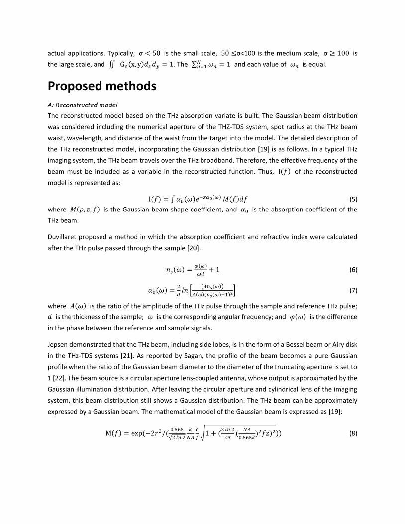
A: Reconstructed model
The reconstructed model based on the THz absorption variate is built. The Gaussian beam distribution
was considered including the numerical aperture of the THZ-TDS system, spot radius at the THz beam
waist, wavelength, and distance of the waist from the target into the model. The detailed description of
the THz reconstructed model, incorporating the Gaussian distribution [19] is as follows. In a typical THz
imaging system, the THz beam travels over the THz broadband. Therefore, the effective frequency of the
beam must be included as a variable in the reconstructed function. Thus, I(𝑓) of the reconstructed
model is represented as:
I(𝑓) = ∫ 𝛼0(𝜔)𝑒−𝑧𝛼0(𝜔) 𝑀(𝑓)𝑑𝑓 (5) where 𝑀(𝜌, 𝑧, 𝑓) is the Gaussian beam shape coefficient, and 𝛼0 is the absorption coefficient of the
THz beam.
Duvillaret proposed a method in which the absorption coefficient and refractive index were calculated
after the THz pulse passed through the sample [20].
𝑛𝑠(𝜔) = 𝜑(𝜔)𝜔𝑑 + 1 (6)
𝛼0(𝜔) = 2𝑑 𝑙𝑛 [ (4𝑛𝑠(𝜔))𝐴(𝜔)(𝑛𝑠(𝜔)+1)2] (7)
where 𝐴(𝜔) is the ratio of the amplitude of the THz pulse through the sample and reference THz pulse; 𝑑 is the thickness of the sample; 𝜔 is the corresponding angular frequency; and 𝜑(𝜔) is the difference
in the phase between the reference and sample signals.
Jepsen demonstrated that the THz beam, including side lobes, is in the form of a Bessel beam or Airy disk
in the THz-TDS systems [21]. As reported by Sagan, the profile of the beam becomes a pure Gaussian
profile when the ratio of the Gaussian beam diameter to the diameter of the truncating aperture is set to
1 [22]. The beam source is a circular aperture lens-coupled antenna, whose output is approximated by the
Gaussian illumination distribution. After leaving the circular aperture and cylindrical lens of the imaging
system, this beam distribution still shows a Gaussian distribution. The THz beam can be approximately
expressed by a Gaussian beam. The mathematical model of the Gaussian beam is expressed as [19]:
M(𝑓) = exp (−2𝑟2/( 0.565√2 𝑙𝑛 2 𝑘𝑁𝐴 𝑐𝑓 √1 + (2 𝑙𝑛 2𝑐𝜋 ( 𝑁𝐴0.565𝑘)2𝑓𝑧)2)) (8)

where 𝑘 is factor determined by the truncation ratio and irradiance; NA is the numerical aperture of the
THZ-TDS system; 𝑓 is the frequency of the THz beam; z is the distance between the object and waist on
the z axis; and 𝑐 is the speed of light.
Finally, substituting Eq. (8) into Eq. (5) gives the THz image reconstructed function (Eq. (9)) as:
I(𝑓) = ∫(exp (−2𝑟2/( 0.565√2 𝑙𝑛 2 𝑘𝑁𝐴 𝑐𝑓 √1 + (2 𝑙𝑛 2𝑐𝜋 ( 𝑁𝐴0.565𝑘)2𝑓𝑧)2))α0𝑒−𝑧𝛼0) 𝑑𝑓 (9)
B: Proposed algorithm
The original THz images obtained from the reconstructed model are hazy and further enhanced. The
proposed algorithm based on the atmospheric scattering model and MSR algorithm is used to enhance
the THz images. The proposed algorithm not only recovers the image scene radiance and removes haze,
but also can make a compromise of the dynamic range of grayscale and edge enhancement of the image.
The algorithm scheme is described in detail.
Step 1: Data input I(𝐱, 𝐲)
The data input I(x, y) is obtained from the original THz image, which is reconstructed from the (9).
Step 2: Optimized transmission 𝒕(𝒙) 𝐼dark is the minimum value of three channels in each pixel. According to (9), the color of the air in a
hazy image is usually very similar to the atmospheric light A. µ is set to 0.3. A = max(max (𝐼dark(x, y))) (10) 𝑡(𝑥) = 1 − µ ∙ (𝐼dark(x, y)/A) (11)
Step 3: Recover the image scene radiance 𝑰′(𝐱, 𝐲)
In order to recover the image scene radiance, the (1) is rewrote as (11). The 𝑡0 is set to 0.1.
𝐼′(x, y) = 𝐼(x,y)−𝐴max (𝑡(𝑥),𝑡0) + 𝐴 (12)
Step 4: Optimized MSR
According the (4) and ∬ Gn(x, y)𝑑𝑥𝑑𝑦 = 1 , calculate the Gn(x, y) (n=3) for each scale: σ1 =40 , σ2 = 80 , and σ3 = 150 . The Gn(x, y) is regarded as a low-pass filter. Put the I (x, y) and Gn(x, y) into (13), compute the R𝑀𝑆𝑅(x, y). The α and β are respectively added and regarded as
the gain factor and adjustment coefficient in optimized MSR. In this work, the weighting coefficients 𝜔𝑛
are 0.333, 0.333, and 0.334.
𝑅(x, y) = β ∙ ln (𝛼3 + 1) ∙ ∑ 𝜔𝑛 ∙ (ln 𝐼 ′(𝑥, 𝑦) − ln 𝐺𝑛 (𝑥, 𝑦) ∗ ln 𝐼 ′(𝑥, 𝑦))𝑁𝑛=1 (13)

Where the α is 16 ∙ √𝑀 < α < 14 ∙ √𝑀 and β is 0.8. M is the number of pixels of observed image.
Step 5: Data output 𝑹′(𝐱, 𝐲) 𝑅′(x, y) = 𝑒𝑹(𝐱,𝐲) (14)
Obtain the enhanced image from the 𝑅′(x, y).
Results The experiment is implemented on the T-Gauge 5000 manufactured by Advanced Photonics. The focal
length of the TDS system is 75 mm and the diameter of the lens is 38 mm. The point-by-point raster
scanning is adopted in this work. The scanning step size and speed of the mobile station were 0.25 mm
and 50 mm s-1, respectively. The signal noise ratio of THz wave above 1 THz is small, and the available
frequency is range from 0.3 to 0.8 THz. The original THz images are performed by the different
approaches, including the contrast-limited adaptive histogram equalization (CLAHE), grey level
transformation (GLT), multiscale retinex (MSR), and our method. Our specimens were STC89C52RC IC,
PCB board, copper-coated iron bookmarks of flower and butterfly.
Quantitative evaluation of image enhancement methods is discussed in the following. Several indicators
are used to quantitatively evaluate the performance of the different image enhancement methods. For
example, the standard deviation (SD) is mainly used to measure the overall contrast of the image. The
entropy (EN) is mainly used to measure the expected value of a random variable in an image. In other
words, EN reflects the degree of chaos in grey-scale map. The spatial frequency (SF) is an indicator of the
intensity of gray mutation in an image. For the image, the edge part of the image is the abrupt part. The
more rapid the mutation, the sharper the edge. The peak signal-to-noise ratio (PSNR) describes the mean
square error (MSE) relationship between the original image and the enhanced image using the
enhancement method. The MSE represents the expected error between the original image and enhanced
image.
A: IC imaging
In Figure. 1, we show the enhanced results of THz IC images. The original image is relatively blurry with
low image contrast. The high image contrast of the enhanced image is achieved from the proposed
algorithm. The proposed algorithm obtains a better quality with high image contrast, clear IC pins, and a
rational white balance in the grayscale images. In Figure. 1 (b) and (d), the image using the CLAHE and
MSR methods are close and slightly worse in the sight of visual sense. The Figure. 1(c) shows good image
contrast and therefore the overall enhanced image looks darker. As shown in Table 1, the EN of the image
using the GLT method is larger than other methods and therefore the PSNR is large. Correspondingly, the
PSNR represented is low. Comparing the original THz image and enhanced images, the image in Figure. 1
(b), (c), and (d) is overall slightly bad white balance and low contrast.

The IC X-ray image is shown in Figure. 2 (a). The Figure. 2 (b) shows the enhanced IC image using the
proposed algorithm. According to the results, the sizes of the outside pins are highly consistent with those
obtained from the X-ray image. For example, the values of rulers X1 and T1 are 49.68 mm and 50.18 mm,
respectively, with a 1% margin of error. The values of rulers X2 and T2 are 3.92 mm and 4.35 mm,
respectively, with an error margin of 10%. The values of rulers X3 and T3 are 3.3 mm and 3.48 mm,
respectively, with an error margin of 5%. The values of rulers X4 and T4 are 13.66 mm and 14.9 mm,
respectively, with an error margin of 8%. Given these results, it can be concluded that the proposed
algorithm is better.
Figure. 1. (a) Original IC THz image; (b), (c), (d), (e) was the enhancement IC images using the CLAHE, GLT, MSR, and
proposed algorithm, respectively.
Table 1. Objective assessments of the CLAHE, GLT, MSR, and proposed algorithm.
Image
Metric Original CLAHE GLT MSR proposed algorithm
IC
SD 38.12 46.99 54.33 46.18 53.06
EN 6.54 7.35 7.39 7.35 7.53
SF 27.04 32.72 31.71 32.29 35.5
MSE — 0.89×10³ 1.24×10³ 1.19×10³ 0.81×10³
PSNR — 18.59 17.17 17.62 19.02
B: PCB board imaging
The enhanced THz images of the PCB board are shown in Figure. 2. The size is 8.5cm × 9.5cm, which is
fabricated according to USAF1951. The original image is slightly blurry with low image contrast. However,
the finer lines look blur together. The high image contrast and signal to noise ratio are achieved from the
proposed algorithm. It can obtain the grayscale image, which is equipped with high image contrast, clear
boundaries of the finer lines, and a rational white balance. In Figure. 2 (b) and (d), the image contrasts
using the CLAHE and MSR methods are also close and comparatively worse in the sight of visual sense.
The Figure. 2 (c) is better at good image contrast and lower noise. However, the overall image is

excessively saturated and the finest lines are almost disappeared. The brightness and saturation of the
Figure. 2 (e) are controlled well. As shown in Table 2, the EN of the image using the GLT method is larger
than images using the CLAHE and MSR methods. The SF of the image enhanced by MSR is the highest and
therefore shows a lot of noise and distortion. Correspondingly, its PSNR represented is lowest. Comparing
the original THz image and enhanced images, the proposed algorithm shows a very well ability of balance
of the image contrast, white balance, and signal to noise ratio.
Figure. 2. (a) Original THz image; (b), (c), (d), (e) was the enhancement PCB images using the CLAHE, GLT, MSR, and
proposed algorithm, respectively.
Table 2. Objective assessments of the CLAHE, GLT, MSR, and proposed algorithm.
Image Metric Original CLAHE GLT MSR proposed algorithm
PCB board
SD 51.17 55.76 61.61 55.79 62.53
EN 5.6 6.34 1.09 7.3 1.67
SF 22.64 20.26 26.53 43.47 29.91
MSE — 0.61×10³ 0.37×10³ 1.56×10³ 0.18×10³
PSNR — 20.2 22.44 16.19 25.22
C: Flower bookmark imaging
The enhanced results of the THz flower bookmark images are shown in Figure. 3. The size is 7.2 cm × 5 cm
× 0.05 cm, including the stamen and texture of the petal. The original image is seriously blurry with low
image contrast. The high image contrast and signal to noise ratio are achieved from our method. It can
obtain a grayscale image, which is equipped with high image contrast, clear edges of the stamen and
texture of the petal, and a rational white balance. In Figure. 3 (b) and (d), the image contrast obtained
from the CLAHE and MSR methods are also close and slightly worse in the sight of visual sense. Although
the Figure. 3 (c) shows good image contrast and lower noise. Due to the overall image is excessively
saturated, the stamen and texture of the petal are almost invisible. The brightness and saturation of the
Figure. 3 (e) are controlled well. As shown in Table 3, the EN of the image obtained from the GLT method
is larger than it achieved from the CLAHE and MSR methods. The SF of the image enhanced by the MSR
method is the highest. Therefore, it shows a lot of noise and distortion, which seriously affects the value

of PSNR. Comparing the original THz image and enhanced images, it can be concluded that our method
works well.
Figure. 3. (a) Original THz image; (b), (c), (d), (e) was the enhancement THz images using the CLAHE, GLT, MSR, and
proposed algorithm, respectively.
Table 3. Objective assessments of the CLAHE, GLT, MSR, and proposed algorithm.
Image Metric Original CLAHE GLT MSR proposed algorithm
Flower
SD 39.83 50.97 67.97 49.27 64.96
EN 6.59 7.17 2.6 7.17 6.8
SF 18.53 36.56 31.48 36.56 32.54
MSE — 0.58×10³ 1.7×10³ 0.57×10³ 0.56×10³
PSNR — 20.45 15.78 20.53 20.61
D: Butterfly bookmark imaging
The enhanced THz images of the butterfly bookmark are shown in Figure. 4. The size is 6 cm × 6.5 cm ×
0.05 cm, including the stamen and texture of the petal. The original image is seriously blurry with low
image contrast and saturation. The Figure. 4 (c) shows low image contrast and saturation. In Figure. 4 (b),
(c), and (d), the image contrast obtained from the CLAHE, MSR, and proposed algorithm are almost close
in the sight of visual sense. As shown in Table 4, the EN of the image obtained from our proposed method
is larger than others. The SF of the image obtained from the proposed algorithm is slightly smaller than it
from the MSR method. But, the PSNR of the image obtained from the proposed algorithm is the best.
From above discussion, the proposed algorithm shows very well able to balance the image contrast, white
balance, and signal to noise ratio.
Figure 4. (a) Original image; (b), (c), (d), (e) was the enhancement images using the CLAHE, GLT, MSR, and
proposed algorithm, respectively.

Table 4. Objective assessments of the CLAHE, GLT, MSR, and proposed algorithm.
Image Metric Original CLAHE GLT MSR proposed algorithm
Butterfly
SD 36.58 54.87 67.41 62.56 72.26
EN 5.98 7.26 2.95 7.19 7
SF 15.88 29.38 33.58 34.28 33.44
MSE — 1.76 1.86 2.07 0.66
PSNR — 17.91 15.42 14.96 19.91
Discussion
This paper presents an effective enhancement method based on the physical model and MSR algorithm.
The overall enhancing process involves two parts: reconstruction and enhancement. Firstly, the original
THz images are reconstructed by a mathematical model, which is built and considered the THz absorption
variate and Gaussian distribution of the beam. The original THz images obtained from the reconstructed
model are hazy and further enhanced. Then, the original images are processed by the proposed algorithm,
which is combined the atmospheric scattering model and optimized MSR algorithm. The atmospheric
scattering model can recover the image scene radiance and remove haze. The optimized MSR algorithm
balances the dynamic range of the grayscale and edge enhancement of the images. Besides a subjective
evaluation, the performance of the different image enhancement methods is quantitatively evaluated
using several indicators, SD, EN, SF, MSE, and PSNR. The experimental results clearly show our enhancing
algorithm can effectively improve the quality of THz images. Furthermore, this method can be applied to
other fields as well, including solid-state, chemical and biological systems, and body security screening.
References: [1] Stantchev RI, Sun B, Hornett SM, Hobson PA, Gibson GM, Padgett MJ, et al. Noninvasive, near-field
terahertz imaging of hidden objects using a single-pixel detector. Sci Adv, e1600190, (2016).
doi:10.1126/sciadv.1600190. [2] Sung-Hyeon, Park, Jin-Wook, Jang, Hak-Sung, Kim. Non-destructive evaluation of the hidden voids in
integrated circuit packages using terahertz time-domain spectroscopy. J Micromech Microeng, 95007,
(2015) [3] Martin E, Larato C, Clément A, Saint-Paul M. Detection of delaminations in sub-wavelength thick
multi-layered packages from the local temporal coherence of ultrasonic signals. Ndt&E Int, 280-91,
(2008). doi:10.1016/j.ndteint.2007.10.013. [4] Hertz HM, Krdel M, Dehlinger A, Seim C, Stiel H. Laboratory water-window x-ray microscopy. Optica,
(2020) [5] Schildknecht C, Kleine-Ostmann T, Knobloch P, Rehberg E, Koch M. Numerical image enhancement
for THz time-domain spectroscopy., (2002)

[6] Ahi K. Mathematical Modeling of THz Point Spread Function and Simulation of THz Imaging Systems.
Ieee T Thz Sci Techn, 747-54, (2017). doi:10.1109/TTHZ.2017.2750690. [7] Olivieri L, Totero Gongora JS, Pasquazi A, Peccianti M. Time-Resolved Nonlinear Ghost Imaging. Acs
Photonics, 3379-88, (2018). doi:10.1021/acsphotonics.8b00653. [8] He K, Sun J, Tang X. Single Image Haze Removal Using Dark Channel Prior. IEEE Trans Pattern Anal
Mach Intell, 2341-53, (2011). doi:10.1109/TPAMI.2010.168. [9] Schildknecht C, Kleine-Ostmann T, Knobloch P, Rehberg E, Koch M. Numerical image enhancement
for THz time-domain spectroscopy., (2002) [10] Chen L, Zhang M, Hu Q, Huang Y, Liang H, Shen C, et al. CW-THz image contrast enhancement using
wavelet transform and Retinex., 9675, 96751M, (2015). doi:10.1117/12.2199505. [11] Wong TM, Kahl M, Haring Bolívar P, Kolb A. Computational Image Enhancement for Frequency
Modulated Continuous Wave (FMCW) THz Image. Journal of Infrared, Millimeter, and Terahertz
Waves, 775-800, (2019). doi:10.1007/s10762-019-00609-w. [12] Burford NM, El-Shenawee MO. Enhancement of terahertz imaging of packaged power electronic
devices., 1300-01, (2015). doi:10.1109/APS.2015.7305039. [13] Zhang H, Sfarra S, Osman A, Szielasko K, Stumm C, Sarasini F, et al. Terahertz Amplitude Polynomial
Principle Component Regression for Aramid–Basalt Hybrid Composite Laminate Inspection. Ieee T Ind
Inform, 5601-09, (2018). doi:10.1109/TII.2018.2870670. [14] Muniyappan S, Allirani A, Saraswathi S. A novel approach for image enhancement by using contrast
limited adaptive histogram equalization method., 1-06, (2013). doi:10.1109/ICCCNT.2013.6726470. [15] Zhang R, He Y, Liu K, Zhang L, Zhang S, Pickwell-MacPherson E, et al. Composite multiscale entropy
analysis of reflective terahertz signals for biological tissues. Opt Express, 23669, (2017).
doi:10.1364/OE.25.023669. [16] Jobson, Daniel, J., Rahman, Zia-ur. Properties and performance of a center/surround retinex. Ieee T
Image Process, (1997) [17] Rahman ZU, Jobson DJ, Woodell GW. Multiscale retinex for color rendition and dynamic range
compression. Proc Spie, 183-91, (1996) [18] Narasimhan SG, Nayar SK. Vision and the Atmosphere. Int J Comput Vision, 233-54, (2002) [19] Ahi K, Shahbazmohamadi S, Asadizanjani N. Quality control and authentication of packaged
integrated circuits using enhanced-spatial-resolution terahertz time-domain spectroscopy and
imaging. Opt Laser Eng, 274-84, (2018). doi:10.1016/j.optlaseng.2017.07.007. [20] Duvillaret L, Garet F, Coutaz JL. Highly precise determination of optical constants and sample
thickness in terahertz time-domain spectroscopy. Appl Optics, 409, (1999) [21]Jepsen PU, Keiding SR. Radiation patterns from lens-coupled terahertz antennas. Opt Lett, 807, (1995) [22] Sagan S. Handbook of Optical and Laser Scanning, Boca Raton, USA: CRC Press; 2011.

Acknowledgements This work was financed by the National key research and development program of China (No.
2018YFB1702701 and No. 2018YFB1004004) and China Postdoctoral Science Foundation (No.
2018M643651).
Author contributions Q. M carried out the laboratory work, data analysis, methodology, software, validation, data curation, and paper writing. J. L participated in conceptualization, administration, Funding acquisition. Y. Z designed the visualization. C. L and Y. L participated in supervision and project administration. D. W and S. Y carried out the investigation and resources.
Competing interests The authors declare no competing interests.

Figures
Figure 1
(a) Original IC THz image; (b), (c), (d), (e) was the enhancement IC images using the CLAHE, GLT, MSR,and proposed algorithm, respectively.
Figure 2
(a) Original THz image; (b), (c), (d), (e) was the enhancement PCB images using the CLAHE, GLT, MSR,and proposed algorithm, respectively.

Figure 3
(a) Original THz image; (b), (c), (d), (e) was the enhancement THz images using the CLAHE, GLT, MSR,and proposed algorithm, respectively.
Figure 4
(a) Original image; (b), (c), (d), (e) was the enhancement images using the CLAHE, GLT, MSR, andproposed algorithm, respectively.