Embed Size (px)
Citation preview
1
TEMPERATURE CALCULATIONS IN SPENT NUCLEAR FUEL CASK USING COBRA-SFS
MARTA GALBÁN, MIRIAM LLORET
ENUSA Industrias Avanzadas S.A., S.M.E, Spent Nuclear Fuel
Santiago Rusiñol, 28040 Madrid – Spain
JULIO BENAVIDES, GONZALO JIMÉNEZ Universidad Politécnica de Madrid, Escuela Técnica Superior de Ingenieros Industriales
José Gutiérrez Abascal, 28006 Madrid - Spain
ABSTRACT
Currently, spent nuclear fuel temperature calculations are focused on
maximum temperatures in compliance with the limits specified in the Interim
Staff Guidance of the NRC ISG-11 rev.3 for cladding, 400ºC for normal
conditions of storage and short-term loading operations, to prevent
unacceptable clad degradation during storage. These calculations can be
extremely conservative in some cases, and non-realistic in others, especially
when material ductility is an important factor.
Therefore, the need to develop new capabilities arises in ENUSA in order to
obtain more realistic results of spent fuel temperature distribution during
transport and storage. As a result, a long-term collaboration project between
ENUSA and Universidad Politécnica de Madrid (UPM) has been launched.
In the first phase of the project, COBRA-SFS, a computer code developed by
Pacific Northwest Laboratory is being used. This is a thermal-hydraulic
analysis code specific for spent fuel storage and transportation casks. The
TN-24P storage cask configured for PWR spent fuel with helium backfill gas
has been chosen. Creating different simulation cask models and developing
a methodology to obtain useful understanding of thermal behaviour of spent
fuel storage and transportation systems is one of the main objectives of this
project. Additionally, several scripts that process COBRA-SFS input and
output data have been developed.
1. Introduction
This collaboration project between ENUSA Industrias Avanzadas S.A., S.M.E, and
Universidad Politécnica de Madrid, is focused on developing realistic thermal
calculations of spent fuel during dry storage and transportation. Therefore, two codes
are being used: COBRA-SFS and the CFD code STAR-CCM+.
In this paper, COBRA-SFS code is described and the results are shown for the TN-24P
cask.
2. COBRA-SFS code
The COBRA-SFS (Spent Fuel Storage) code provides the capability for thermal
modelling of the entire storage module (including fuel assemblies, canister internals and
overpack). This code performs thermal-hydraulic analyses of multi-assembly spent fuel
storage and transportation systems. It uses a finite difference approach to predict flow
and temperature distributions in spent fuel storage systems and fuel assemblies, under
forced and natural convection heat transfer conditions, in both steady-state and
transients.

2
2.1 Basic Structure of COBRA-SFS Modeling
To be capable of analysing fuel temperature evolution in a cask container, the COBRA-
SFS code needs an input where the container is described by parts.
The input is highly structured, it is organized into five basic categories or groups:
1. The physical properties of the solid materials and working fluid
2. The flow channel geometry and solid node structure
3. The constitutive models for the flow and heat transfer solutions
4. The boundary conditions
5. Solution control parameters and output options
A COBRA-SFS cask model is constructed by dividing the cask into a set of finite volumes
or nodes, consisting of assemblies which are made up of channels to represent the fluid
flow paths and rods to represent the fuel. The channels are bounded by solid conduction
nodes (slabs) that represent the solid material of the cask, such as assembly canisters,
support baskets, shielding layers, and inner and outer structural shells.
Figure 1 is a schedule of the TN-24P storage cask container simulated in this project
with 24 PWR spent fuel assemblies each with a 15x15 rod configuration.
Figure 2 represents the model needed to run COBRA-SFS code. The assemblies
numbered from 1 to 24 have spent fuel rods inside while the assemblies numbered from
25 to 44 are empty channels for coolant (helium) recirculation.
Figure 1. TN-24P Cask structure Figure 2. COBRA-SFS TN-24P cask model
2.2 Conservation Equations
The governing equations for flow of a single-component mixture can be formulated on
an arbitrary fixed Eulerian control volume [1]. This approach is used to develop the
conservation equations solved in the COBRA-SFS code. Integral balances for mass,
energy, and linear momentum are formed on the arbitrary Eulerian control volume, then
applied to subchannel modelling with appropriate definitions and simplifications, and
converted to partial differential equations over the subchannel control volume. In figure
3 subchannel definition is described for COBRA-SFS code.
3
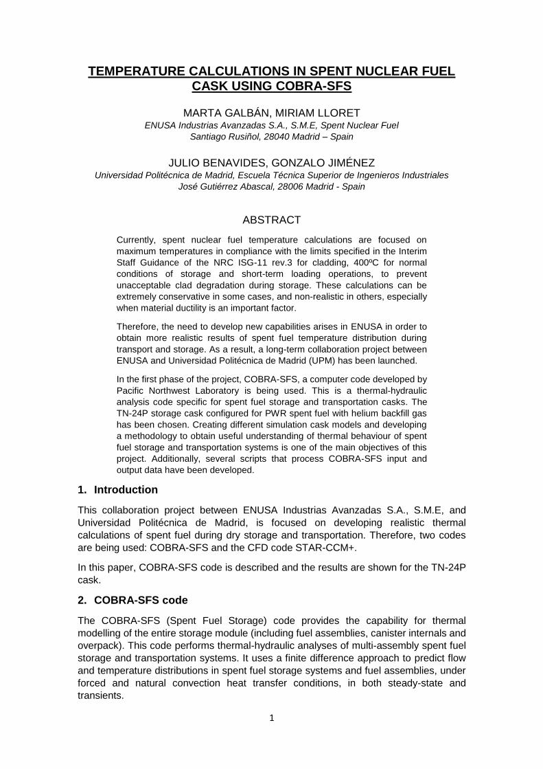
Figure 3. Subchannel definition
A number of simplifying assumptions are applied to these integral balance laws,
consistent with the intended application of the code, such as:
1. The flow is at sufficiently low velocity so that kinetic and potential energy are
negligible compared to internal thermal energy.
2. Work done by body forces and shear stresses is small compared to surface heat
transfer and convective energy transport in the energy equation.
3. Gravity is the only significant body force in the momentum equation.
4. The fluid is incompressible but thermally expandable, so that density and
transport properties vary only with the local temperature.
5. The radioactive energy source in the fuel is sufficiently decayed so that direct
energy deposition in the fluid is negligible, and there is no significant gamma
heating.
6. There is normally no lateral cross-coupling for momentum.
For more details about the COBRA-SFS code, structure and equations see [1].
3. The TN-24P test
3.1 Test conditions
In the first part of the project, the TN-24P cask has been chosen to be modeled due to
the extensive literature available and the published testing results performed by EPRI
[2].
The test consisted of loading the TN-24P cask with 24 PWR spent fuel assemblies from
Virginia Power´s Surry reactor. Testing was performed with vacuum, nitrogen and helium
backfill environment in horizontal and vertical cask orientation. In this paper only the
vertical orientation cask with helium backfill is analysed with an ambient temperature of
20ºC.
The Surry spent fuel assemblies used during testing are of a standard Westinghouse
15x15 rod design with fuel assembly decay heat generation rates totalled 20.6kW at the
start of testing and 20.3 kW at the end of testing for an average of 850 W per assembly.
Figure 4 shows the predicted axial decay heat profile assumed for each of the fuel
assemblies.

4
Figure 4. TN-24P test predicted axial decay heat profile [2]
For more details about the TN-24P test see [2].
3.2 Results
Once the COBRA-SFS input has been prepared based in data contained in [2] and with
the help of Python scripts developed for this container in particular (described in section
4), the code only takes a few minutes to generate the output data.
Figure 5 shows the peak temperature results on the hottest assembly (assembly 9, in
the center location in the basket, in the hottest rod, number 173) obtained with COBRA-
SFS code, compared to the measurements of the thermocouple (TC) in this assembly.
The code predicts very good results regarding maximum temperatures located in the
center of the axial height of the rod (220ºC), but in the upper and lower height of the rod
these temperatures have some differences compared with the measurements of the TC.
This could be a result of several possibilities, one the boundary conditions of the
experiment, there is no precise information about where the cask was located when the
experiment was performed in the warm shop, and the other option is due to how COBRA-
SFS models the upper and lower plenum (a single node where the gas pressure and
temperature is instantly mixed), this might explain the difference between temperatures
at the bottom of the cask and the upper parts of the assembly.
Figure 5. COBRA calculated Temperature (ºC) vs TC measured results

5
COBRA-SFS code has very good agreement regarding temperature results especially in
assemblies located in the center of the container as shown in Figures 5 and 6.
Figure 6. Temperature (ºC) in canister and assemblies
For the peripheral assemblies, predicted temperatures are slightly different compared to
measurements. In Figure 7, temperature results of two of the peripherals assemblies are
represented compared with the measured TC located in the assembly. In the graphic,
COBRA-SFS predicted results are approximately 10-20ºC above the TC measurements.
The TC measurement out of the profile at 4,4m height, is the temperature measured at
the top of the cask lid.
Figure 7. Peripheral assemblies temperature (ºC)
6
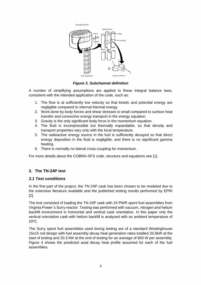
Trying to find the reasons for such difference, the helium flux behaviour inside the
canister was analysed in detail, coming up to the conclusion that the helium flux inside
the cask in COBRA-SFS code was not calculated properly, as it was found that all the
helium flux comes down only through two specific assemblies as shown in Figure 8.This
is not a realistic solution because initial and boundary conditions in the system are
symmetrical, so the helium flux behaviour should be symmetrical too. It was expected
that all outside assemblies (assemblies without rods) would act as channels for the
thermo-syphon closing the helium loop.
Figure 8. Flux velocity (mm/s) results per assembly
Therefore, one of the main goals in this part of the project is to solve this COBRA-SFS
distribution of helium flux inside the cask. In order to do this, parameter studies of
sensitivity are being performed and a new methodology is being developed due to this
flux disagreement in the code. Simulations with CFD code STAR-CCM+ are being
developed, with the aim of introducing STAR-CCM+ predicted flux results in the COBRA-
SFS input and analyse how this affects the results. The main issue CFD codes have is
the high computational cost to obtain the results, compared to using other codes such
as COBRA-SFS, therefore developing new capacities and methodology using mainly
COBRA-SFS code supported by STAR-CCM+ when necessary, is one of the goals
regarding this project.
4. COBRA-SFS: Python scripts
As described in section 1 of this paper, the COBRA-SFS input and output interface is
neither graphical nor particularly user friendly, therefore the need to develop scripts in
Python, that process COBRA-SFS input and output data in this project.
4.1 Input
To simplify the process of typing the entire input (a txt file), the first step is to create an
Excel matrix that represents the geometry of the model. The main input is defined by
three different matrix:
SLABS: this group represents the solid structure of the cask container and
thermal connections between them and the fluid.
CHAN: the fluid geometry is specified in this group.
7
RODS: rod geometry and thermal connections between them and the fluid are
defined.
Once these matrices are defined, a Python script processes the information and the main
input groups are automatically generated.
4.2 Output
The COBRA-SFS code output is a txt file, this file is structured very similar to the input
file, the results are shown by regions (subchannels, rods, solid structure and fluid)
depending on the height.
Processing this output is not simple or user friendly. In order to work with it, the user has
to import to a post-processing tool region by region (Excel, Matlab …). The scripts built
in Python 3.6 help the user process the output file and represent the data of interest as
a profile plot or coloured map. These scripts allow the user to see the main variables
such as pressure, enthalpy, temperature, density, mass flux, volume flux and velocity.
All these values can be seen at different heights.
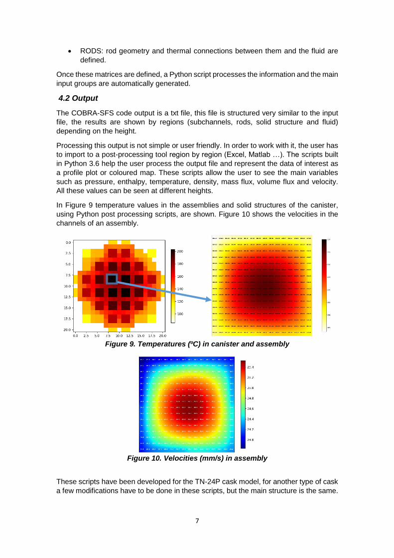
In Figure 9 temperature values in the assemblies and solid structures of the canister,
using Python post processing scripts, are shown. Figure 10 shows the velocities in the
channels of an assembly.
Figure 9. Temperatures (ºC) in canister and assembly
Figure 10. Velocities (mm/s) in assembly
These scripts have been developed for the TN-24P cask model, for another type of cask
a few modifications have to be done in these scripts, but the main structure is the same.
8
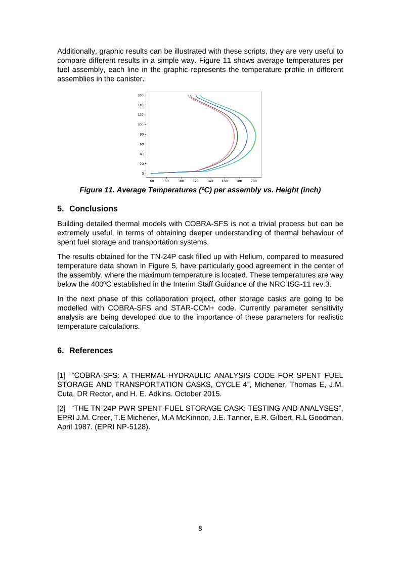
Additionally, graphic results can be illustrated with these scripts, they are very useful to
compare different results in a simple way. Figure 11 shows average temperatures per
fuel assembly, each line in the graphic represents the temperature profile in different
assemblies in the canister.
Figure 11. Average Temperatures (ºC) per assembly vs. Height (inch)
5. Conclusions
Building detailed thermal models with COBRA-SFS is not a trivial process but can be
extremely useful, in terms of obtaining deeper understanding of thermal behaviour of
spent fuel storage and transportation systems.
The results obtained for the TN-24P cask filled up with Helium, compared to measured
temperature data shown in Figure 5, have particularly good agreement in the center of
the assembly, where the maximum temperature is located. These temperatures are way
below the 400ºC established in the Interim Staff Guidance of the NRC ISG-11 rev.3.
In the next phase of this collaboration project, other storage casks are going to be
modelled with COBRA-SFS and STAR-CCM+ code. Currently parameter sensitivity
analysis are being developed due to the importance of these parameters for realistic
temperature calculations.
6. References
[1] “COBRA-SFS: A THERMAL-HYDRAULIC ANALYSIS CODE FOR SPENT FUEL
STORAGE AND TRANSPORTATION CASKS, CYCLE 4”, Michener, Thomas E, J.M.
Cuta, DR Rector, and H. E. Adkins. October 2015.
[2] “THE TN-24P PWR SPENT-FUEL STORAGE CASK: TESTING AND ANALYSES”,
EPRI J.M. Creer, T.E Michener, M.A McKinnon, J.E. Tanner, E.R. Gilbert, R.L Goodman.
April 1987. (EPRI NP-5128).