Embed Size (px)
Citation preview

Catalogue No.CAT-TE-5AU
PneumaticTelepneumaticProducts

D83Pneumatic
Contents Series Page
Electro-pneumatics interface modules - 4mm PS1E D84
Power valves - M5, G1/8, G1/4 PVL D90
Power valves - G1/8, G1/4, G1/2 PVD D108
Limit valves - 4mm PXC D122
Back pressure sensors - 4mm PWS D138
Control panel valves - 4mm PXB D143
Visual pressure indicators - 4mm PXV D151
Two-hand controls - 4mm PXP D152
Pneumatic sequencers - 4mm PSM D159
Pneumatic logic elements - 4mm PLL D161
Pneumatic timers - 4mm PRT D165
Pneumatic impulse counters - 4mm PCT D173
Pneumatic digital display timers - 4mm PCM D174
Contents

D84Pneumatic
PS1E111
Electropneumatic interface modules 3/2 - 4/2modules without solenoid valve
PS1E191
AB1G●●●●● AB1SR6
Characteristics :pages D87 & D88Dimensions :page D89 = At the time of printing, available on indent only.
Electropneumatic modules 3/2 (1)
One output. Module width 17,5 mm
Function Type of Pneumatic Reference WeightCharacteristics switching connection kg
Monostable Normally Instant Ø 4 mm PS1E111 0,052Visual indication of non-passing (NNP)pneumatic output(red for NNP Instant Ø 6 mm PS1E116 0,055yellow for NP)
Normally Instant Ø 4 mm PS1E121 0,052passing (NP)
Instant Ø 6 mm PS1E126 0,055
Low pressure electropneumatic modules 3/2 (1 to 8 bar)
One output. Module width 17,5 mm
Function Type of Pneumatic Reference WeightCharacteristics switching connection kg
Monostable Normally Instant Ø 4 mm PS1E311 0,052Visual indication of non-passing (NNP)pneumatic output(red for NNP)
Instant Ø 6 mm PS1E316 0,055
Electropneumatic modules 4/2 (1)
Two complementary outputs. Module width 2 x 17,5 mm
Function Type of Pneumatic Reference WeightCharacteristics switching connection kg
Bistable Normally Instant Ø 4 mm PS1E191 0,120Visual indication non-passing (NNP)of pneumatic output and(red for NNP normally Instant Ø 6 mm PS1E196 0,125yellow for NP) passing (NP)
Monostable Normally Instant Ø 4 mm PS1E181 0,120Visual indication non passing (NNP)of pneumatic output and(red for NNP normally Instant Ø 6 mm PS1E186 0,125yellow for NP) passing (NP)
Marking accessories
Description Reference Weightkg
Holder for 6 clip-on markers AB1SR6 0,006Sold in lots of 200
Clip-on marker strips Strip of 10 identical numerals AB1R●●●●● 0,002(state the number required)Strip of 10 identical letters AB1G●●●●● 0,002(state the letter required)
Sold in lots of 25 strips Strip of 10 + signs AB1R12 0,002of 10 markers Strip of 10 - signs AB1R13 0,002(1) To obtain a complete electropneumatic interface module, order :(1) 1 module without solenoid valve (e.g. : PS1E191) + 1 solenoid valve (e.g. : PS1E2302B)
When ordering 200 holders for clip-on markers, please state the exact reference.Example : 200 AB1SR6

D85Pneumatic
Electropneumatic interface modules 3/2 - 4/2solenoid valvesLED indicatorsmulti-subbasesspare parts
PS1E230●●●●●●●●●●
Characteristics :pages D87 & D88Dimensions :page D89
...
...
...
PS1E1620●●●●●
PVUH13156
...
...
= At the time of printing, available on indent only.
1 W - 1,2 VA plug-in solenoid valves
With spring return With indexable Withoutmanual control manual control manual control
12 V PS1E2302J PS1E2352J PS1E2392J24 V PS1E2302B PS1E2352B PS1E2392B48 V PS1E2302E PS1E2352E PS1E2392E24 V ~ 50-60 Hz PS1E2301B PS1E2351B PS1E2391B48 V ~ 50-60 Hz PS1E2301E PS1E2351E PS1E2391E115V~50Hz/120V~60Hz PS1E2301F PS1E2351F PS1E2391F230V~50Hz/240V~60Hz PS1E2301M PS1E2351M PS1E2391M
Suppressor and LED indicators
To be mounted between the solenoid valve and the interface module
Characteristics Circuit diagram Voltage Reference Weightkg
Indication 24 V and PS1E1620B 0,010by LED 50/60 Hz ~
48 V and PS1E1620E 0,010Sold in lots of 5 50/60 Hz ~
115 V ~ 50 Hz PS1E1511F 0,012120 V ~ 60 Hz230 V ~ 50 Hz PS1E1511M 0,012240 V ~ 60 Hz
Multi-subbases for solenoid actuators 3/2 PS1-E24●●● (1)
Operating pressure 0 to 10 bar
Chracteristics Connection Number Reference Weightof positions kg
With pressure 1 1/8" 2 PVUH13152 0,095common 2 M5
4 PVUH13154 0,150
6 PVUH13156 0,200
8 PVUH13158 0,255
10 PVUH131510 0,310
(1) Connectors for electrical connection : see chapter 9
Spare parts
Composition Base Reference Weightproduct kg
• Seals for electropneumatic interface modules 3/2 and 4/21 lot of 100 O-ring seals PS1E11● /E21●●● PPRL12 0,015between modules (pressure - exhaust) PS1E12● /E22●●●
PS1E18● /E28●●●
PS1E19● /E29●●●
1 lot of 50 seals PS1E11● /E21●●● PPRL13 0,008between modules 3/2 or 4/2 and coil PS1E23 PS1E12● /E22●●●
- 25 seals (type A) for modules 3/2 and 4/2 bistable PS1E18● /E28●●●
- 25 seals (type B) for modules 4/2 monostable PS1E19● /E29●●●
and bistable
• For plug-in solenoids type PS1E23●●●●●●●●●●
1 lot of 20 mounting blocks for mounting the solenoid PPRL14 0,011onto the pneumatic body if no suppressor or electricalindicator block is fitted
• Latching device for head and tail sets1 kit comprising : PS1E101● PPRL09 0,110- 20 hooks PS1E102●
- 20 screws- 20 springsWhen ordering : 5 suppressor blocks, please state the exact reference, example : 5 PS1E1620B;
1 lot of 20 mounting blocks, please state the exact reference, example : 1 PPRL14.

D86Pneumatic
Electropneumatic interface modules 3/2 - 4/2complete unitspressure supply modules
PS1E21102●●●●●
PS1E29102●●●●●
PS1E102 PS1E1038
...
...
...
...
Electropneumatic modules 3/2
One normally non-passing output with Ø 4 mm instant connection
Characteristics Voltage Reference Weightkg
Visual indication of 24 V PS1E21102B 0,095pneumatic output
48 V PS1E21102E 0,095Spring returnmanual control 24 V ~ 50/60 Hz PS1E21101B 0,095
Module width 48 V ~ 50/60 Hz PS1E21101E 0,09517,5 mm
115 V ~ 50 Hz / 120 V ~ 50 Hz PS1E21101F 0,095
230 V ~ 50 Hz / 240 V ~ 50 Hz PS1E21101M 0,095
Electropneumatic modules 4/2
Two complementary outputs with Ø 4 mm instant connections
Characteristics Voltage Reference Weight Reference Weightmonostable kg bistable kg
Visual indication of 24 V PS1E28102B 0,165 PS1E29102B 0,205pneumatic output
48 V PS1E28102E 0,165 PS1E29102E 0,205Spring returnmanual control 24 V ~ PS1E28101B 0,165 PS1E29101B 0,205
50/60 HzModule width 48 V ~ PS1E28101E 0,165 PS1E29101E 0,2052 x 17,5 mm 50/60 Hz
115 V ~ 50Hz PS1E28101F 0,165 PS1E29101F 0,205120 V ~ 60Hz230 V ~ 50Hz PSE28101M 0,165 PS1E29101M 0,205240 V ~ 60Hz
Head and tail sets - intermediate supply modules
For 3/2 and 4/2 interface modules
Description Pneumatic Characteristics Reference Weightconnection kg
Set for Instant 1 electrical common terminal PS1E101 0,100single air supply Ø 6 mm 1 main air supply portconnection 1 exhaust port
Set for Instant 1 electrical common terminal PS1E102 0,125double air supply Ø 6 mm 2 main air supply portsconnection 2 exhaust ports
Intermediate Tapped 1 air supply port PS1E1038 0,125air supply 1/8 BSP 1 exhaust portmodule (see description below) (1)
(1) When incorporated into a group of electropneumatic interface module, it enables :(1) - connected on the air supply, the reinforcement of this supply by external 1/8 BSP injection or the connection of
supplies with different pressures by interrupting the common pressure line ;(1) - connected to the exhaust side, a separation of the exhaust by product groups or an improvement in the flow rate
by direct exhaust to atmosphere through the 1/8 BSP port.The intermediate supply module is supplied complete with 4 interchangeable interconnection nozzles suitable for
a wide range of supply combinations.
: U.L. approved.
= At the time of printing, available on indent only.
Characteristics :pages D87 & D88Dimensions :page D89
See pages D84 and D85 for components to makeup these products.

D87Pneumatic
Electropneumatic interface modules 3/2 - 4/2characteristics
Specific characteristics
Voltage range andstandard voltages
Id (mA) (1) Operating - 15° < t < 0° 0° < t < 40° 40° < t < 60°Un (V) Hz min. max. min. max. min. max.
PS1E23●●●●● 2B (24 V ... ) 5 24 0,85 Un 1,10 Un 0,85 Un 1,10 Un 0,90 Un 1,05 Un
PS1E23●●●●● 2E (48 V ... ) 2,5 48 0,85 Un 1,10 Un 0,85 Un 1,10 Un 0,90 Un 1,05 Un
PS1E23●●●●● 1B 22 24~/50 0,85 Un 1,10 Un 0,85 Un 1,10 Un 0,90 Un 1,05 Un24 V ~ 50 - 60 Hz 24~/60 0,85 Un 1,15 Un 0,85 Un 1,15 Un 0,90 Un 1,05 Un
PS1E23●●●●● 1E 12 48~/50 0,85 Un 1,10 Un 0,85 Un 1,10 Un 0,90 Un 1,05 Un48 V ~ 50 - 60 Hz 48~/60 0,85 Un 1,10 Un 0,85 Un 1,10 Un 0,90 Un 1,05 Un
PS1E23●●●●● 1F 5 110~/50 0,85 Un 1,10 Un 0,85 Un 1,10 Un 0,90 Un 1,05 Un115 V ~ 50 Hz 120~/60 0,80 Un 1,10 Un 0,80 Un 1,10 Un 0,90 Un 1,05 Un120 V ~ 60 Hz 100~/50 0,90 Un 1,20 Un 0,90 Un 1,20 Un 0,95 Un 1,15 Un
110~/60 0,85 Un 1,15 Un 0,85 Un 1,15 Un 0,90 Un 1,10 Un120~/50 0,80 Un 1,05 Un 0,80 Un 1,05 Un 0,85 Un 1,05 Un100~/60 0,90 Un 1,25 Un 0,90 Un 1,25 Un 0,95 Un 1,05 Un
PS1E23●●●●● 1M 2 220~/50 0,85 Un 1,10 Un 0,85 Un 1,10 Un 0,90 Un 1,05 Un230 V ~ 50 Hz 240~/60 0,80 Un 1,10 Un 0,80 Un 1,10 Un 0,90 Un 1,05 Un240 V ~ 60 Hz 200~/50 0,90 Un 1,20 Un 0,90 Un 1,20 Un 0,95 Un 1,15 Un
220~/60 0,85 Un 1,15 Un 0,85 Un 1,15 Un 0,90 Un 1,10 Un240~/50 0,80 Un 1,05 Un 0,80 Un 1,05 Un 0,85 Un 1,05 Un200~/60 0,90 Un 1,25 Un 0,90 Un 1,25 Un 0,95 Un 1,05 Un
(1) Id = drop-out current in mA
Compatibility with programmable controllers
The solenoid valves are programmable controller compatible provided that leakage currents of the PLC outputs are lower than the drop-out current value.

D88Pneumatic
Electropneumatic interface modules 3/2 - 4/2characteristics
General characteristics
Interfaces 3/2 and 4/2 Low pressure interfaces 3/2 Solenoid valvesPS1E2●●●●●●●●●●●●●●●●●●●●●●●●● PS1E31●●●●● PS1E230●●●●●●●●●●
Operating pressure 3 to 8 bar 1 to 8 bar 0 to 10 bar
Permissible fluids air or neutral gas, 50 µm filtration, lubricated or not
Flow rate (in l/mn ANR) at 6 bar 200 200 29
kv 2 2 0,26
Operating temperature - 15° C to + 60° C - 15° C to + 60° C - 15° C to + 60° C
Storage temperature - 40° C to + 70° C - 40° C to + 70° C - 40° C to + 70° C
Response time 10 to 15 ms 10 to 15 ms 5 to 8 ms
Mechanical life (number ofoperations) with dry air at 6 barand at 20° C - Frequency 1 Hz 30 million 30 million 30 million
Vibration resistance conforming to section 19-2 of Bureau Veritas regulations
Materials - body : 6.6 polyamide, glass fibre impregnated- poppet : polyurethane- seal : nitrile
Connections : - pneumatic instant connections : : instant connections : threaded : M5Ø 4 or Ø 6 mm according to version Ø 4 or Ø 6 mm according to version
- electrical screw-clamp with built-in common screw-clamp with built-in common by plug-incommon earth common earth connector
Fixing on standard EN 50 022 omega rail on standard EN 50 022 omega rail by screw
Mounting positions all positions all positions all positions
Manual control yes yes yes
Operating duty 100 % 100 % 100 %
Maximum operatingfrequency 10 Hz 10 Hz 10 Hz
Rated insulation voltage 1500 V 1500 V 1500 V
Degree of protection IP 40 IP 40 IP 65- sealed : direct current = 1 W - alternating current = 1,2 VA
Consumption - inrush : alternating current = 2,5 VA
Standards NFC 79 300 NFC 79 300 NFC 79 300

D89Pneumatic
Electropneumatic interface modules 3/2 - 4/2dimensions
Electropneumatic interface modules 3/2
PS1E21102●●●●● with PS1E101 head and tail units
PS1E21102●●●●● with PS1E102 head and tail units
Electropneumatic interface modules 4/2
PS1E28●●●●● and PS1E29●●●●● with PS1E102 head and tail units
Multi-subbases
PVU-H1315●●●●●
PVU- a H13152 56 H13154 88 H13156 120 H13158 152 H131510 184
32 17,517,5 1417,5 9 67
76
78
indicator blockintermediate module
17,5 9 69
78
32n modules32 17,517,517,5
25
25
20 16 20
18
G 1/8"Ø 4,256
a
32 35 9 69
78
3235 35
78
4/2 monostable 4/2 bistable indicator block
omega rail
Ø 6 mm instantconnection

D90Pneumatic
PVLA112315B40
PVLA112315
With 0,9 W - 24 V miniature solenoid actuator with built-in indicator
With plug-in electrical connector, cable length : 2 m
Symbol Function Manual Connection Reference Weightcontrol kg
Bistable Spring Instant Ø 4 mm PVLA112304B40 0,070pressure / pressure return
Threaded M5 PVLA112315B40 0,070
Monostable Indexable Instant Ø 4 mm PVLA111304B50 0,060spring return
Threaded M5 PVLA111315B50 0,060
Without miniature solenoid actuator
Symbol Function Connection Reference Weightkg
Bistable Instant Ø 4 mm PVLA112304 0,050pressure / pressure
Threaded M5 PVLA112315 0,050
Monostable Instant Ø 4 mm PVLA111304 0,050spring return
Threaded M5 PVLA111315 0,050
With penumatic piloting connector
Symbol Function Manual Connection Reference Weightcontrol kg
Bistable Direct Instant Ø 4 mm PVLA112104 0,060pressure / pressure
Threaded M5 PVLA112115 0,060
Monostable Direct Instant Ø 4 mm PVLA111104 0,055spring return
Threaded M5 PVLA111115 0,065
Mounting
The valves are surface mounted using M4 screws, directly on the machine structure or on any other suitable support.Connections are carried out using either threaded fittings or directly using the incorporated instant connections.
...
4 2
5 31
4 2
5 31
4 2
5 31
4 2
5 31
4 2
5 314 1 12
4 2
5 314 1
PVLA112115
...
= At the time of printing, available on indent only.
Power valves 5/2 without subbase, size M5stand-alone versionelectrical piloting by 0,9 W miniature solenoid actuatorpneumatic pilotingair or neutral gas, 5 µm filtration, not lubricated
Modular piloting system :page D94Connections :page D100Characteristics :page D101Dimensions :page D104

D91Pneumatic
Power valves 5/2 without subbase, sizes 1/8" and 1/4"stand-alone versionpneumatic or electrical piloting (1)
PVLB112606
Size 1/8"
For mounting with 1 W / 1,2 VA miniature solenoid actuator or pneumatic connector
Symbol Function Connection Reference Weightkg
Bistable Instant Ø 6 mm PVLB112606 0,120pressure / pressure
Threaded 1/8" PVLB112618 0,120
Monostable Instant Ø 6 mm PVLB111606 0,125spring return
Threaded 1/8" PVLB111618 0,125
Monostable Instant Ø 6 mm PVLB113606 0,125differentialpressure return Threaded 1/8" PVLB113618 0,125
Size 1/4"
For mounting with 1 W / 1,2 VA miniature solenoid actuator or pneumatic connector
Symbol Function Connection Reference Weightkg
Bistable Instant Ø 8 mm PVLC112608 0,230pressure / pressure Threaded 1/4" PVLC112619 0,230
Threaded 3/8" PVLC112613 0,230
Monostable Instant Ø 8 mm PVLC111608 0,240spring return Threaded 1/4" PVLC111619 0,240
Threaded 3/8" PVLC111613 0,240
Monostable Instant Ø 8 mm PVLC113608 0,240differential Threaded 1/4" PVLC113619 0,240pressure return Threaded 3/8" PVLC113613 0,240
Size 1/4"
For mounting with 5 W / 6 VA solenoid actuator or pneumatic connector
Symbol Function Connection Reference Weightkg
Bistable Instant Ø 8 mm PVLC112408 0,240pressure / pressure
Threaded 1/4" PVLC112419 0,240
Monostable Instant Ø 8 mm PVLC111408 0,250spring return
Threaded 1/4" PVLC111419 0,250
Monostable Instant Ø 8 mm PVLC113408 0,250differentialpressure return Threaded 1/4" PVLC113419 0,250
(1) Piloting control of a power valve can be either :(3) - pneumatic by mounting one or two pilot connectors with Ø 4 mm instant connections ;(3) - electrical by mounting one or two 1 W or 5 W solenoid actuators.(3) The modularity of this piloting system is described on page D94 and the accessories are shown on pages D96 and D97.
PVLC112619
Modular piloting system :page D94Connections :page D100Characteristics :pages D102 & D103Dimensions :pages D105 & D106
4 2
5 314 1 12
4 2
5 314 1
12
4 2
5 314 1
4 2
5 314 1
12
4 2
5 314 1
4 2
5 314 1 12
4 2
5 314 1 12
4 2
5 314 1
4 2
5 314 1
12
= At the time of printing, available on indent only.

D92Pneumatic
With 0,9 W - 24 V miniature solenoid actuator with built-in indicator
With plug-in electrical connector, cable length : 2 m
Symbol Function Manual Connection Reference Weightcontrol kg
Bistable Spring Instant Ø 4 mm PVLA122304B40 0,055pressure / pressure return
Threaded M5 PVLA122315B40 0,055
Monostable Indexable Instant Ø 4 mm PVLA121304B50 0,045spring return
Threaded M5 PVLA121315B50 0,045
Without miniature solenoid actuator
Symbol Function Connection Reference Weightkg
Bistable Instant Ø 4 mm PVLA122304 0,035pressure / pressure
Threaded M5 PVLA122315 0,035
Monostable Instant Ø 4 mm PVLA121304 0,035spring return
Threaded M5 PVLA121315 0,035
With pneumatic piloting connector
Symbol Function Manual Connection Reference Weightcontrol kg
Bistable Direct Instant Ø 4 mm PVLA122104 0,045pressure / pressure
Threaded M5 PVLA122115 0,045
Monostable Direct Instant Ø 4 mm PVLA121104 0,040spring return
Threaded M5 PVLA121115 0,040
(1) Each power valve is supplied complete with two threaded rods for making up the tie rod assembly.
PVLA122315
PVLA122315B40
4 2
5 31
4 2
5 31
4 2
5 31
4 2
5 31
4 2
5 314 1 12
4 2
5 314 1
PVLA122115
Power valves 5/2 without subbase, size M5stacking versionelectrical piloting by 0,9 W miniature solenoid actuatorpneumatic pilotingair or neutral gas, 5 µm filtration, not lubricated
...
= At the time of printing, available on indent only.
Modular piloting system :page D94Connections :page D100Characteristics :page D101Dimensions :page D104

D93Pneumatic
Size 1/8"
For mounting with 1 W / 1,2 VA solenoid actuator or pneumatic connector
Symbol Function Connection Reference Weightkg
Bistable Instant Ø 6 mm PVLB122606 0,090pressure / pressure Threaded 1/8" PVLB122618 0,090
Monostable Instant Ø 6 mm PVLB121606 0,100spring return Threaded 1/8" PVLB121618 0,100
Monostable Instant Ø 6 mm PVLB123606 0,100differential Threaded 1/8" PVLB123618 0,100pressure return
Size 1/4"
For mounting with 1 W / 1,2 VA miniature solenoid actuator or pneumatic connector
Symbol Function Connection Reference Weightkg
Bistable Instant Ø 8 mm PVLC122608 0,185pressure / pressure Threaded 1/4" PVLC122619 0,185
Threaded 3/8" PVLC122613 0,185
Monostable Instant Ø 8 mm PVLC121608 0,200spring return Threaded 1/4" PVLC121619 0,200
Threaded 3/8" PVLC121613 0,200
Monostable Instant Ø 8 mm PVLC123608 0,200differential Threaded 1/4" PVLC123619 0,200pressure return Threaded 3/8" PVLC123613 0,200
Size 1/4"
For mounting with 5 W / 6 VA solenoid actuator or pneumatic connector
Symbol Function Connection Reference Weightkg
Bistable Instant Ø 8 mm PVLC122408 0,190pressure / pressure
Threaded 1/4" PVLC122419 0,190
Threaded 3/8" PVLC122413 0,190
Monostable Instant Ø 8 mm PVLC121408 0,205spring return
Threaded 1/4" PVLC121419 0,205
Threaded 3/8" PVLC121413 0,205
Monostable Instant Ø 8 mm PVLC123408 0,205differentialpressure return Threaded 1/4" PVLC123419 0,205
Threaded 3/8" PVLC123413 0,205
(1) Each power valve is supplied complete with two threaded rods for making up the tie rod assembly (mountingpage D99).
(2) Piloting control of a power valve can be either :- pneumatic by mounting one or two pilot connectors with Ø 4 mm instant connections;- electrical by mounting one or two 1 W or 5 W solenoid actuators.The modularity of this piloting system is described on page D94 and the accessories are shown on pagesD96 and D97.
Power valves 5/2 without subbase, sizes 1/8" and 1/4"stacking version (1)for electrical or pneumatic piloting (2)
PVLC121408
Modular piloting system :page D94Connections :page D100Characteristics :pages D102 & D103Dimensions :pages D105 & D106
4 2
5 314 1 12
4 2
5 314 1
12
4 2
5 314 1
4 2
5 314 1 12
4 2
5 314 1
12
4 2
5 314 1
4 2
5 314 1
12
4 2
5 314 1
4 2
5 314 1 12
= At the time of printing, available on indent only.
PVLB122606
PVLC122619

D94Pneumatic
Power valves 5/2 without subbasemodular piloting system
1/8"
1/4"
1/4"
- power : 1 W1,2 VA ~
- electricalconnector : 15 x 15 mm
M5
M5, 1/8" and 1/4" sizes
Basic component Pneumatic pilotingconnectors
- power : 0,9 W...
Pilotingsolenoid actuators
- power : 5 W6 VA ~
- electricalconnector : 22 x 30 mm
...
PVLA1●●●●●●●●●● 3●●●●●●●●●●
M5
PVAJ●●●●●●●●●●●●●●●●●●●●
PVAP11●●●●●
PVAP12●●●●●

D95Pneumatic
Power valves 5/2 without subbase, size M5electrical piloting
power valve solenoid actuators
= At the time of printing, available on indent only.
0,9 W miniature solenoid actuators with built-in indicator
Type Voltage Actuator only Actuator with unwired 10 Actuator with pre-wired 10 connector - Cable length L=connector 2 m 5 m 10 m
References (IP 40 models)
Spring return 12 V ... PVAJ1302J9 PVAJ1302J PVAJ1302J0 PVAJ1302J1 PVAJ1302J2manual
control 24 V ... PVAJ1302B9 PVAJ1302B PVAJ1302B0 PVAJ1302B1 PVAJ1302B2
Indexable 12 V ... PVAJ1352J9 PVAJ1352J PVAJ1352J0 PVAJ1352J1 PVAJ1352J2manualcontrol 24 V ... PVAJ1352B9 PVAJ1352B PVAJ1352B0 PVAJ1352B1 PVAJ1352B2
Without 12 V ... PVAJ1392J9 PVAJ1392J PVAJ1392J0 PVAJ1392J1 PVAJ1392J2manualcontrol 24 V ... PVAJ1392B9 PVAJ1392B PVAJ1392B0 PVAJ1392B1 PVAJ1392B2
To order solenoid actuators with built-in overvoltage limiter (for control circuit protection) :replace the first digit in the numerical part of the reference by 5. Example : PVAJ5352B

D96Pneumatic
Power valves 5/2 without subbase, sizes 1/8" and 1/4"for pneumatic piloting or electrical piloting by 1W / 1,2VA miniature solenoid actuators
piloting modules
PVAP171
PVAP111
Electrical connector
Connectors for pneumatic piloting
Mounting Type of Reference Weightconnection kg
Mounting on the same Instant Ø 4 mm PVAP111 0,007plane as the 1 W / 1,2 VAsolenoid actuator
Threaded M5 PVAP115 0,002
Intermediate piloting connectors
For mounting between the PVAH24●●●●● solenoid actuator and the PVLB●●●●● or PVLC● ● ● ● ● power valve 5/2 mounted on omega rail
Description Type of Reference Weightconnection kg
For pneumaticpiloting Straight, instant Ø 4 mm PVAP171 0,040of the power valve
For external supply Swivel, instant Ø 4 mm PVAP161 0,040of the 1 W / 1,2 VAminiature solenoid actuators
Straight, instant Ø 4 mm PVAP163 0,040
With LED 3-pin, 9.4 mm PESC2020BWithout LED 3-pin, 9.4 mm PESC10
= At the time of printing, available on indent only.
1 W / 1,2 VA solenoid actuators
Type Voltage Actuator only Actuator with unwired Actuator with pre-wired 15 x 15 connector - Cable length L= 15 x 15 connector 2 m 5 m 10 m
References
Without 12 V ... PS1E2492J - - - -
manual 24 V ... PS1E2492B PVAH2492B PVAH2492B0 PVAH2492B1 PVAH2492B2
control 48 V ... PS1E2492E PVAH2492E PVAH2492E0 PVAH2492E1 PVAH2492E2
24 V ~ 50-60 Hz PS1E2491B PVAH2491B PVAH2491B0 PVAH2491B1 PVAH2491B2
48 V ~ 50-60 Hz PS1E2491E PVAH2491E PVAH2491E0 PVAH2491E1 PVAH2491E2
115 V ~ 50 Hz PS1E2491F PVAH2491F PVAH2491F0 PVAH2491F1 PVAH2491F2 120 V ~ 60 Hz
230 V ~ 50 Hz PS1E2491M PVAH2491M PVAH2491M0 PVAH2491M1 PVAH2491M2 240 V ~ 60 Hz
Electrical connector without LED: PESCIO.Electrical connector with 24VAC/DC LED: PESC2020B
Piloting connector
PVAP161

D97Pneumatic
Power valves 5/2 without subbase, size 1/4"for pneumatic piloting or electrical piloting by 5 W / 6 VA solenoid actuators
piloting modules
5 W / 6 VA solenoid actuators
Type Voltage Actuator only Actuator with unwired Actuator with pre-wired 22 x 30 connector - Cable length L=22 x 30 connector 2 m 5 m 10 m
References
12 V ... PVAF192J - - - -
24 V ... PVAF192B PVAF102B (1) PVAF102B0 PVAF102B1 PVAF102B2
48 V ... PVAF192E PVAF102E (1) PVAF102E0 PVAF102E1 PVAF102E2
24 V ~ 50-60 HZ PVAF191B PVAF101B PVAF101B0 PVAF101B1 PVAF101B2
48 V ~ 50-60 HZ PVAF191E PVAF101E PVAF101E0 PVAF101E1 PVAF101E2
115 V~ 50 Hz PVAF191F PVAF101F PVAF101F0 PVAF101F1 PVAF101F2120 V ~ 60 Hz
230 V ~ 50 Hz PVAF191M PVAF101M PVAF101M0 PVAF101M1 PVAF101M2240 V ~ 60 Hz
240 V ~ 50 Hz - PVAF101U PVAF101U0 PVAF101U1 PVAF101U2
(1) Versions available for use in explosive atmospheres :- conforming to certification LCIE 866115 X,- electrical equipment conforming to harmonised European standardsEN 500 14 dated March 1977 (NFC23 514 dated May 1982)EN 500 19 dated March 1977 (NFC23 519 dated May 1982)- marking code EExe II T4 (consult your local sales office).
Connector for pneumatic piloting
Mounting Type of Reference Weightconnection kg
Mounting Instant Ø 4 mm PVAP121 0,004in the same plane elbowas the 5 W / 6 VAsolenoid actuator
Instant Ø 4 mm PVAP122 0,007swivel
Threaded M5 PVAP125 0,004
With LED, DIN43650-B, 24VDC 9125998003With LED, DIN43650-B, 110VAC/DC 9125998007Without LED, DIN43650-B, up to 240VAC/DC 9141152500
PVAP122
= At the time of printing, available on indent only.
Electrical connector

D98Pneumatic
Power valves 5/2 without subbase head and tail sets
Dimensions :pages D104 and D107
Head and tail sets
For stacking power valves 5/2, sizes M5, 1/8 and 1/4
Type of Description For power valves Common port Reference Weightmounting size size kg
Omega rail Single supply M5 1/8" PVLA1718 0,065mounting head and tail set 1/8" 1/4" PVLB1719 0,175
1/4" 3/8" PVLC1713 0,195
Dual air supply M5 1/4" PVLA1728 0,080head and tail set 1/8" 1/4" PVLB1729 0,245
1/4" 3/8" PVLC1723 0,285
Surface Dual air supply 1/8" 1/8" PVLB1818 0,200mounting head and tail set 1/4" 1/4" PVLC1819 0,225
Dual air supply 1/8" 1/8" PVLB1828 0,260head and tail set 1/4" 1/4" PVLC1829 0,280
Mounting
● Omega rail mountingDual air supply
This mounting arrangement can be used to supply up to 16 valves.The air supply (1) and exhaust ports (3 and 5) are duplicated.
With single air supply
This mounting arrangement is recommended for small combinations(maximum eight power valves), it produces space saving by using only oneair supply module.
●●●●● Surface mountingFor single or dual air supply (1/8" threaded ports for 1/8" power valves and1/4" for 1/4" power valves).
This mounting does not use Omega rail. Particularly compact, it isrecommended for combinations of only a few power valves (maximum 5valves) but the supply commons 1-3-5 are not oversize.
assemblyscrewsscrews for clamping
on omega rail
screws for clampingon omega rail
assemblyscrews
holes forfixing screws
●●●●● Mounting procedure for stacking power valves mounted onomega rail.
Mount the power valves on the tie rods.
●●●●● Procedure for surface mounting of stacking power valves
The head module is fixed by 2 screws and provides the fixed point ofthe combination. The other mounting operations are identical to thosedescribed above.
Clip-on thetail module
Assemble thetwo parallel
tie rods
PVLB1729 PVLB1818
Tightenthe finalassembly
Clip-on andlock thetail module
= At the time of printing, available on indent only.

D99Pneumatic
Power valves 5/2 without subbasehead and tail sets
Dimensions :pages D104 and D107
Components for stacking two sizes of power valve
Description Type of Size of Reference Weightmounting power valves kg
Components for stacking 2 sizes : "transfer/take-off" module and corresponding head and tail set
Kit for stacking power valves : On omega rail M5 and 1/8" PVULBA118 0,120- one "transfer/take-off" module- two head and tail sets with one in each size. 1/8" and 1/4" PVULCB119 0,642
Components for intermediate supply
Intermediate supply module On omega rail 1/8" PVULBB118
1/4" PVULCC119Components for commons sealing
Kit for sealing the commons : M5 PVLA1901 0,020- 3 common blanking plugs- 2 drilled and threaded rods 1/8" PVLB1901 0,035- 2 screws for extended tie rods
1/4" PVLC1901 0,065
Spare parts
Composition Size of Base Reference Weightpower valve component kg
- Seals for common supply pressure and exhaust common ports1 lot of 30 0-ring seals 1/8" PVLB17●● PPRV23 0,009
PVLB18●●
PVLB12●●●●
1/4" PVLC17●● PPRV24 0,017PVLC18●●
PVLC12●●●●
- Seals for pneumatic piloting or solenoid actuator connectors1 lot of 50 O-ring seals PVAP122 PPRV25 0,007for pneumatic piloting connectors PVAP121type PVAP12● PVAP1251 lot of 20 seals PVLB11● 6●● PPRV20 0,004for solenoid actuator type PVAH24●●● PVLB12● 6●●
and pneumatic piloting connector PVLC11● 6●●
type PVAP11● PVLC12● 6●●
- Fixing accessories1 lot of 20 hooks PVLB17●● PPRL09 0,110for head and tail modules PVLC17●●
1 lot of 10 stacking rods PVLB12●●●● PPRV21 0,040for 1/8" power valves1 lot of 10 stacking rods PVLC12●●●● PPRV22 0,058for 1/4" power valves
Commons sealing and power valve stacking
Commons sealing Power valve stacking
Example 1 : two different pressures P1 andP2 can supply the same bank of power val-ves, the exhausts remaining common.
Example 2 : complete isolation of thecommons in the same bank of power valves: supply pressure and exhaust commons.
Example 3 : isolation of the exhaust commonsin the same bank of power valves, with thesupply pressure remaining common.
When ordering : 1 lot of 30 O-ring seals for supply pressure and exhaust common ports,please state the exact reference. Example : 1 PPRV23
PVULCB119
PV●●●●● 1901
PPRV2●●●●●
tie rods
3
1
5
3
1
5
3
1
5
power valves
head module
transfer/take-offmodule tail module
Example : two sizes of stacking power valves (maximum 16 foreach size), grouped in a bank mounted on omega rail with airsupply at the centre and at each end.
= At the time of printing, available on indent only.

D100Pneumatic
Stand alone power valves
Connection using straight threaded fitting Direct connection
Stacking power valves
Fittings for connecting the outlet ports on a single side
Fittings for connecting the outlet ports on both sides
Ports sealing
Use of a port blanking plug to obtain a single outlet power valve (3/2)
Power valves 5/2 without subbaseconnections
Power valves withthreaded ports
Power valves withinstant connections
A bank of stacking power valves has alarge number of outlet ports whichneed to be connected to the cylinders.
A range of elbow fittings makes theseconnections easier.
It is possible :- either to make connections on a
single side using connectionaccessories which enable two-levelsof output con-nection ;
- or to make connections on both sidesof a bank.
Chapter 8 gives details of the requiredaccessories.
With the power valves mounted flat, theconnections are normally straight, forboth threaded ports and integratedinstant connections.
Push-in or threaded blanking plugsenable the unused ports to be blockedoff.

D101Pneumatic
Power valves 5/2 without subbase, size M5characteristics
6
4
2
0100 200 300
PS (bar)
l/mn (ANR)
PE
PE
PE
General characteristics
- pneumatically piloted power valve : on port 1 P = 2 to 10 barOperating pressure - electrically piloted power valve : on port 1 P : bistable = 2 to 10 bar ; monostable = 3 to 10 bar
Permissible fluids air or neutra gas, 5 µm filtration, not lubricated
Flow rates (in l/mn ANR)
kv 2,2
Operating temperature - 15° C to + 60° C
Storage temperature - 40° C to + 70° C
Mechanical life (number of operations)at 6 bar with dry air, 50µm filteredand at 20° C - Frequency 1 Hz 30 million
Vibration resistance conforming to section 19-2 of Bureau Veritas regulations
Materials - body : polyamide 6,6 glass fibre impregnated - seals : polyurethane
Connections - instant connections : Ø 4 mm - threaded connection : M5
Max. connector tightening torque M5 = 0,5 Nm ; 1/8" = 10 Nm
Fixing on omega rail or machine structure
Mounting position all positions
Specific characteristics
Bistable power valves with pneumatic control Monostable with spring return
Response time at 6 bar 15 ms 20 ms
Pilot pressure at 6 bar 1,5 bar 2,5 bar
Depilot pressure at 6 bar - 1 bar
Maximum operating frequency 10 Hz 10 Hz
Degree of protection IP 65 IP 65
Manual control direct direct
Bistable power valves with pneumatic control Monostable with spring return
Response time 15 ms 25 ms
Consumption - DC : sealed = 0,9 W - DC : sealed = 0,9 W
Voltage range 0,9 to 1,05 Un 0,9 to 1,05 Un
Standard voltages 12 V ... ; 24 V ... 12 V ... ; 24 V ...
Operating duty 100 % 100 %
Maximum operating frequency 10 Hz 5 Hz
Rated insulation voltage 660 V 660 V
Degree of protection IP 40 IP 40
Manual control spring return indexable
Standards NFC 79 300 NFC 79 300
PE : input pressurePS : output pressure

D102Pneumatic
Power valves 5/2 without subbase, sizes 1/8" and 1/4"characteristics
1
400
2
3
4
5
6
800 1200 1600 2000
PE
PE
PE
l/mn(ANR)
PS(bar)
General characteristics
Power valve 1/8" Power valve 1/4"
Operating pressure - peumatically piloted power valve : on port 1 P = 2 to 10 bar- electrically piloted power valve : on port 1 P =
● bistable : 2 to 10 bar● monostable : 3 to 10 bar
Permissible fluids air or neutral gas 50 µm filtration, lubricated or not
Flow rates (en il/mn ANR)
kv - Ø 6 mm instant connections = 6 - Ø 8 mm instant connections = 12- 1/8" threaded connection = 8 - 1/4" threaded connection = 16
Operating temperature - 15° C to + 60° C - 15° C to + 60° C
Storage temperature - 40° C to + 70° C - 40° C to + 70° C
Mechanical life (number of operations)at 6 bar with dry air, 50µm filteredand at 20° C - Frequency 1 Hz 30 million 30 million
Vibration resistance conforming to section 19-2 of Bureau Veritas conforming to section 19-2 of Bureau Veritas
Material - body : polyamide 6,6 glass fibre impregnated - body : polyamide 6,6 glass fibre impregnated- seals : polyurethane - seals : polyurethane
Connections - Ø 6 mm instant connections - Ø 8 mm instant connections- 1/8" threaded connection - 1/4" threaded connections
Maximum connector 1/8" = 10 Nm 1/8" = 10 Nmtightening torque 1/4" = 20 Nm 1/4" = 20 Nm
3/8" = 55 Nm 3/8" = 55 Nm
Fixing On omega rail or machine structure On omega rail or machine structure
Mounting position all positions all positions
1
200
2
3
4
5
6
400 600 800 1000
PE
PE
PE
l/mn(ANR)
PS(bar)
PE : input pressurePS : output pressure
PE : input pressurePS : output pressure
threaded connector
instant connector

D103Pneumatic
Power valves 5/2 without subbase, sizes 1/8" and 1/4"characteristics
Specific characteristics
Power valves with pneumatic control
Size 1/8" Size 1/4"Monostable Monostable Monostable Monostable
Bistable spring return differential return Bistable spring return differential return
Response time (at 6 bar) 8 ms 14 ms 14 ms 11 ms 25 ms 31 ms
Pilot pressure (at 6 bar) 1,5 bar 3 bar 4 bar 1,5 bar 3 bar 4 bar
Depilot pressure (at 6 bar) - 1 bar 1,5 bar - 1 bar 1,5 bar
Maximum operating frequency 10 Hz 5 Hz 5 Hz 10 Hz 5 Hz 5 Hz
Degree of protection IP65 IP65 IP65 IP65 IP65 IP65
Manual control spring return indexable indexable spring return indexable indexable
Power valves with electrical control
Size 1/8" Size 1/4"Monostable Monostable Monostable Monostable
Bistable spring return differential return Bistable spring return differential return
Response time with PVA-H (at 6 bar) 12 ms 22 ms 23 ms 17 ms 39 ms 42 ms
Response time with PVA-F (at 6 bar) - - - 15 ms 25 ms 33 ms
Consumption with PVA-H- sealed 1 W / 1,2 VA 1 W / 1,2 VA 1 W / 1,2 VA 1 W / 1,2 VA 1 W / 1,2 VA 1W / 1,2 VA- inrush 3,5 VA 3,5 VA 3,5 VA 3,5 VA 3,5 VA 3,5 VA
Consumption with PVA-F- sealed 5 W / 6 VA 5 W / 6 VA 5 W / 6 VA 5 W / 6 VA 5 W / 6 VA 5 W / 6 VA- inrush 20 VA 20 VA 20 VA 20 VA 20 VA 20 VA
Voltage range 0,9 to 1,05 Un
Standard voltages 24 V ... , 48 V ... , 24 V ~, 48 V ~, 115 V ~, 230 V ~
Operating duty 100 % 100 % 100 % 100 % 100 % 100 %
Maximum operating frequency 10 Hz 5 Hz 5 Hz 10 Hz 5 Hz 5 Hz
Rated insulation voltage 1500 V 1500 V 1500 V 1500 V 1500 V 1500 V
Degree of protection IP65 IP65 IP65 IP65 IP65 IP65
Manual control spring return indexable indexable spring return indexable indexable
Standards NFC 79 300 NFC 79 300 NFC 79 300 NFC 79 300 NFC 79 300 NFC 79 300
D104Pneumatic
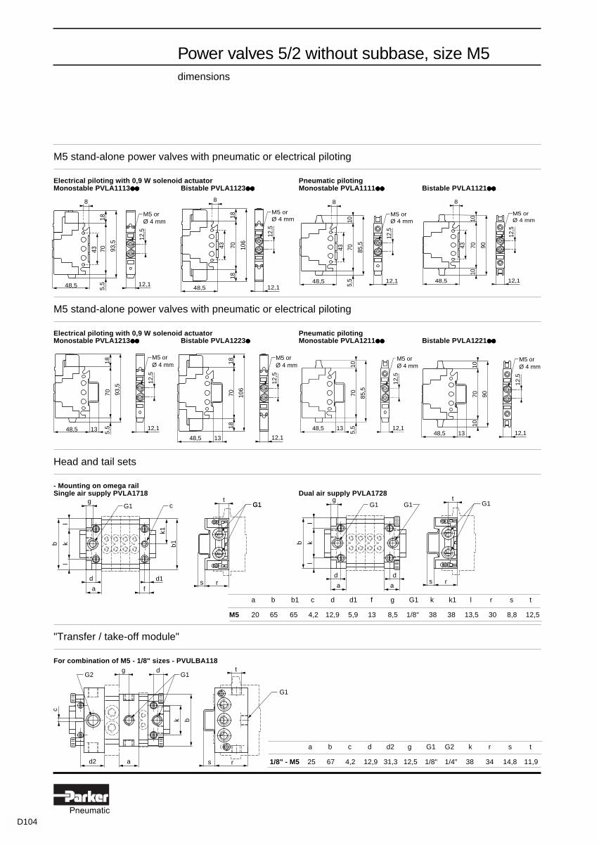
Power valves 5/2 without subbase, size M5dimensions
M5 stand-alone power valves with pneumatic or electrical piloting
Electrical piloting with 0,9 W solenoid actuator Pneumatic pilotingMonostable PVLA1113●●●●●●●●●● Bistable PVLA1123●●●●●●●●●● Monostable PVLA1111●●●●●●●●●● Bistable PVLA1121●●●●●●●●●●
M5 stand-alone power valves with pneumatic or electrical piloting
Electrical piloting with 0,9 W solenoid actuator Pneumatic pilotingMonostable PVLA1213●●●●●●●●●● Bistable PVLA1223●●●●● Monostable PVLA1211●●●●●●●●●● Bistable PVLA1221●●●●●●●●●●
Head and tail sets
- Mounting on omega railSingle air supply PVLA1718 Dual air supply PVLA1728
"Transfer / take-off module"
For combination of M5 - 1/8" sizes - PVULBA118
a b c d d2 g G1 G2 k r s t
1/8" - M5 25 67 4,2 12,9 31,3 12,5 1/8" 1/4" 38 34 14,8 11,9
a b b1 c d d1 f g G1 k k1 l r s t
M5 20 65 65 4,2 12,9 5,9 13 8,5 1/8" 38 38 13,5 30 8,8 12,5
48,5 5,5
7018
93,5
12,1
12,5
M5 or Ø 4 mm
8
43
48,5
7018
106
12,1
12,5
M5 orØ 4 mm
18
8
43
48,5 5,5
7010
85,5
12,1
12,5
M5 or Ø 4 mm
8
43
48,5
7010
90
12,1
12,5
M5 or Ø 4 mm
10
8
43
48,5
7010
90
12,1
12,5
M5 orØ 4 mm
10
13
gG1
b kl
l
d
a
d
a
G1
s r
tG1G1g
G1
b kl
l
d
a
d1
f
k1
b1
c
s r
tG1
c
d2 a
k b
dgG1G2
t
s r
G1
48,5 5,5
7018
93,5
12,1
12,5
M5 orØ 4 mm
13
48,5
7018
106
12,1
12,5
M5 or Ø 4 mm
18
13
48,5
5,5
7010
85,5
12,1
12,5
M5 orØ 4 mm
13

D105Pneumatic
Power valves 5/2 without subbase, size 1/8"dimensions
Stand-alone power valves 1/8" without piloting accessories
Monostable PVLB1116●●●●●●●●●● , PVLB1136●●●●●●●●●● Bistable PVLB1126●●●●●●●●●●
Stacking power valves 1/8" with pneumatic or electrical piloting
Monostable PVLB1216●●●●●●●●●● , PVLB1236●●●●●●●●●●
Bistable PVLB1226●●●●●●●●●●
61 12
1/8" BSPor
Ø6mm
9513
108 20
18
61 12
9113
117
13
1/8" BSPor
Ø6mm
20
18
61 12
9555
150
1/8" BSPor
Ø6mm
20
18
61 12
9155
210
55
1/8" BSPor
Ø6mm
20
18
61
95 20
18
1616
26,5
26,5
22Ø4,2
1/8"BSP 70
91 20
18
26,5
26,5
22Ø4,2
Ø6mm
1616

D106Pneumatic
Power valves 5/2 without subbase, size 1/4"dimensions
Stand-alone power valves 1/4" without piloting accessories
Monostable PVLC1116●●●●●●●●●● , PVLC1136●●●●●●●●●● , PVLC1114●●●●●●●●●● , PVLC1134●●●●●●●●●● Bistable PVLC1126●●●●●●●●●● , PVLC1124●●●●●●●●●●
1/4"BSP 3/8" BSPa 73 88
Stacking power valves 1/4" with pneumatic or electrical control
With 1 W solenoid actuator and suitable pneumatic connectorMonostable PVLC1216●●●●●●●●●● , PVLC1236●●●●●●●●●● Bistable PVLC1226●●●●●●●●●●
1/4"BSP 3/8" BSPb 73 77
With 5W solenoid actuator and suitable pneumatic connectorMonostable PVLC1214●●●●●●●●●● , PVLC1234●●●●●●●●●● Bistable PVLC1224●●●●●●●●●●
25
25
a
124
1/4"BSP
or 3/8" BSP
2020 33
33
Ø4,2 25
25
25
83
120
Ø8 mm
2020
3333
Ø4,2 25
b 11
117
143
21
25
25
21
b 11
120
220
50
25
25
50
1/4" BSP, 3/8" BSP
orØ8mm 1/4" BSP,
3/8" BSPor
Ø8mm
b 11
124 14
5
21
25
25
b 11
124 17
4
50
25
25
1/4" BSP, 3/8" BSP
orØ8mm
1/4" BSP, 3/8" BSP
orØ8mm
b 11
123
136
13
25
25,5
b 11
123
178
55
25
25,5
1/4" BSP, 3/8" BSP
orØ8mm
1/4" BSP, 3/8" BSP
orØ8mm
b 11
117
143
13
25
25,5
13
b 11
123
227
55
25
25,5
55
1/4" BSP, 3/8" BSP
orØ8mm
1/4" BSP, 3/8" BSP
orØ8mm

D107Pneumatic
Power valves 5/2 without subbase, sizes 1/8" and 1/4"dimensions
G1
a
b1
d g
n modules f
t
rs
G1
G1
a1
b1
n modules fØ4,2
K
G2V
uu
a a1 b b1 c d f g G1 G2 k r s t u v
1/8" 38 16 83 70 4,2 10 8 12 1/4" 1/8" 17,3 44 9 11 16 25
1/4" 38 20 108 100 4,2 10 8 12 3/8" 1/4" 63,5 55 9 13 20 30
a b c g G1 G2
1/4" - 1/8" 25 100 4,2 12 1/4" 3/8"
a b G
1/8" 18 75 1/8"
1/4" 25 100 1/4"
12
G
a
b
1212
G1
a
d g
n modules a
b
c
G1
Ø5 screwdriver
Allen key(1/8" : 3 mm-1/4" : 4 mn)
Head and tail sets
Single air supply Dual air supplyPVLB1719, PVLC1713, mounting on omega rail PVLB1729, PVLC1723, mounting on omega rail
Single air supplyPVLB1818, PVLC1819, "stack mounting"
"Transfer / take-off" module, intermediate supply module
For combination of sizes 1/4" - 1/8" - PVULCB119 PVUL-BB118 - PVU-LCC119
Intermediate piloting connectors
PVAP171 PVAP161 PVAP163
b
n modules n modulesg
c
g
G 2 G 1 G 1
c
aØ5 screwdriver

D108Pneumatic
Power valves 4/2 on stacking subbaseswith ceramic switchingPilot supply :
pages D112 and D113Utilisation :page D114Characteristics :pages D116 and D117Dimensions :page D120
Size 1/8"
Pneumatic or electrical piloting with auxiliary manual control (1)
Symbol Connection Piloting Function Reference Weightkg
1P Threaded Pneumatic Bistable PVDB142128 0,2503 1/8 BSP42 Monostable PVDB141128 0,245
14 Instant12 swivel Electrical by Bistable PVDB142428 0,260
Ø 4 mm PVAF10●●
solenoidpx M5 actuator Monostable PVDB141428 0,250
(page D110)
Electrical by Bistable PVDB142628 0,260mini-solenoidactuator1W /1,2 VA Monostable PVDB141628 0,250(page D110)
Size 1/4"
Pneumatic or electrical piloting with auxiliary manual control (1)
Symbol Connection Function Reference Weightkg
1P Threaded Bistable PVDC342229 0,7252 1/4 BSP34
12 Instant14 swivel Monostable PVDC341229 0,710
Ø 4 mmElectrical pilotingby solenoid actuators px M5PVAF10●●●●●●●●●● (page D110)
Size 3/8" - 1/2"
Pneumatic or electrical piloting with auxiliary manual control (1)
Symbol Connection Function Reference Weightkg
1P Threaded Bistable PVDE242223 1,2403 1/2 BSP
4 Threaded2 3/8 BSP
12 Instant Monostable PVDE241223 1,21014 swivel Ø 4 mm
Electrical piloting byby solenoid actuators px M5PVAF10●●●●●●●●●● (page D110)
(1) Bistable power valves are equipped with spring return auxiliary manual control ; monostable power valves withindexable auxiliary manual control.
Note : As the power valve subbases are traversed by the main pressure supply and exhaust commons, do not forgetto fit suitable threaded blanking plugs into any unused port.
24
12
1P3
14
14
1P3
24
24
12
1P3
14
14
1P3
24
PVDC342229
24
12
1P3
14
14
1P3
24
PVDE242223
PVDB142428
PVDB142628
= At the time of printing, available on indent only.

D109Pneumatic
Unloading valves 3/2 - size 1/4"
Pneumatic or electrical piloting with spring return auxiliary manual control
Symbol Connection Function Reference Weightkg
1P Threaded Bistable PVSC332229 0,6952P 1/4 BSP
3 Threaded3/8 BSP
10 Instant Monostable PVSC331229 0,68012 swivel
Electrical piloting by Ø 4 mmsolenoid actuatorsPVAF10●●●●●●●●●● (page D110)
Unloading valves 3/2 - size 1/2"
Pneumatic or electrical piloting with spring return auxiliary manual control
Symbol Connection Function Reference Weightkg
1P Threaded Bistable PVSE232222 1,2402P 1/2 BSP3
10 Instant12 swivel
Ø 4 mm Monostable PVSE231222 1,210
Electrical piloting bysolenoid actuatorsPVAF10●●●●●●●●●● (page D110)
Slow start valves 2/2 - size 1/4"
Pneumatic or electrical piloting with indexable auxiliary manual control
Symbol Connection Function Reference Weightkg
Supplied 1P Threaded Monostable PVPC321229 0,680complete with 2P 1/4 BSPinterchangeablestarting 10 Instantnozzles Ø 0,6 - 12 swivel0,9 - 1,2 mm Ø 4 mm
Electrical piloting bysolenoid actuatorsPVAF10●●●●●●●●●● (page D110)
Slow start valves 2/2 - size 1/2"
Pneumatic or electrical piloting with indexable auxiliary manual control
Symbol Connection Function Reference Weightkg
Supplied 1P Threaded Monostable PVPE221222 1,210complete with 2P 1/2 BSPinterchangeablestarting 12 Instantnozzles Ø 1 - swivel1,2 - 1,5 mm Ø 4 mm
Electrical piloting bysolenoid actuatorsPVAF10●●●●●●●●●● (page D110)Note : As the power valve subbases are traversed by the main pressure supply and exhaust commons, do not forgetto fit suitable threaded blanking plugs into any unused port.
Unloading valves 3/2 and slow start valves 2/2on stacking subbaseswith ceramic switching
PVPC321229
PVPE221222
PVSE231222
PVSC331229
Pilot supply :pages D112 and D113Utilisation :page D114Characteristics :pages D118 and D119Dimensions :page D120
2P
3
12
1P10
2P
3
12
1P
2P
3
12
1P10
2P
3
12
1P
2P
12
1P
2P
12
1P

D110Pneumatic
Type Voltage Actuator only Unwired actuator with Prewired actuator with 22 x 30 connector - Cable length L=22 x 30 connector 2 m 5 m 10 m
References
12 V ... PVAF192J - - - -24 V ... PVAF192B PVAF102B (1) PVAF102B0 PVAF102B1 PVAF102B248 V ... PVAF192E PVAF102E (1) PVAF102E0 PVAF102E1 PVAF102E2
24 V ~ 50-60 HZ PVAF191B PVAF101B PVAF101B0 PVAF101B1 PVAF101B248 V ~ 50-60 HZ PVAF191E PVAF101E PVAF101E0 PVAF101E1 PVAF101E2115 V ~ 50 HZ PVAF191F PVAF101F PVAF101F0 PVAF101F1 PVAF101F2120 V ~ 60 HZ230 V ~ 50 HZ PVAF191M PVAF101M PVAF101M0 PVAF101M1 PVAF101M2240 V ~ 60 HZ240 V ~ 50 HZ - PVAF101U PVAF101U0 PVAF101U1 PVAF101U2
Electrical connector (1) Versions available for use in explosive atmospheres :For part numbers refer to page D97 - conforming to certification LCIE 866115 X,
- electrical equipment conforming to harmonised European standardsEN 500 14 dated March 1977 (NFC23 514 dated May 1982)EN 500 19 dated March 1977 (NFC23 519 dated May 1982)- marking code EExe II T4 (consult your local sales office).
Type Voltage Actuator only Unwired actuator with Prewired actuator with 15 x 5 connector - Cable length L=15 x 5 connector 2 m 5 m 10 m
12 V ... PS1E2492J - - - -Without 24 V ... PS1E2492B PVAH2492B PVAH2492B0 PVAH2492B1 PVAH2492B2
48 V ... PS1E2492E PVAH2492E PVAH2492E0 PVAH2492E1 PVAH2492E2manual 24 V ~ 50-60 HZ PS1E2491B PVAH2491B PVAH2491B0 PVAH2491B1 PVAH2491B2
48 V ~ 50-60 HZ PS1E2491E PVAH2491E PVAH2491E0 PVAH2491E1 PVAH2491E2control 115 V ~ 50 HZ PS1E2491F PVAH2491F PVAH2491F0 PVAH2491F1 PVAH2491F2
120 V ~ 60 HZ230 V ~ 50 HZ PS1E2491M PVAH2491M PVAH2491M0 PVAH2491M1 PVAH2491M2240 V ~ 60 HZ
Power valves 4/2, unloading valves 3/2,slow start valves 2/2on stacking subbasespiloting actuators
5 W / 6 VA piloting solenoid actuators for power valves size 1/8", 1/4", 3/8"-1/2"
Dimensions :pages D121
Mini piloting solenoid actuators 1 W / 1,2 VA for power valves size 1/8" type PVDB14●628
= At the time of printing, available on indent only.
Electrical connectorFor part numbers refer to page D96

D111Pneumatic
"Transfer / take-off" modules
Utilisation Description Connectors Reference Massekg
Enables combination Subbase liaison 1P Threaded PVUCB18 0,110on the same main 1/4" - 1/8" 2 1/4 BSPair supply line ofpower valves 4/2, 1a Threadedunloading valves 3/2, 2a 1/8 BSPslow startvalves 2/2 Subbase liaison 1 Threaded PVUEC19 0,160of different sizes. 1/2" - 1/4" 2 1/2 BSP
1a Threaded2a 1/4 BSP
Utilisation
The "transfer/take-off" module enables a combination of power valves of different sizes (A1). This module also enables,if required, the connection of main supply and exhaust to increase the flow (A2). Unloading and slow start valves canbe incorporated into power valve banks of the same size (B1) or, if the flow rate requires, of a larger size than the powervalves (B2). If necessary, a loop can be used to duplicate the main pressure supply, but still under the control of theunloading valve (B3). The "transfer/take-off" module can also be used to provide a large number of otherarrangements, such as that with two parallel lines, shown in figure (C1).
Dimensions :page D121
PVUCB18
A MODULAR SYSTEMWHICH CAN EASILY
BE ADAPTEDTO SUIT EACH
SPECIFIC NEED
UNLOADING ANDSLOW START
VALVESCOMBINED WITHPOWER VALVES
COMBINATION OFDIFFERENT SIZEPOWER VALVES
3/8" power 1/4" power valves ........ 1/8" ...........................................valves
3/8" power ...............valve
1/4" power valve .......................................................................... 1/8" ...............multiple supplies and exhaust
slow start unloading power valves .............................. 1/4" unloading 1/8" power valves..................valve valve valve
1/2" slow start 1/2" unloadingvalve valve
1/4" power valves..............................................................
distributeurs 1/4" ............................................................... 1/8" .............................
multiple supplies under the control of the unloading valve
distributeurs 1/4" ................................. 1/8" ............................1/2" slow start 1/2" unloading 3/8" powervalve valve valve
A1
A2
B1 B2
B3
C1
Power valves 4/2, unloading valves 3/2,slow start valves 2/2on stacking subbases"transfer / take-off" modules

D112Pneumatic
Principle of pilot supply selection
The range of power valves with stacking subbases enables the pilot supply to be selected by reversing the seal betweenthe valve and the subbase.With pneumatic piloting, this supply selection involves the auxiliary manual controls.With electrical piloting, this selection involves the auxiliary manual controls and the piloting solenoid actuators.The illustrations below show the seal in both positions using the example of a power valve 4/2 :in one position the pilots are supplied by the main common 1 P and in the other position by the auxiliary common pxwhich also traverses the stacked subbases.
The position of the seal is shown by an indicating tongue on the top of the power valve which appears next to theappropriate scheme.Interventions on the machine are therefore possible without disassembling the valve.The possibilities made available by the selection of the pilot supply from port 1 P or port px are described on the facingpage.
Main utilisations with power valves 4/2
• For electropneumatically controlled power valves :
- piloting by solenoid actuator :pressure supply to the solenoid actuator from auxiliary pressure port px enables the power valve to be controlledelectrically using pressures of less than 3 bar or for switching vacuums.
- piloting by electropneumatic interface :in this case the power valve is under pneumatic control and the selection only affects the auxiliary manual controls(see below).
• For pneumatically controlled power valves :
- positioning of the seal to 1P (factory-set position) :the manual controls will only operate if the power valve is supplied from the main supply port.
- positioning of the seal to px (seal reversed) :the manual controls will only operate if port px is supplied by auxiliary pressure.
P
24
12
1P3
14
px
24
12
1P3
14
px
Power valves 4/2, unloading valves 3/2,slow start valves 2/2pilot supply selection
Pilot supply from the main supply port 1 P Pilot supply from the auxiliary common px

D113Pneumatic
Applications for power valve 4/2 combinations
1 - Pilots supplied from 1 P
As explained on the previous page, the pilot supply is determined by the position of the seal between the valveand the subbase. When the pilots are supplied from 1 P, they will only switch the valves when pressure is presentat 1 P. Any manual or electrical control of the pilots cannot change the state of the valves without immediatelycontrolling the corresponding cylinders. Because of this, there can be no difference between the positions of thevalves and those of the cylinders.
2 - Pilots supplied from px dependent on 1 P
With the seal in the other position, the pilots are supplied from port px. Here the supply of px depends on thepresence of P and there can be no difference between the positions of the valves and those of the cylinders.Action of the pilots can be subjected to a manual or automatic condition (mode of operation, etc...).
3 - Pilots supplied from px independent of 1 P
As px is independent of P, it is possible to pre-position certain valves before pressure is supplied to P, byactuating the auxiliary manual controls or by an electrical signal to the solenoid actuators, for example. Thisoption is particularly used for the electrical control of vacuum switching or for pressures outside the pilot pressurelimits.
Special case of unloading valve 3/2
With unloading valve 3/2 (page C57), auxiliary port px is not involved. The pilot supply is normally supplied fromport 1 P. For a supply pressure of less than 4 bar with electrical control or where the manual controls are used,it is essential to supply pilot port 10 at a pressure greater than 4 bar ; selection is made by reversing the subbaseseal as shown below.
Special case of the combination of a slow starter 2/2 and an unloading valve 3/2
Page C59 showed how a slow starter 2/2 could be mounted on the incoming side of an unloading valve 3/2 in a bank ofstacking power valves. The pilots of the slow starter are supplied from 1 P (the standard position of the seal).However, if the unloading valve 3/2 is electrically piloted, the pilots of the unloading valve should be supplied fromport 10 in order to be able to switch and remain stable during the period of slow pressure build-up.
Position of the subbase seals
Supply from common 1P Supply by piloting connector (10) on the subbase
1P
px
1P
px
1PP
21P
10
1
PVP - PVS
P
10
PVSP
PVP
Power valves 4/2, unloading valves 3/2,slow start valves 2/2pilot supply selection

D114Pneumatic
Fixing - installation
The power valves can be used singly or in combination. In both cases, fixing can be either by screws or by clip-onfixing onto omega rail.
The units can be installed in an enclosure or on the machine structure.Where a machine includes several cylinders in close proximity, it is practical to combine the power valves involvedin a bank which is then installed adjacent to the group of cylinders : under the machine structure is a convenientlocation which is often free.To form a bank of power valves, fix the subbases next to each other and join them together using the built-in swivelscrews. Then mount the power valves onto the subbases.
Mounting
Combination of three different sizes of power valves in the same bank
Clip the subbasesonto omega rail
Join the subbasestogether by swivellingand tighteningthe screws
Mount thepneumatic fittings
Mount the power valvesafter positioning thesubbase seal for selectionof the supply to the solenoidactuator and/or the auxiliarymanual controls- either by external pressure (px)- or by main supply pressure (1)
Screw fixing
Mounting on omega rail
Allen keyorscrewdriver
px
3
1 P
Power valves 4/2, unloading valves 3/2,slow start valves 2/2utilisation
M5 screw

D115Pneumatic
O-ring seals and gaskets for power valves 4/2 - Size 1/8"
Description Base Reference Weightcomponent kg
1 set of 10 gaskets PVUB14●● PPRV02 0,020for mounting between subbase PVDB●●●●
and power valves1 set of 30 O-ring sealsfor mounting between subbases : PVUB14●● PPRV07 0,014- 10 O-rings for px port- 20 O-rings for ports 1 and 3
1 set of 20 gaskets PVDB14● 6●● PPRV20 0,004for mounting between power valves PVAH2●●●●
and solenoid actuators
O-ring seals and gaskets for power valves 4/2, 3/2 and 2/2 - Size 1/4"
Description Base Reference Weightcomponent kg
1 set of 10 gaskets PVUC34●● and PPRV28 0,026for mounting between subbase PVDC34●●
and power valves 4/21 set of 30 O-ring sealsfor mounting between subbases : PVUC14●● /PVUC34●● PPRV08 0,014- 10 O-rings for px port PVUC23●● /PVUC33●●
- 20 O-rings for ports 1 and 3 PVUC22●● /PVUC32●●
1 set of 10 gaskets PVUC33●● /C32●● and PPRV29 0,026for mounting between subbase PVSC33●● /PVPC32●●
and power valves 3/2 or 4/2
PPRV28
Power valves 4/2, unloading valves 3/2,slow start valves 2/2spare parts
= At the time of printing, available on indent only.
O-ring seals and gaskets for power valves 4/2, 3/2 and 2/2 - Size 3/8"
Description Base Reference Weightcomponent kg
1 set of 10 gaskets PVUE●●●● and PPRV04 0,050for mounting between subbase PVDE●●●●
and power valves 4/21 set of 30 O-ring sealsfor mounting between subbases : PVUE●●●● PPRV09 0,030- 10 O-ring seals for px port PVUE●●●●
- 20 O-ring seals for ports 1 and 3 PVU-E●●●●
1 set of 10 joints PVUE●●●● /E●●●● and PPRV06 0,048for mounting between subbase PVSE●●●●
and power valves 3/2 or 2/2
Blanking plugs for 5W solenoid actuators - type PVAF1●●●
Description Power valve Base Reference Weightsize component kg
1 set of 20 blanking plugs 1/4" and 3/8" PVDC34●● PPRV27 0,026for PVAF1●●● type solenoid PVD-● series PVSC33●●
actuators PVPC32●●
PVDE24●●
+ PVSE23●●
PVPE22●●
5/2 ISOsizes1 and 2
When ordering : A set of 10 gaskets for mounting between subbase and power valves4/2, size 3/8", please state the exact reference. Example : 1 PPR-V04
PPRV27
☞

D116Pneumatic
PE : input pressurePS : output pressure
PE : input pressurePS : output pressure
PE : input pressurePS : output pressure
PE
PE
PE
PS(bar)
l/mn(ANR)
PS(bar)
PE
PE
PEl/mn
(ANR)
PS(bar)
PE
PE
PE
6
5
4
3
2
1
400 800 1200 1600 2000
6
4
2
1600 2400 3200 4000
l/mn(ANR)
6
4
2
200 400 600 800
Power valves 4/2 on stacking subbasescharacteristics
General characteristics
Size 1/8" Size 1/4" Size 3/8" - 1/2"
bistable monostable bistable monostable bistable monostable
Operating pressure - pneumatic control : 0 to 10 bar- electrical control : bistable : 3 to 10 bar * monostable : 4 to 10 bar *- * (0 to 10 bar with pilots fed by px).
Permissible fluid air or neutral gas, 50 µm filtration, lubricated or not
Flow rates (in l/mn ANR)
kv 7 15 29
Operating temperature - 15° C to + 60° C - 15° C to + 60° C - 15° C to + 60° C
Storage temperature - 40° C to + 70° C - 40° C to + 70° C - 40° C to + 70° C
Mechanical life (number ofoperations) at 6 bar with dry air50 µm and at 20° C - Frequency 1 Hz 30 million 30 million 30 million
Vibration resistance conforming to section 19-2 of Bureau Veritas regulations
Materials - body : polyamide 6,6 glass fibre impregnated- seals : polyurethane
Connections - instant connections : Ø 4 mm - instant connections : Ø 4 mm - instant connections : Ø 4 mm- threaded connections : 1/8" - threaded connections : 1/4" - threaded connections : 3/8"-1/2"
Maximum tightening torque M5 = 0,5 Nm M5 = 0,5 Nm M5 = 0,5 Nmof connectors 1/8" = 10 Nm 1/4" = 40 Nm 3/8"-1/2" = 75 Nm
Fixing on omega rail or machine structure on omega rail or machine structure on omega rail or machine structure
Mounting position all positions all positions all positions

D117Pneumatic
Power valves 4/2 on stacking subbasescharacteristics
Specific characteristics
Power valves with pneumatic control
Size 1/8" Size 1/4" Size 3/8" - 1/2"
bistable monostable bistable monostable bistable monostable
Response time (at 6 bar) 15 ms 25 ms 18 ms 36 ms 27 ms 72 ms
Pilot pressure (at 6 bar) 1,8 bar 4,2 bar 1,6 bar 4,3 bar 1,6 bar 4,7 bar
Depilot pressure (at 6 bar) - 1,2 - 1,5 bar - 1,4 bar
Maximum operatingfrequency 10 Hz 5 Hz 10 Hz 5 Hz 5 Hz 2,5 Hz
Degree of protection IP 65 IP 65 IP 65 IP 65 IP 65 IP 65
Manual control spring return indexable spring return indexable spring return indexable
Power valves with electrical control
Size 1/8" Size 1/4" Size 3/8" - 1/2"
bistable monostable bistable monostable bistable monostable
Response time (at 6 bar) 1W sol 20 ms 43 ms - - - -
5W sol 22 ms 30 ms 24 ms 45 ms 40 ms 90 ms
1W sol - direct current : sealed = 1 W - alternating current : sealed = 1,2 VA ; inrush = 3,5 VAConsumption
5W sol - direct current : sealed = 5 W - alternating current : sealed = 6 VA ; inrush = 20 VA
Voltage range 0,9 Un to 1,05 Un
Standard voltages direct current : 24 V ... - 48 V ...alternating current : 24 V ~ - 48 V ~ - 115 V ~ - 230 V ~
Operating duty 100 % 100 % 100 % 100 % 100 % 100 %
Maximum operatingfrequency 10 Hz 5 Hz 10 Hz 5 Hz 5 Hz 2,5 Hz
Rated insulation voltage 1500 V 1500 V 1500 V 1500 V 1500 V 1500 V
Degree of protection IP 65
Manual control spring return indexable spring return indexable spring return indexable
Standard NFC 79 300 NFC 79 300 NFC 79 300 NFC 79 300 NFC 79 300 NFC 79 300

D118Pneumatic
Unloading valves 3/2 and slow start valves 2/2on stacking subbases
characteristics
PE : input pressurePS : output pressure
PE : input pressurePS : output pressure
6
4
2
1000 2000 3000 4000
PS(bar)
PE
PE
PE
l/mn(ANR)
6
4
2
200 400 600 800
PS(bar)
PE
PE
PE
l/mn(ANR)
General characteristics
Unloading valves 3/2 Slow start valves 2/2
Size 1/4" Size 1/2" Size 1/4" Size 1/2"
bistable monostable bistable monostable monostable monostable
Operating pressure - pneumatic control : 0 to 10 bar- electrical control : bistable : 3 to 10 bar * monostable : 4 to 10 bar *- * (0 to 10 bar with pilots fed from 10).
Permissible fluid air or neutral gas, 50 µm filtration, lubricated or not
Flow rates (in l/mn ANR)
dito dito
unloading valve unloading valve3/2 3/2
Size 1/4" Size 1/2"
kv 15 37 15 37
Operating temperature - 15° C to + 60° C - 15° C to + 60° C - 15° C to + 60° C - 15° C to + 60°C
Storage temperature - 40° C to + 70° C - 40° C to + 70° C - 40° C to + 70° C - 40° C to + 70°C
Mechanical life (number ofoperations) at 6 bar with dry air50 µm and at 20° C - frequency 1 Hz 10 million 10 million 10 million 10 million
Vibration resistance conforming to section 19-2 Bureau Veritas regulations
Materials - body : polyamide 6,6 glass fibre impregnated- seals : polyurethane
as for unloading as for unloadingConnections - instant connections : Ø 4 mm - instant connections : Ø 4 mm valve 3/2 valve 3/2
- threaded connections : 1/4" - threaded connections : 1/2" Size 1/4" Size 1/2"
Maximum tightening torque M5 = 0,5 Nm M5 = 0,5 Nm M5 =0,5 Nm M5 = 0,5 Nmof connectors 1/4" = 40 Nm 1/2" = 75 Nm 1/4" = 40 Nm 1/2" = 75 Nm
Fixing on omega rail or machine structure on omega rail or machine structure on omega rail or machine structure
Mounting position all positions all positions all positions

D119Pneumatic
Unloading valves 3/2 and slow start valves 2/2on stacking subbases
characteristics
Specific characteristics
With pneumatic control
Unloading valves 3/2 Slow start valves 2/2
Size 1/4" Size 1/2" Size 1/4" Size 1/2"
bistable monostable bistable monostable monostable monostable
Response time (at 6 bar) 18 ms 36 ms 27 ms 72 ms 36 ms 72 ms
Pilot pressure (at 6 bar) 1,8 bar 4,4 bar 1,8 bar 4,4 bar 4,4 bar 4,4 bar
Depilot pressure (at 6 bar) - 1,2 bar - 1,3 bar 1,2 bar 1,3 bar
Maximum operatingfrequency 10 Hz 5 Hz 5 Hz 2,5 Hz 5 Hz 2,5 Hz
Degree of protection IP 65 IP 65 IP 65 IP 65 IP 65 IP 65
Manual control spring return spring return spring return spring return indexable indexable
With electrical control
Unloading valves 3/2 Slow start valves 2/2
Size 1/4" Size 1/2" Size 1/4" Size 1/2"
bistable monostable bistable monostable monostable monostable
Response time (at 6 bar) 24 ms 45 ms 40 ms 90 ms 45 ms 90 ms
Consumption - direct current : sealed = 5 W- alternating current : sealed = 6 VA ; inrush = 20 VA
Voltage range 0,9 Un to 1,05 Un
Standard voltages direct current : 24 V ... - 48 V ...alternating current : 24 V ~ - 48 V ~ - 115 V ~ - 230 V ~
Operating duty 100 % 100 % 100 % 100 % 100 % 100 %
Maximum operatingfrequency 10 Hz 5 Hz 5 Hz 2,5 Hz 5 Hz 2,5 Hz
Rated insulation voltage 1500 V 1500 V 1500 V 1500 V 1500 V 1500 V
Degree of protection IP 65
Manual control spring return spring return spring return spring return indexable indexable
Standards NFC 79 300 NFC 79 300 NFC 79 300 NFC 79 300 NFC 79 300 NFC 79 300

D120Pneumatic
Power valves 4/2 - Sizes 3/8"-1/2", 1/4", 1/8" in combination
Power valves 4/2 - Size 1/8"
PVDB14●●●●●●●●●●●●●●●●●●●●
Subbase Complete device
(1) 2 x Ø 4,5 fixing holes for M4 screw(2) 5 mm screwdriver
Power valves 4/2, unloading valves 3/2, slow start valves 2/2 - size 1/4"
PVDC34●●●●●●●●●●●●●●●●●●●● , PVSC33●●●●●●●●●●●●●●●●●●●● , PVPC32●●●●●●●●●●●●●●●●●●●● PVPC321229Subbase Complete device
(1) 2 x Ø 5,5 fixing holes for M5 screw (2) 3 mm Allen key
Power valves 4/2, unloading valves 3/2, slow start valves 2/2 - size 3/8"-1/2"
PVDE24●●●●●●●●●●●●●●●●●●●● , PVSE23●●●●●●●●●●●●●●●●●●●● , PVPE22●●●●●●●●●●●●●●●●●●●●
Subbase Complete device
Power valves 4/2, 3/2 and 2/2on stacking subbases
dimensions
4 and 2 : output ports to cylinders
14 and 12 : piloting ports
(1) 2 x Ø 4,2 fixing holes for M4 screw
(2) 4 mm Allen key
E : exhaust
px : auxiliary pressure
P : supply pressure
54=
=
74
45 (1)
33
(2)
339 44 6
642
13G1/4"
M5
77
94
(2)
(1)3828
45
G1/2"
M5
110
803,
513
479 63 4,5
72,5
319 41,5 5
52
213P G1/8"
Px M5
E415,5
53
45,5
3
(1)(2)
34 38 22
94 35 74 28 53
G3/8" G1/4" G1/8"4 2 G1/4" G1/8"
14 12

D121Pneumatic
Electrical piloting solenoid actuators
For power valves size 1/8"PVAF10●●●●●●●●●● PVAH
For power valves size 1/4" For power valves size 3/8"-1/2"PVAF10●●●●●●●●●● PVAF10●●●●●●●●●●
"Transfer / take-off" modules
For combination sizes 1/4"-1/8" For combination sizes 1/2"-1/4"PVUCB18 PVUEC19
Power valves 4/2, 3/2 and 2/2on stacking subbases
dimensions
4698
3563
3746
96
35
53
25 46
812846,5
26
35
G1/4"
G1/2"
479
80
28
28
G1/8"
64
G1/4"
9 33
53
25 30
42
46,5
75

D122Pneumatic
Bore Ø 1,5 mm, flow 60 l/mn ANR
Actuator Type of switching (1) Reference Weightkg
Steel plunger NNP PXCM111 0,030Operating leversavailable(see below)
Operating levers Plastic roller lever PXCZ11 0,008
Plastic roller lever, one way trip PXCZ12 0,008
Bore Ø 1,5 mm, flow 85 l/mn ANR
Actuator Type of switching (1) Reference Weightkg
Plastic roller NNP PXCM121 0,040
Steel roller NNP PXCM131 0,045
Bore Ø 2,5 mm, flow 250 l/mn ANR
Actuator Type of switching (1) Reference Weightkg
Plastic roller NNP PXCM521 0,060
(1) NNP : normally non passing.
3/2 miniatures limit switcheswith Ø 4 mm instant connections
PXCM111 PXCZ11
PXCM121
PXCM521
Characteristics :pages D128 to D130Dimensions :pages D131 to D133

D123Pneumatic
Bore Ø 2,5 mm, flow 250 l/mn ANR
With plunger head
Actuator Type of switching (1) Reference Weightkg
Steel plunger NNP PXCM601A110 0,150Operating leveravailable(see below)
Operating lever Stainless steel XCMZ24 0,080retractable roller lever
With plunger head
Actuator Type of switching (1) Reference Weightkg
Steel roller plunger NNP PXCM601A102 0,160
With plunger head
Actuator Type of switching (1) Reference Weightkg
90° steel roller NNP PXCM601A103 0,160plunger
(1) NNP : normally non passing.
3/2 compact limit switcheswith Ø 4 mm instant connectionswith pipeable exhaust port (2)
PXCM601A103
PXCM601A102
PXCM601A110 XCMZ24
Characteristics :pages D129Dimensions :pages D131 to D133

D124Pneumatic
3/2 limit switches “K series”with Ø 4 mm instant connectionswith pipeable exhaust port (2)snap action and low operating force
PXCK21101 PXCK21102
PXCK21121 PXCK21106
PXCK2110531 PXCK2110541
Characteristics :pages D128 & D130Dimensions :pages D131 & D133
Referenceswitching (1) Head Complete
ZCKD01
ZCKD01
ZCKD02
ZCKD02
Referenceswitching (1) Head
ZCKD21
ZCKD21
ZCKD06
ZCKD06
Reference Referenceswitching (1) Head (2) Lever
ZCKD05 ZCKY31
ZCKD05 ZCKY31
ZCKD05 ZCKY41
ZCKD05 ZCKY41
Bore Ø 3 mm, flow 210 l/mn ANR
With plunger
Actuator Type of Reference Weightkg
Steel plunger NNP PXCK21101 0,270
NP PXCK22101 0,270
Steel roller plunger NNP PXCK21102 0,310
NP PXCK22102 0,310
With plunger
Actuator Type of Reference WeightComplete kg
Plastic roller plunger NNP PXCK21121 0,320
NP PXCK22121 0,320
Cat's whiskers NNP PXCK21106 0,270
NP PXCK22106 0,270
With rotary operating head and operating lever
Spring return Type of Reference Weightactuator Complete kgPlastic roller leverProgrammable direction NNP PXCK2110531 0,360of actuation- from right and left- from right NP PXCK2210531 0,360- from leftAdjustable lever with Delrin rollerProgrammable direction NNP PXCK2110541 0,360of actuation- from right and left- from right NP PXCK2210541 0,360- from left
(1) NNP : normally non passing.( ) NP : normally passing.(2) Lever not included with head.
ReferenceBody
PXCK211
PXCK221
PXCK211
PXCK221
ReferenceBody
PXCK211
PXCK221
PXCK211
PXCK221
ReferenceBody
PXCK211
PXCK221
PXCK211
PXCK221

D125Pneumatic
3/2 limit switches “K series”separate components (2)
ZCKY55 ZCKY81 ZCKY54 ZCKY91
PXCK21105
PXCK211
Characteristics :pages D128 & D130Dimensions :pages D131 & D133 = At the time of printing, available on indent only.
Bore Ø 3 mm, flow 210 l/mn ANR
Pneumatic switch bodies
Type of switching (1) Reference Weightkg
NNP PXCK211 0,320
For use in associationwith all ZCK-D.. seriesoperating heads(consult your
NNP PXCK221 0,320
Pneumatic switch bodies with rotary heads
Type of Reference Weightkg
Programmable NNP PXCK21105 0,340direction of actuation :- from right and left- from right- from left
NP PXCK22105 0,340
Operating levers for rotary heads (ZCKDØ5)
Description Reference Weightkg
Rod Ø 3 mm fibre glass ZCKY55 0,025
Square steel 3 mm ZCKY54 0,025
Spring rod Plastic ZCKY81 0,010
Metal ZCKY91 0,030
(1) NNP : normally non passing.(1) NP : normally passing.
Reference switching (1) Head Complete
ZCKD05
ZCKD05
ReferenceBody
PXCK211
PXCK221

D126Pneumatic
Bore Ø 3 mm, flow 210 l/mn ANR
With plunger head
Actuator Type of Reference WeightComplete kg
NNP PXCJ11161 0,515Steel plunger
NP PXCJ12161 0,515
NNP PXCJ11162 0,525Steel roller plunger
NP PXCJ12162 0,525
NNP PXCJ11170 0,510Cat's whisker
NP PXCJ12170 0,510
With rotary head and operating lever
Actuator Direction of Type of Reference Weightactuation Complete kg
Right NNP PXCJ1110151 0,570AND leftSpring return
NP PXCJ1210151 0,570Rigid rod
Right NNP PXCJ1110551 0,570OR leftSpring return
NP PXCJ1210551 0,570
With rotary head and operating lever
Actuator Direction of Type of Reference Weightactuation Complete kgRight NNP PXCJ1110111 0,565
Delrin AND left NP PXCJ1210111 0,565roller Spring returnlever Right NNP PXCJ1110511 0,565
OR left NP PXCJ1210511 0,565Spring return
Variable Right NNP PXCJ1110131 0,580length AND left NP PXCJ1210131 0,580lever with Spring returnthermoplastic Right NNP PXCJ1110531 0,580roller OR left NP PXCJ1210531 0,580
Spring return
(1) NNP : normally non passing.(1) NP : normally passing.(2) All these limit switches are available with 1/8 BSP threaded connection.(1) Replace the 3rd digit in the reference by 8. Example : PXCJ11861(3) Lever not included with head
Reference Referenceswitching (1) Head (3) Body G1/8
PXCJ118
PXCJ128
PXCJ118
PXCJ128
ZC2JE70 PXCJ118
ZC2JE70 PXCJ128
Reference Referenceswitching (1) Head (3) Body G1/8
ZC2JE01 PXCJ118
ZC2JE01 PXCJ128
ZC2JE05 PXCJ118
ZC2JE05 PXCJ128
Reference Referenceswitching (1) Head (3) Body G1/8
ZC2JE01 PXCJ118ZC2JE01 PXCJ128
ZC2JE05 PXCJ118ZC2JE05 PXCJ128
ZC2JE01 PXCJ118ZC2JE01 PXCJ128
ZC2JE05 PXCJ118ZC2JE05 PXCJ128
= At the time of printing, available on indent only.
3/2 limit switches “J series”with Ø 4 mm instant or 1/8" connections (2)with pipeable exhaust port (3)snap action and low operating force
Characteristics :pages D128 to D130Dimensions :pages D131 to D133
PXCJ11161 PXCJ11162
PXCJ1110151 PXCJ11170
PXCJ1110111 PXCJ1110131
ZC2JE61
ZC2JE61
ZC2JE62
ZC2JE62

D127Pneumatic
= At the time of printing, available on indent only.
PXCJ111
3/2 limit switches “J series”sub-assemblies (3)
PXCJ11101
ZC2JY13 ZC2JY91 ZC2JY81 ZC2JY41
Characteristics :pages D128 to D130Dimensions :pages D131 to D133
ReferenceG1/8
PXCJ118
PXCJ128
Bore Ø 3 mm, flow 210 l/mn ANR
Pneumatic switch bodies (2)
Type of switching (1) Reference WeightØ4mm kg
NNP PXCJ111 0,320
For use in associationwith all ZC2-JC..operating heads(consult yourlocal sales office) NP PXCJ121 0,320
Pneumatic switch bodies with rotary heads (2)
Direction of actuation Type of Reference Reference Reference Weightswitching (1) Head Body G1/8 Complete kg
Right NNP ZC2JE01 PXCJ118 PXCJ11101 0,535AND leftSpring return
NP ZC2JEO1 PXCJ128 PXCJ12101 0,535
Right NNP ZC2JEO5 PXCJ118 PXCJ11105 0,535OR leftSpring return
NP ZC2JEO5 PXCJ128 PXCJ12105 0,535
Operating levers for rotary heads (ZC2JE01 and ZC2JE05)
Description Reference Weightkg
Steel roller lever ZC2JY13 0,040
Spring plastic rod ZC2JY81 0,040
Spring metal rod ZC2JY91 0,040
Variable length lever with delrin roller ZC2JY41 0,050
(1) NNP : normally non passing.NP : normally passing.
(2) The switch bodies are available with 1/8 BSP threaded connection.(1) Replace the 3rd digit in the reference by 8. Example : PXCJ11861

D128Pneumatic
3/2 limit switchescharacteristics
General characteristics
PXCM111 - PXCM121 PXCM521 - PXCM601 PXCK PXCJ
Operating pressure 3 to 8 bar 3 to 8 bar 3 to 9 bar 3 to 8 bar
Permissible fluids air or neutral gas 50 µm filtration, lubricated or not
Flow (in l/mn ANR) at 6 bar 60 85 250 210 210
Nominal bore Ø 1,5 mm 2,5 mm 3 mm 3 mm
Operating temperature - 15° to + 60° C - 15° to + 60° C - 15° to + 60° C - 15° to + 60° C
Storage temperature - 40° C to + 70° C - 40° C to + 70° C - 40° C to + 70° C - 40° C to + 70° C
Mechanical life (number ofoperations) with dry air at 6 barand at 20° C - frequency 1 Hz 10 million 10 million 10 million 10 million
Maximum operatingfrequency 5 Hz 5 Hz 5 Hz 5 Hz
Vibration resistance conforming to section 19-2 of Bureau Veritas regulations (November 1987)
Degree of protection IP 65 conforming to IEC 529
Protective treatment all climates (TC) all climates (TC) all climates (TC) all climates (TC)- body : zinc alloy - body : zinc alloy - body : zinc alloy - body : zinc alloy
Materials - poppets : polyurethane - poppets : polyurethane - poppets : polyurethane - poppets : polyurethane- seals : nitrile - seals : nitrile - seals : nitrile - seals : nitrileØ 4 mm Ø 4 mm Ø 4 mm Ø 4
Connections instant instant instant instant or1/8 BSP
Operating positions all positions all positions all positions all positions
Sub-assemblies(head + body) no no yes yes
Specific characteristics
PXCM111 PXCM121 PXCM521
Minimumpre-travel at 6 bar : A 0,9 mm 2 mm 2,2 mm
Differential travel at 6 bar 0,15 mm 0,3 mm 0,5 mm
Maximum travel at 6 bar : B 1,4 mm 3,2 mm 5,8 mm
Minimumoperating force at 6 bar 1,1 daN 0,45 daN 0,7 daN
(with 30° cam) (with 30° cam)Maximum operating speed 0,5 m/s 1 m/s 1 m/s
Operating diagram
BARest
Operation
Maximum travel
Rest
Operation
Maximum travel
AB
AB
Rest
Operation
Maximum travel

D129Pneumatic
3/2 limit switchescharacteristics
AB
AB
AB
40
20
(A)
35
30°
A ARest
Operation
Maximum travel
Specific characteristics
PXCM601A110 PXCM601A102 PXCM601A103 PXCM601A110+ XCMZ24
Minimumpre-travel at 6 bar :A 1,7 mm 1,7 mm 1,7 mm 9,4 mm (A)
Differential travel 0,3 mm 0,2 mm 0,2 mm 1,2 mm (A)
Maximum travel : B 5 mm 5 mm 5 mm -
Minimumoperating force at 6 bar 2,4 daN 2,3 daN 2,3 daN 1,9 daN
Maximum operating speed 0,5 m/s 0,1 m/s 0,1 m/s 0,5 m/s
Operating diagram
PXCK2●●●●●●●●●● 01 PXCK2●●●●●●●●●● 02 PXCK2●●●●●●●●●● 21 PXCK2●●●●●●●●●● 06
Operating angle at 6 bar : A - - - 35°
Differential angle - - - 12°
Minimumpre-travel at 6 bar : A 2,2 mm 2,2 mm 2,6 mm -
Differential travel 0,2 mm 0,2 mm 0,2 mm -
Maximum travel : B 5,8 mm 5,8 mm 5,8 mm -
Maximumoperating force at 6 bar 1,6 daN 2 daN 1,5 daN -
Minimumoperating torque at 6 bar - - - 12 mm daN
(with 30° cam)Maximum operating speed 0,5 m/s 0,5 m/s 1,5 m/s 1 m/s
Operating diagram
AB
AB
Rest
Operation
Maximum travel
Rest
Operation
Maximum travel
BA
Rest
Operation
Maximum travel
Rest
Operation
Maximum travel
A = cam travel
Rest
Operation
Maximum travel
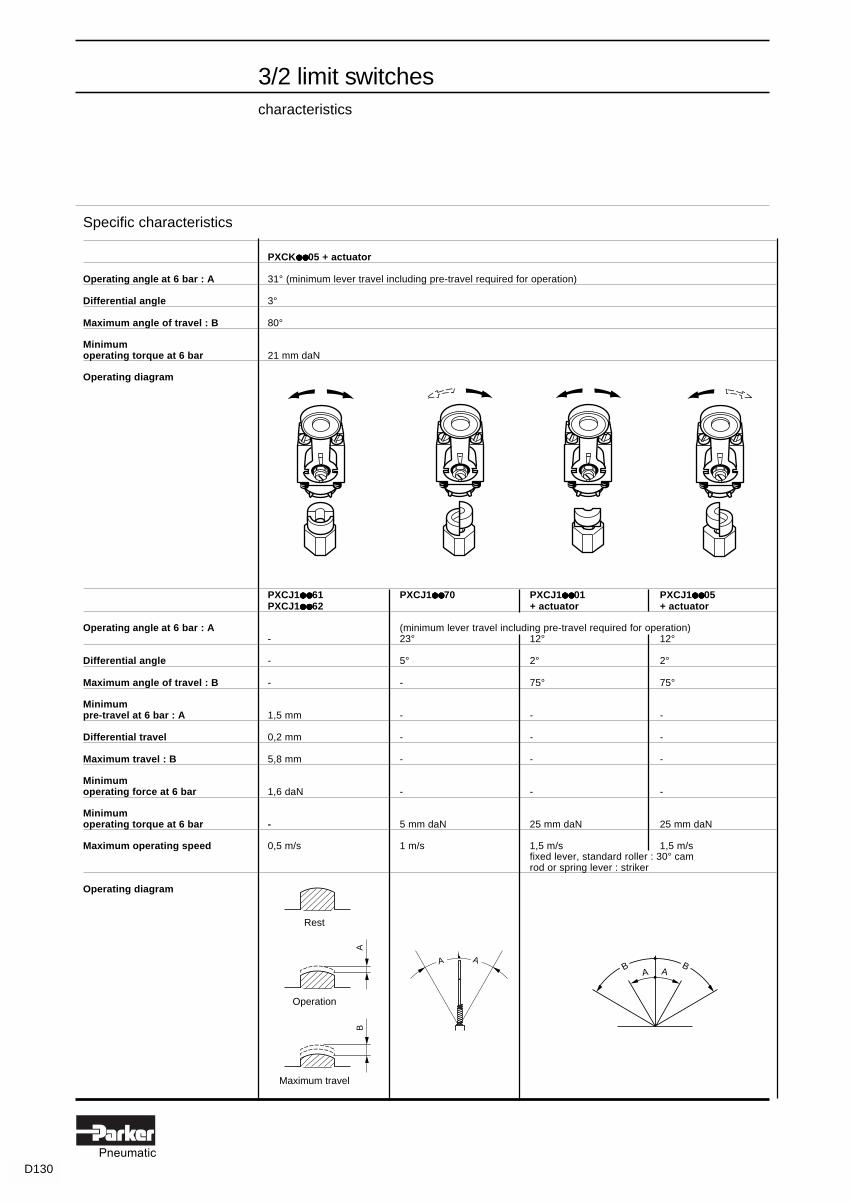
D130Pneumatic
3/2 limit switchescharacteristics
AB
A AB BA A
Specific characteristics
PXCK●●●●●●●●●● 05 + actuator
Operating angle at 6 bar : A 31° (minimum lever travel including pre-travel required for operation)
Differential angle 3°
Maximum angle of travel : B 80°
Minimumoperating torque at 6 bar 21 mm daN
Operating diagram
PXCJ1●●●●●●●●●● 61 PXCJ1●●●●●●●●●● 70 PXCJ1●●●●●●●●●● 01 PXCJ1●●●●●●●●●● 05PXCJ1●●●●●●●●●● 62 + actuator + actuator
Operating angle at 6 bar : A (minimum lever travel including pre-travel required for operation)- 23° 12° 12°
Differential angle - 5° 2° 2°
Maximum angle of travel : B - - 75° 75°
Minimumpre-travel at 6 bar : A 1,5 mm - - -
Differential travel 0,2 mm - - -
Maximum travel : B 5,8 mm - - -
Minimumoperating force at 6 bar 1,6 daN - - -
Minimumoperating torque at 6 bar - 5 mm daN 25 mm daN 25 mm daN
Maximum operating speed 0,5 m/s 1 m/s 1,5 m/s 1,5 m/sfixed lever, standard roller : 30° camrod or spring lever : striker
Operating diagram
Rest
Operation
Maximum travel

D131Pneumatic
3/2 limit switches ‘K series”dimensions
With plunger heads
Ø = 2 holes Ø 5,2
With rotary heads and operating levers
Pneumatic switch bodies
PXCK21101,PXCK22101 PXCK21102, PXCK22102 PXCK21121, PXCK22121 PXCK21106, PXCK22106
PXCK21110531, PXCK2210531 PXCK2110541, PXCK2210541
PXCK211, PXCK221
ZCKY55 ZCKY54
(1) Ø 3 3(2) 11 to 115 11 to 115(3) 53 to 158 53 to 158
ZCKY54, ZCKY55 ZCKY81 ZCKY91
Ø = 2 holes Ø 5,2
With rotary heads and operating levers
52
Ø320
0
157
16
94
20
Ø
Ø13Ø10
58,5
1510
74
20
Ø 71,5
15
112,
5
8
20
Ø
77
Ø20
48,5
201
Ø2
165,
5
20
Ø
16
135
91,5
52
Ø8
20
Ø
60
120
6 38
54
84,5
41
Ø22
20
Ø
58
6 4452
72,9
to 1
27,4
29,5
to 8
4
Ø19
29,5
10 2XØ5,2
19,5
20 ==
28
19,5
10
9
15,5
22
29,5
28
63,5
56
48
(1)
(3)
(2)
19

D132Pneumatic
3/2 limit switches ‘J series”dimensions
With plunger heads
With rotary heads and operating levers
Pneumatic switch bodies
PXCJ111, PXCJ121
ZC2JY81 ZC2JY91 ZC2JY41
PXCJ11161, PXCJ12161 PXCJ11162, PXCJ12162 PXCJ11170, PXCJ12170
PXCJ1110111, J1210111, J1110511, J1210511 PXCJ1110131, J1210131, J1110531, J1210531 PXCJ1110151, J1210151, J1110551, J1210551
With rotary heads and operating levers
108
67
5
41 to 69
65
44
Ø22
110
to 1
50 69 to
109
39 to 71
65
46 to
86
Ø22
5
189
max
.
148
max
.
54 to 66
65
125
max
.
3
38
30
12
19
29,5
48
38
= 29 to 30 =
1912
29,5
7
38
11
13
24
4XØ5,2
19,5
88
Ø12
47
4
100
19,5
59
Ø12
194
19,5
153
Ø2
128
54 to 60
65
105Ø8
200
54 to 60
65
177
Ø3
69 to
109
35 to 76
65
46 to
86
5
Ø22
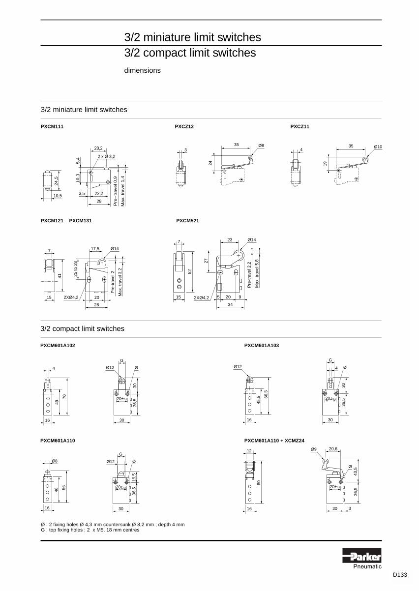
D133Pneumatic
3/2 miniature limit switches3/2 compact limit switchesdimensions
3/2 miniature limit switches
PXCM111 PXCZ12 PXCZ11
PXCM121 – PXCM131 PXCM521
15
7
41
17,5 Ø14
25 to
28
20
28
Pre
-tra
vel 2
Max
. tra
vel 3
,2
2XØ4,2
10,5
24
,5
22,23,5
29
20,2
2 x Ø 3,2
10
,35
,4
Pre
--tr
ave
l 0,9
Ma
x. t
rave
l 1,4
353
Ø8
24
354
Ø10
19
15
7
52
23 Ø14
27
20
34
Pre
-tra
vel 2
,2
Max
. tra
vel 5
,8
2XØ4,2 5 9
3/2 compact limit switches
PXCM601A102 PXCM601A103
PXCM601A110 PXCM601A110 + XCMZ24
20±0,1
36,5
30
G
30
ØØ124
70
49
16
20±0,1
36,5
30
G
19,5
ØØ12Ø8
5646
16
12
80
16
66,5
45,5
16
Ø12
20±0,1
36,5
30
20,6
43,5
Ø
Ø9
3
4
20±0,1
36,5
30
G
30
Ø
Ø : 2 fixing holes Ø 4,3 mm countersunk Ø 8,2 mm ; depth 4 mmG : top fixing holes : 2 x M5, 18 mm centres

D134Pneumatic
= At the time of printing, available on indent only.
Back pressure sensorsfor cylinder mounting
PWSP111 PWSM1012 PWSE101
PWSC●●●●●●●●●●●●●●●●●●●●
Characteristics :page D142Dimensions :page D155
PWSB199
PPRW01
&P
S
Operatingthreshold
Time
black(BK)
blue(BU)
brown(BN)
black(BK)
blue(BU)
Sensorlocking clip
Ø 4 mminstant connections
☞
...
...
Circuitpressure
Driving pressure A
Exhaust backpressure B
end of stroke
Allen key
...
P/12
Valve changeover
When ordering : 1 lot of 50 locking clips for banjo sockets,please state the exact reference. Example : 1PPRW01
brown(BN)
Plug-in back pressure sensors with 3 types of output
For use with banjo socket
Sensing Output Connections Output Reference Weightfunction function characteristics kg
Exhaust Pneumatic Tube NNP switch valve PWSP111 0,085back pressure instant flow rate at 6 bardecay Ø 4 mm 90 l/mn ANR
Electrical 3 wires C/O contact PWSM1012 0,080~ Ie = 3 A 0,5 mm2 12 to 230 V~ / 10 VA (1)
length 2 m 12 to 48 V / 5 W (1)
Electronic 3 wires PNP type N/C PWSE101 0,0700,1 mm2 10 / 30 V (2)length 2 m 75 mA N/O PWSE111 0,070
Banjos sockets for plug-in sensors
With sensor locking clip
Male thread for Female Tightening by Reference Weightcylinder port thread kgM5 M5 8 mm flat spanner PWSB155 0,0351/8" 1/8" 5 mm Allen key PWSB188 0,0401/4" 1/4" 8 mm Allen key PWSB199 0,0453/8" 3/8" 10 mm Allen key PWSB133 0,0701/2" 1/2" 12 mm Allen key PWSB122 0,105
Spare parts for back pressure sensor banjo socketsDescription Base Reference Weight
component kg1 lot of 50 locking clipsfor plug-in sensors PWSB●●● PPRW01 0,064
Monobloc version with pneumatic output
with Ø 4 mm instant connection on output ports
Symbol Thread size for Thread size for Reference Weightcylinder port supply port kg
M5 M5 PWSC1145 0,095
1/8" 1/8" PWSC4148 0,110
1/4" 1/4" PWSC1149 0,100
3/8" 3/8" PWSC4143 0,165
1/2" 1/2" PWSC1142 0,145
(1) Suitable for low currents : 250 V ~ / 4 mA ; 24 V / 10 mA(2) Including ripple
Sensing principle, assembly and connection of back pressure sensors
Sensing operation Assembly and connection
D138

D135Pneumatic
= At the time of printing, available on indent only.
Bleed sensors
For use with PRFA12 relay
Actuation Connection Reference Weightkg
Direct acting Ø 4 mm instant PXFA111 0,030
M5 PXFA115 0,030
Ball roller Ø 4 mm instant PXFA121 0,035
M5 PXFA125 0,035
Cat's whiskers Ø 4 mm instant PXFA131 0,035
M5 PXFA135 0,035
Bleed sensor relay
Symbol Utilisation Reference Weightkg
Provides a supply PRFA12 0,070to a bleed sensorand generates apneumatic signalequal to its supplypressure whenthe bleed sensoroperates.
Utilisation - connection
Bleed sensors make it possible to sense very low actuating forces or small movements and are very compact. Theyare easy to install and connect as they only require a single tube. However, the length of the interconnecting tube mustremain short if quick response times are required.
Bleed sensors
PXFA111 PXFA121 PXFA131
PRFA12
Characteristics :pages D142Dimensions :page D155
P
S
P
S
P
S
Bleed sensorrelay
Bleed sensorrelay
Bleed sensorrelay
Directacting
a
S
Cat'swhisker
Ballroller
D139

D136Pneumatic
= At the time of printing, available on indent only.
PRDA12
PXDA11●●●●●
Fluidic proximity sensors
Characteristics :page D142Dimensions :page D155
Fluidic proximity sensors
Utilisation Sensing Fixing Connections Reference Weightdistance Ø kg
Certain applications 2 to 5 mm M12 x 1 Ø 4 mm PXDA111 0,060sometimes require instantdetection withoutphysical contact, parti-culary where the objectto be detected is fragileor soft. The technique M5 PXDA115 0,340of detection by fluidicproximity sensorprovides the idealsolution to this need.
Amplifier relay
Supplied with 4 port subbases
Symbol Utilisation Connections Reference Weightkg
This relay Ø 4 mm PRDA12 0,175amplifies the instantvery low pressuresignal coming froma fluidic proximitysensor to industrialpressure level. Body: PRDA10With manual Sub-base: PZUB12control.
Pressure regulator with 0 to 4 bar gauge
With blue adjusting knob
Symbol Characteristics Connections Reference Weightkg
- Flow : 480 l/mn ANR 1/4 BSP P3A-RA12BYP 0,100 at 2 bar- Maximum primary pressure : 10 bar- Secondary pressure : 0 to 2 bar- Gauge : 0 to 4 bar P3D-KAB1ALN 0,050
Fixing bracket P3A-KA00MRN 0,030
a
S
Pp
P2DR19N2
D140

D137Pneumatic
Fluidic proximity sensorsconnection and utilisation
Connection and utilisation diagrams
The fluidic proximity sensor is designed to operate in conjunction with a pressure regulator B1562BY and an amplifierrelay PRDA12.
The pressure regulator ensures the constant air supply p to the sensor and amplifier relay.
Supply p between 100 and 300 mbar depends on the required sensing distance d and the distance L between sensorand relay.
Supply p is fed to an annular bleed which is reflected when the object to be sensed is present, producing output signala (0,5 to 3 mbar) which is amplified by the relay PRDA12 to a signal S of between 3 and 6 bar.
d = 5 mmd = 4 mm d = 3 mm
d = 2
mm
mbarsupply pressure
0
100
200
300
1 m 2 m 3 m
L
p
L = sensor - relay distance
p
REST STATE
Movingobject
P
S
PRD-A12L
a
p
PXD-A11
d
PZD-R219N2
pa
d
Sensingdistance
OPERATING STATE
Movingobject
object
D141

D138Pneumatic
Sensorscharacteristics
General characteristics
PWSM1012 PWSE1●●●●● 1 PWSP111 PWSC●●●●●●●●●●●●●●●●●●●●
Operating pressure 0 to 10 bar 0 to 10 bar 0 to 10 bar 0 to 10 bar
Permissible fluids air or neutral gas 50 µm filtration, lubricated or not
Operating temperature - 15° to + 60° C - 15° to + 60° C - 15° to + 60° C - 15° C to + 70° C
Storage temperature - 40° to + 70° C - 40° to + 70° C - 40° to + 70° C - 20° C to + 70° C
Mechanical life (number ofoperations) with dry air at 6 barand 20° C - frequency 1 Hz 10 million 10 million 10 million 10 million
Maximumoperating frequency 10 Hz 10 Hz 10 Hz 1 Hz
Vibration resistance conforming to section 19-2 of Bureau Veritas regulations
Degree of protection IP 40 IP 67 IP 50 IP 50
Materials :- body thermoplastic thermoplastic thermoplastic zinc alloy +- mounting screw brass (on PWS-B banjo) brass (on PWS-B banjo) brass (on PWS-B banjo) thermoplastic
Maximum connecting torque M5 = 1Nm ; 1/8" = 8 Nm ; 1/4" = 12 Nm ; 3/8" = 30 Nm ; 1/2" = 35 Nmon PWS-B banjo on PWS-B banjo on PWS-B banjo
Connections M5 to 1/2" M5 to 1/2" M5 to 1/2" M5 to 1/2"
Pilot pressure 1 bar 0,7 bar 4,4 bar 1,6 bar ± 0,2
Depilot pressure 0,6 bar 0,5 bar 0,4 bar 0,3 barC/O contact PNP contact pneumatic pneumatic
Output signal characteristics 2,5 A / 250 V ~ N/O or N/C flow at 6 bar flow at 6 bar5 W / 48 V ... 10-30 V ... / 75 mA 90 l/mn ANR 90 l/mn ANR
instant instantConnections connections connections
- - for Ø 4 mm tube for Ø 4 mm tube
PXFA11●●●●● PXFA12●●●●● PXFA13●●●●● PXDA11●●●●●
Minimumpre-travel at 6 bar - 1 mm - -
Maximum travel - 2,8 mm - -
Minimumoperating force at 6 bar - 0,3 daN - -
Minimum (centre of operator)operating torque at 6 bar - - 1,25 mm daN -
Sensing distance direct direct direct 1 to 5 mm
Sensing angle - - 10° -
D142

D139Pneumatic
= At the time of printing, available on indent only.
Spring return pushbuttons
Colour Type of Reference Weightswitching (1) Complete kg
Black NNP PXBB1011BA2 0,090
NNP + NP PXBB1121BA2 0,125
Green NNP PXBB1011BA3 0,090
Red NNP PXBB1011BA4 0,090
Mushroom head pushbuttons
Ø 40 mm
Function and colour Type of Reference Weightswitching (1) Complete kg
Spring return NNP PXBB1011BC2 0,105Black
Push-pull NNP PXBB1011BT4 0,135Red
NP PXBB1021BT4 0,135
Selector switches
Function and colour Type of Reference Weightswitching (1) Complete kg
2 stay put positions NNP PXBB1011BD2 0,100with standard handle NNP + NNP PXBB1111BD2 0,135Black NNP + NP PXBB1121BD2 0,135
3 stay put positions NNP + NNP PXBB1111BD3 0,135with standard handle NNP + NP PXBB1121BD3 0,135Black3 positions, spring return to centrewith long handle NNP + NNP PXBB1111BJ5 0,140Black NP + NP PXBB1221BJ5 0,140
(1) NNP : normally non passing.
NP : normally passing.
NNP + NNP : double switch body, both normally non passing.
NNP + NP : normally non passing and normally passing.
NP + NP : both normally passing
Variable composition Ø 22 mm control unitswith 3/2 switch valvesflow 50 l/mn ANRwith Ø 4 mm straight or swivel instant connections
PXBB1121BD2
PXBB1021BT4
PXBB1011BA2
Characteristics :page D154Dimensions :page D156
Components
PXBB1011ZB2BA2
PXBB1011PXBB1921ZB2BA2
PXBB1011ZB2BA3
PXBB1011ZB2BA4
Components
PXBB1011ZB2BC2
PXBB1011ZB2BT4
PXBB1021ZB2BT4
Components
"A"+"C""A"+"C"+"G""A"+"C" +"F"
"A"+"D"+"G""A"+"D" +"F"
"A"+"E"+"G""B"+"E" +"F"
"A" = PXBB1011"B" = PXBB1021"C" = ZB2BD2"D" = ZB2BD3"E" = ZB2BJ5"F" = PXBB1921"G" = PXBB1911
D143
OBS
OLE
TE P
RO
DU
CTS
FO
R C
UR
REN
T EQ
UIV
ALEN
T VA
LVES
PLE
ASE
REF
ER T
O C
ATAL
OG
UE
PD0C
0001
8GB0
1-EV
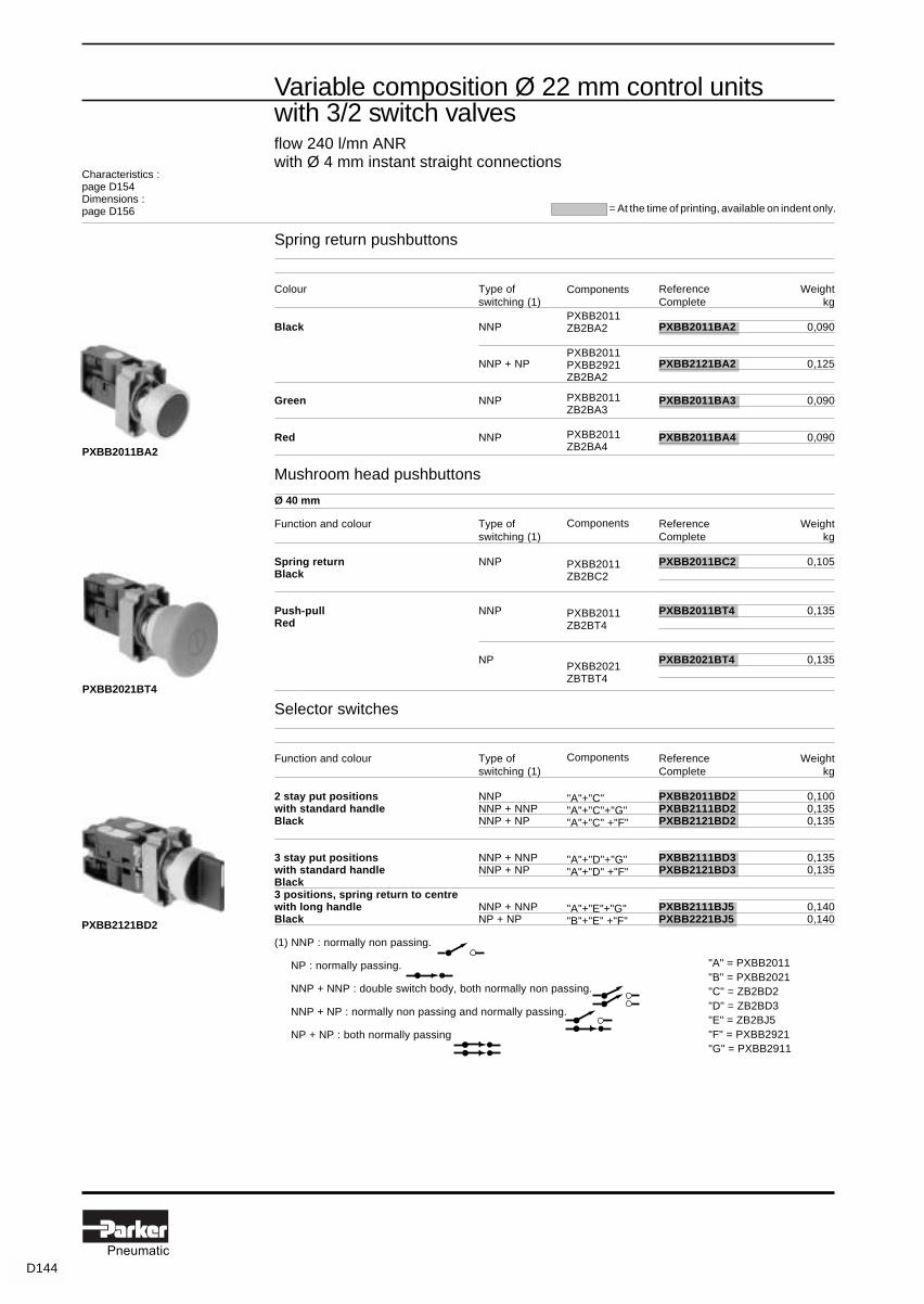
D140Pneumatic
Variable composition Ø 22 mm control unitswith 3/2 switch valvesflow 240 l/mn ANRwith Ø 4 mm instant straight connections
PXBB2011BA2
PXBB2021BT4
PXBB2121BD2
Spring return pushbuttons
Colour Type of Reference Weightswitching (1) Complete kg
Black NNP PXBB2011BA2 0,090
NNP + NP PXBB2121BA2 0,125
Green NNP PXBB2011BA3 0,090
Red NNP PXBB2011BA4 0,090
Mushroom head pushbuttons
Ø 40 mm
Function and colour Type of Reference Weightswitching (1) Complete kg
Spring return NNP PXBB2011BC2 0,105Black
Push-pull NNP PXBB2011BT4 0,135Red
NP PXBB2021BT4 0,135
Selector switches
Function and colour Type of Reference Weightswitching (1) Complete kg
2 stay put positions NNP PXBB2011BD2 0,100with standard handle NNP + NNP PXBB2111BD2 0,135Black NNP + NP PXBB2121BD2 0,135
3 stay put positions NNP + NNP PXBB2111BD3 0,135with standard handle NNP + NP PXBB2121BD3 0,135Black3 positions, spring return to centrewith long handle NNP + NNP PXBB2111BJ5 0,140Black NP + NP PXBB2221BJ5 0,140
(1) NNP : normally non passing.
NP : normally passing.
NNP + NNP : double switch body, both normally non passing.
NNP + NP : normally non passing and normally passing.
NP + NP : both normally passing
Characteristics :page D154Dimensions :page D156 = At the time of printing, available on indent only.
Components
PXBB2011ZB2BA2
PXBB2011PXBB2921ZB2BA2
PXBB2011ZB2BA3
PXBB2011ZB2BA4
Components
PXBB2011ZB2BC2
PXBB2011ZB2BT4
PXBB2021ZBTBT4
Components
"A"+"C""A"+"C"+"G""A"+"C" +"F"
"A"+"D"+"G""A"+"D" +"F"
"A"+"E"+"G""B"+"E" +"F"
"A" = PXBB2011"B" = PXBB2021"C" = ZB2BD2"D" = ZB2BD3"E" = ZB2BJ5"F" = PXBB2921"G" = PXBB2911
D144

D141Pneumatic
= At the time of printing, available on indent only.
Variable composition 3/2 switch bodiesfor use with Ø 22 mm operating headsflow 50 l/mn ANRwith Ø 4 mm straight or swivel instant connections
ZB2BE101 ● ● ● ● ● BE102 ●●●●● BZ009
PXBB1911 PXBB1922
PXBB1011 PXBB1021
Switch bodies with operating head mounting
For use with ZB2B operating heads (see pages D147and D148)
Connections Type of switching Reference Weightkg
Ø 4 mm instant Normally non passing (NNP) PXBB1011 0,045straight connections
Normally passing (NP) PXBB1021 0,045
Additional switch valves
For use with PBX bodies with operating head mounting
Connections Type of switching Reference Weightkg
Ø 4 mm instant Normally non passing (NNP) PXBB1911 0,020straight connections
Normally passing (NP) PXBB1921 0,020
Ø 4 mm instant Normally non passing (NNP) PXBB1912 0,025swivel connections
Normally passing (NP) PXBB1922 0,025
Electrical contact blocks
Connections Type of contact Reference Massekg
When combined with pneumatic units,these contact blocks enable data with Normally open (N/O) ZB2BE101 0,015two different kinds of power to beprovided from a single control unit.Can be mounted with both types of Normally closed (N/C) ZB2BE102 0,015valves PXBB1●●● and PXBB2●●●
Mounting block for valves and operating heads : ZB2BZ009 0,025to make up a complete pushbutton with one or twoswitching elements with Ø 4 mm instant swivelconnections, use this mounting block and select theoperating heads on pages D147 and D148.
D145
OBS
OLE
TE P
RO
DU
CTS
FO
R C
UR
REN
T EQ
UIV
ALEN
T VA
LVES
PLE
ASE
REF
ER T
O C
ATAL
OG
UE
PD0C
0001
8GB0
1-EV

D142Pneumatic
= At the time of printing, available on indent only.
Variable composition 3/2 switch bodiesfor use with Ø 22 mm operating headsflow 240 l/mn ANRwith Ø 4 mm straight or swivel instant connections
PXBB2911 PXBB2922
ZB2BE101 ● ● ● ● ● BE102 ●●●●● BZ009
PXBB2011 PXBB2021
Switch bodies with operating head mounting
For use with ZB2B operating heads (see pages D147and D148)
Connections Type of switching Reference Weightkg
Ø 4 mm instant Normally non passing (NNP) PXBB2011 0,060straight connections
Normally passing (NP) PXBB2021 0,060
Additional switch valves
For use with PBX bodies with operating head mounting
Connections Type of switching Reference Weightkg
Ø 4 mm instant Normally non passing (NNP) PXBB2911 0,035straight connections
Normally passing (NP) PXBB2921 0,035
Ø 4 mm instant Normally non passing (NNP) PXBB2912 0,040swivel connections
Normally passing (NP) PXBB1922 0,040
Electrical contact blocks
Connections Type of contact Reference Massekg
When combined with pneumatic units,these contact blocks enable data with Normally open (N/O) ZB2BE101 0,015two different kinds of power to beprovided from a single control unitCan be mounted with both types of Normally closed (N/C) ZB2BE102 0,015valves PXBB1●●● and PXBB2●●●
Mounting block for valves and operating heads : ZB2BZ009 0,025to make up a complete pushbutton with one or twoswitching elements with Ø 4 mm instant swivelconnections, use this mounting block and select theoperating heads on pages D147 and D148.
D146

D143Pneumatic
= At the time of printing, available on indent only.
Ø 22 mm operating headsfor use with PXB-B switch bodies
Spring return pushbuttons
Description Colour Reference Weightkg
Flush Black ZB2BA2 0,030Green ZB2BA3 0,030Red ZB2BA4 0,030
Projecting Black ZB2BL2 0,030Green ZB2BL3 0,030Red ZB2BL4 0,030
Flush booted Black ZB2BP2 0,025Green ZB2BP3 0,025Red ZB2BP4 0,025
Mushroom head pushbuttons
Description Function Colour Reference Weightkg
Ø 40 mm Spring return Black ZB2BC2 0,045mushroom head Green ZB2BC3 0,045
Red ZB2BC4 0,045Latching Black ZB2BT2 0,075push-pull Red ZB2BT4 0,075
Ø 60 mm Spring return Black ZB2BR2 0,055mushroom head Red ZB2BR4 0,055
Latching Black ZB2BX2 0,080push-pull Red ZB2BX4 0,080
Description Function Colour Reference Weightkg
Ø 40 mm Latching Red ZB2BS54 0,055mushroom head Turn to release
Latching Red ZB2BS14 0,090Release by Ronis key N° 455
Ø 60 mm Latching Red ZB2BS64 0,065mushroom head Turn to release
Latching Red ZB2BS24 0,120Release by Ronis key N° 455
ZB2BC4 ZB2BR2
ZB2BA2 ZB2BL3
ZB2BS24
D147

D144Pneumatic
= At the time of printing, available on indent only.
Selector switches
Description Function Reference Weightkg
Standard 2 positions stay put ZB2BD2 0,040black handle
3 positions stay put ZB2BD3 0,0402 spring return to centre ZB2BD5 0,040
Long 2 positions stay put ZB2BJ2 0,045black handle 3 positions stay put ZB2BJ3 0,045
spring return to centre ZB2BJ5 0,0451 spring return ZB2BJ7 0,045from left to centre
Description Function Key withdrawal Reference Weightkg
Key operated 2 stay put positions Left ZB2BG2 0,070(Ronis N° 455) Left and right ZB2BG4 0,070
3 stay put positions Centre ZB2BG3 0,070Left and right ZB2BG5 0,070
3 positions Centre ZB2BG7 0,070spring return to centre
Ø 22 mm operating headsfor use with PXB-B switch bodies
ZB2BG7
ZB2BD3 ZB2BJ3
D148

D145Pneumatic
= At the time of printing, available on indent only.
PXBDD512
PXBDD104
Characteristics :page D154Dimensions :page D156
21
3 4 5678
9101112
1 2 3 4 5 6 7 8 9 10 11 12
1 2 3 4
2
1 3
4
PXBDD508
2
1
3 4
56
78
1 2 3 4 5 6 7 8
Ø 22 mm rotary switches with switch valves 3/2flow 50 l/mn ANRwith Ø 4 mm instant straight connections
4 positions - 4 switch valves 3/2 (1)
Without mechanical stop
Symbol Operating head Type of Reference Weightswitching (2) kg
Black handle with NNP PXBDD104 0,21064 x 64 mm legend platered or black background
8 positions - 8 switch valves 3/2 (1)
Without mechanical stop
Symbol Operating head Type of Reference Weightswitching (2) kg
Black handle with NNP PXBDD508 0,31064 x 64 mm legend platered or black background
12 positions - 12 switch valves 3/2 (1)
Without mechanical stop
Symbol Operating head Type of Reference Weightswitching (2) kg
Black handle with NNP PXBDD512 0,45064 x 64 mm legend platered or black background
(1) These rotary switches operate in either direction.They are fitted with switch valves type PXBB1921.Rotation of the operating knob inverts the switch valve pressure signals :Example of operation : rotation from position 1 to position 2 :- switch valve n° 1 changes state from NP to NNP- switch valve n° 2 changes state from NNP to NP
(2) NNP : normally non passing
D149

D146Pneumatic
= At the time of printing, available on indent only.
2 direction - 2 switch valves 3/2
Symbol Operating Function Type of Reference Weighthead switching (1) kg
Chrome 1 stay put NNP PXBGA8211 0,300plated lever positionwith protective in eachbellows. direction40 x 64 mmlegend platered or black 1 position NNP PXB-GA8221 0,300background in each
direction withspring return
4 direction - 4 switch valves 3/2
Symbol Operating Function Type of Reference Weighthead switching (1) kg
Chrome 1 stay put NNP PXBGA4211 0,330plated lever positionwith protective in eachbellows. direction40 x 64 mmlegend platered or black 1 position NNP PXBGA8421 0,330background in each
direction withspring return
(1) NNP : normally non passing.
PXBGA8411
PXBGA8211
D
BC
A
A B
Characteristics :page D154Dimensions :page d156
Ø 22 mm joystick controllers with switch valve 3/2flow 50 l/mn ANRwith Ø 4 mm instant straight connections
D150

D147Pneumatic
= At the time of printing, available on indent only.
Ø 22 mm and Ø 30 mm visual indicatorswith Ø 4 mm instant straight connections
PXVM131
PXVF131
Ø 22 mm visual indicators
Black plastic bezel
Symbol Colour (1) In the actuated state Weight In the unactuated state WeightReference kg Reference kg
Green PXVF131 0,080 PXVF1213 0,080
Red PXVF141 0,080 PXVF1214 0,080
Yellow PXVF151 0,080 PXVF1215 0,080
Blue PXVF161 0,080 PXVF1216 0,080
White PXVF111 0,080 PXVF1211 0,080
Ø 22 mm visual indicators
Chrome plated bezel
Symbol Colour (1) In the actuated state WeightReference kg
Green PXVM131 0,085
Red PXVM141 0,085
Yellow PXVM151 0,085
(1) The pneumatic indicators are black in one position and coloured in the other.The coloured position corresponds either to the presence of pressure (actuated state) or the absence of pressure(unactuated state). For two different colours on the same indicator, please consult your local Sales Office.
Characteristics :page D154Dimensions :pages D156
D151

D148Pneumatic
= At the time of printing, available on indent only.
Two-hand control units (1)modules and complete unitsspare parts
Control module only
Symbol Connections Reference Weightkg
Instant PXPA11 0,250connectionsfor tubeØ 4 mm
Complete units
Comprising a polyester enclosure equipped with two mushroom head pushbuttons
Symbol Connections Number of Reference Weightcontrol modules kg
Instant One PXPC111 1,000connectionsfor tube Ø 4 mm
Instant Two (2) PXPD121 1,000connectionsfor tube Ø 4 mm
Complete units
Comprising a metal enclosure equipped with two mushroom head pushbuttons
Symbol Number of Reference Weightcontrol modules kg
One PXPB111 2,800
Two (2) PXPE121 3,200
"European type" metal enclosure equipped with two Ø 60 pushbuttons with protective guards
Symbol Connections Number of Reference Weightcontrol modules kg
Instant One PXPS111 4,200connectionsfor tubeØ 6 for supplyØ 4 for output
Instant Two (2) PXPS121 4,400connectionsfor tubeØ 6 for supplyØ 4 for output
Spare parts for two-hand control units
Composition Base Reference Weightcomponent kg
1 guard for two-hand control PXPC111 PPRL15 0,050PXPD121
(1) These units are indispensable for ensuring that both the operator's hands are occupied for reasons of safety. Bothpushbuttons must be operated simultaneously to produce an output signal.Application example : presses
(2) Conforming to French standard NF E09-036 "Pneumatic synchronous two-hand controls"..
Characteristics :page D154Dimensions :page D157
a
b
P
S
PXPA11
SP
T
T
T
TP S
&
SP
T
T
T
TP S
&
SP
T
T
T
TP S
&
PXPB111
PPRL15
PXPS111
PXPC111
D152

D149Pneumatic
= At the time of printing, available on indent only.
Foot switches (2)flow 50 l/mn ANRwith Ø 4 mm instant straight connections
Foot switches with protective guard and interlock mechanism
Type of pedal Function Type of Reference Weightswitching (1) kg
Metal Spring return NNP PXPEM510 2,530
High resistance protective guard.Return of the pedal to the unoperated state ensuredby a safety spring independent of the switchingelement.With interlock mechanism to prevent accidentaloperation by a falling object.
Foot switches without protective guard
Type of pedal Function Type of Reference Weightswitching (1) kg
Plastic Spring return NNP PXPEA110 0,275
Type of pedal Function Type of Reference Weightswitching (1) kg
Metal Spring return NNP PXPEM110 1,200
Latching NNP PXPEM410 1,200When the pedal is depressed, a pneumatic signalis given. When released, the signal is stored by thelatching device. Breaking the pneumatic signal iscarried out by pressing the lever.
(1) NNP : normally non passing.
(2) These foot switches are fitted with a switch valve 3/2, type PXBB1921.additional switch valves makes it possible to obtain different combinations (NNP + NP, NNP + NNP, ...).See page D154.
PXPEM510
PXPEA110
PXPEM410
Characteristics :page D154Dimensions :page D157
D153

D150Pneumatic
General characteristics
Ø 22 pushbuttons Ø 30 Ø 22 and Ø 30 Two-hand Foot Selector Joystickflow 50 l/mn flow 240 l/mn pushbuttons visual indicators controls switches switches controllersPXBB1●●●●● PXBB2●●●●● PXBM PXV●●●●● PXP●●●●● PXPE PXBDD PXBGA
Operating pressure 1 to 9 bar 3 to 8 bar 3 to 8 bar 1 to 8 bar 3 to 8 bar 1 to 9 bar 1 to 9 bar 1 to 9 bar
Permissible fluids air or neutral gas 50 µm, lubricated or not
Flow (in l/mn ANR) at 6 bar 50 240 210 - 200 50 50 50
Nominal bore 1,5 3 3 - 2,5 1,5 1,5 1,5
Operating temperature - 15° C to + 60° C (below + 5° C, an air dryer is required)
Storage temperature - 40° to + 70° C
Mechanical life (number ofoperations) at 6 bar with dry airand at 20° C - frequency 1 Hz 1 million operations except mushroom head = 300.000 operations
Vibration resistance conforming to section 19-2 of Bureau Veritas regulations
Protective treatment All climates (TC)
- body : plasticMaterials - operating head : zinc alloy and plastic
Connections Ø 4 mm instant
Operating positions All
Separate components (head + body) yes no
Specific characteristics
Spring return pushbuttons PXBB and PXBM
Minimumpre-travel at 6 bar : A 3 mm 3,2 mm 6,3 mm - - - - -
Maximum travel : B 4,8 mm 4,8 mm 7 mm - - - - -
Minimumoperating force at 6 bar 1,3 daN 1,3 daN 2 daN - - - - -
Spring return mushroom head pushbuttons PXBB and PXBM
Minimumpre-travel at 6 bar : A 3 mm 3,2 mm 6,3 mm - - - - -
Maximum travel : B 4,8 mm 4,8 mm 7 mm - - - - -
Minimumoperating force at 6 bar 1,8 daN 1,3 daN 2 daN - - - - -
Latching mushroom head pushbuttons PXBB and PXBM
Minimumpre-travel at 6 bar : A 3,5 mm 3,5 mm 5,3 mm - - - - -
Maximum travel : B 4,8 mm 4,8 mm 6,5 mm - - - - -
Minimumoperating force at 6 bar 5 daN 5 daN 4,5 daN - - - - -
Foot switches PXPE
Minimum operating force at 6 bar 4,2 daN
Joystick controllers PXBGA
Operating angle 18°
Operating torque 42 mm daN
Man / Machine dialoguecharacteristics
Man / Machine dialoguecharacteristics
D154
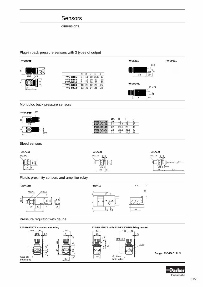
D151Pneumatic
Sensorsdimensions
18 X 24
2m32
2m32
Ø16
H
K
C
B
LB/2
18,5
24,5
Plug-in back pressure sensors with 3 types of output
PWSB1●●●●●●●●●● PWSE111 PWSP111
PWSM1012
Monobloc back pressure sensors
PWSC●●●●●●●●●●●●●●●
Bleed sensors
PXFA111 PXFA121 PXFA131
Fluidic proximity sensors and amplifier relay
PXDA11●●●●● PRDA12
Pressure regulator with gauge
P3A-RA12BYP standard mounting P3A-RA12BYP with P3A-KA00MRN fixing bracket
Gauge: P3D-KAB1ALN
38
43M12X1
25
==
12,5
30
56
18
17
2XØ3,2
15
4014
14
H
LB/2
ØA
Ø4
B
C B K H LPWS-B155 8 11 10 16,5 17PWS-B188 5 16 10 20 20
PWS-B199 8 21 10 20 22PWS-B133 10 28 12 22 25PWS-B122 12 33 14 26 26
ØA B H LPWS-C1145 19 11 16 42PWS-C4148 22 16,5 29 40PWS-C1149 22 23,5 26 43PWS-C4143 22 23,5 36,5 43PWS-C1142 22 32 29,5 48
�����������
1,5
G1/8 onboth sides
52
540
40
12
32
5
~55 31
M30x1,5
G 1/4"
22
20
M12X1
Ø17
838
96
Ø1,5
M12X1
12438Ø17
96
Ø1,5
35
~55 31
1,5Ø30
40
48
5
35
G1/8 onboth sides
10
550
5
4640
������������
M12X1
Ø17
818
D155

D152Pneumatic
Variable composition Ø 22 mm control units - flow 50 l/mn ANR and 240 l/mn ANR
PXBB1●●●●●●●●●●●●●●● PXBB2●●●●●●●●●●●●●●● PXBB19●●●●● 2 - PXBB29●●●●● 2 ZB2BE10●●●●●
with straight connections with swivel connections
Man / machine dialogueDimensions
Ø 22 mm rotary switches
PXBDD●●●●●●●●●●●●●●●●●●●●
Ø 22 mm joystick controllers
PXBGA82●●●●●●●●●● PXBGA84●●●●●●●●●●
Ø 22 mm visual indicators
PXVF1●●●●●●●●●● Maximum distance between centres
Body width 30 mm* With 2 x 4 mm tube = 10* With 2,7 x 4 mm tube = 15
58
4040
87
1515 30
60
(1)
* *
58
4040
87
1515 30
60
(1)
* *
43
1,5 to 6
40
64*
1,5 to 6
40
14
44
Ø22,2 UTE
30
Ø22,5 DIN40
43*
1,5 to 6
40
72
b1
271,5 to 6 mmØ
29
40
b14 positions 608 positions 9012 positions 120
Ø22,2 UTE
30
Ø22,5 DIN
4014
44
* In both directions * In 4 directions
(1) Ø 4 mm instant connections (1) Ø 4 mm instant connections
53 16
Ø28
1,5 to 6
D156
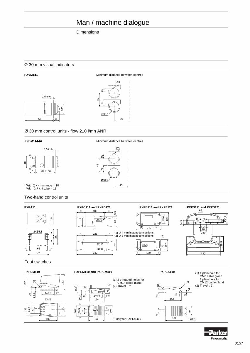
D153Pneumatic
Man / machine dialogueDimensions
Two-hand control units
PXPA11 PXPC111 and PXPD121 PXPB111 and PXPE121 PXPS111 and PXPS121
* With 2 x 4 mm tube = 10* With 2,7 x 4 tube = 15
Foot switches
PXPEM510 PXPEM110 and PXPEM410 PXPEA110
Ø 30 mm visual indicators
PXVM1●●●●● 1 Minimum distance between centres
Ø 30 mm control units - flow 210 l/mn ANR
PXBM1●●●●●●●●●●●●●●●●●●●● Minimum distance between centres
60
==
65
2XØ4,2
==
77
60
==
65
2XØ4,2
==
77
40
27146,5
(1)
13
7
29
14
,5
15
2
186
160
3XØ9
135
89,5
31
==
==
104
==
172
107
89,5
31
==
3XØ9 94
==
161
28
Ø6,4
(1)
105
22,5 8 8,5146,5
59
164
(2)
* (1)
23
54
154
(2)
11 6
(1) 1 plain hole for(1) CM8 cable gland(1) 1 plain hole for(1) CM12 cable gland(2) Travel : 6°
(1) 2 threaded holes for(1) CM14 cable gland(2) Travel : 7°
(*) only for PXPEM410
40
62 to 66*
1,5 to 6
== 226
342
85
== 180
5,5
70=
=
2xØ5
87(1)
(1)
127
240
Ø70
170
112
7225
= =
4xØ9
(1) (1) =
75
430
188,
5
136,
240
=
44,5
240
69
(1) (2)
(1) Ø 4 mm instant connections(2) Ø 6 mm instant connections
45
45
2415
Ø5
Ø30,5
45
45
2415
Ø5
Ø30,5
53 16
Ø35
1,5 to 6
D157

D154Pneumatic
BLANK

D155Pneumatic
= At the time of printing, available on indent only.
Modular sequencerwith Ø 4 mm instant swivel connectionswith pressure indicators
PSMA12
PSEA12
B
RP
A
B
A
PSDB12
B
A
B
AR
Step modules
Symbol Reference Weightkg
Pneumatic With PSMA12 0,175output display manual controlby indicator
Without PSMB12 0,170manual control
Set of head and tail modules
Symbol Reference Weightkg
Pressure supply (P) PSEA12 0,080by Ø 6 mm instantconnectionProtection by 50 µm filter
Deviation modules
Symbol Reference Weightkg
Used for PSDA12 0,050- parallel sequences- optional sequences- repeat sequences- skip step
for the remote PSDB12 0,050reinitialization ofthe last step module
Characteristics : page D169Dimensions : page D176
D159

D156Pneumatic
= At the time of printing, available on indent only.
Modular sequencerwith Ø 4 mm instant swivel connectionswith pressure indicators
PSVA12
PSBA12
Characteristics : page D169Dimensions : page D176
PSMA10
Additional step module interlock
Symbol Reference Weightkg
May be mounted PSVA12 0,045between the subbaseand the step module tointerrupt the sequenceif a sensor is found tobe faulty
Step module memory
For mounting on PSBA12 subbases
Symbol Reference Weightkg
Pneumatic With PSMA10 0,135output display manual controlby indicator
Without PSMB10 0,130manual control
Step module subbase
For mounting on PSMA10 or PSMB10 step module memory
Reference Weightkg
PSBA12 0,040
D160

D157Pneumatic
Line mounted logic elementswith Ø 4 mm instant straight connections
PLLA11
PLKA11
PZML199
Characteristics : page D169Dimensions : page D176
AND element
Symbol Reference Weightkg
PLLA11 0,065
OR element
Symbol Reference Weightkg
PLKA11 0,065
Screw and clip assembly
Sold in lots of 10
Function Reference Weightkg
Enables line mounted PZML199 0,015logic elements to bemounted on omega rail
S
ba
1
S
ba
&
D161

D158Pneumatic
Combinable logic elementswith Ø 4 mm instant swivel connectionswith pressure indicators
PLEB12
PLNB12
PLLB12 PLKB12
AND element - OR element
Symbol Function Reference Weightkg
AND With integral key for combination PLLB12 0,080and operating mode selection
OR With integral key for combination PLKB12 0,080and operating mode selection
NOT element
Symbol Reference Weightkg
With integral key for combination PLNB12 0,080and operating mode selection
Input module
Symbol Reference Weightkg
With integral key for combination, PLEB12 0,075clip for mounting on omega railand blanking plate for closinga bank of combined elements
Characteristics : page D169Dimensions : page D176
&
S
ba
S
ba
1
&
S
ba
D162

D159Pneumatic
AND element - OR element
For mounting on 3-port subbases, with output signal pressure indicator
Symbol Logic Reference Weightfunction kg
AND PLLC10 0,025
OR PLKC10 0,025
NOT element
For mounting on 3-port subbases, with input and output signal pressure indicator
Symbol Logic Reference Weightfunction kg
NOT Standard PLNC10 0,025inhibit
Threshold PLND10 0,025
YES element
For mounting on 3-port subbases, with input and output signal pressure indicator
Symbol Logic Reference Weightfunction kg
YES PLJC10 0,025regenerate
Subbase mounting logic elements
PLLC10 PLKC10
PLNC10 PLND10
PLJC10
S
a
S
a
&
&
S
a
&
S
a
S
a
1
Characteristics :pages D169 & D170Dimensions : D176
D163
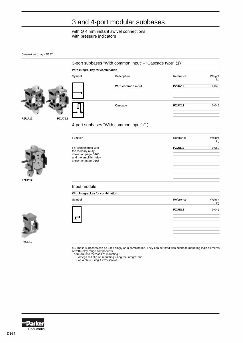
D160Pneumatic
3 and 4-port modular subbaseswith Ø 4 mm instant swivel connectionswith pressure indicators
PZUE12
PZUA12 PZUC12
PZUB12
3-port subbases "With common input" - "Cascade type" (1)
With integral key for combination
Symbol Description Reference Weightkg
With common input PZUA12 0,040
Cascade PZUC12 0,045
4-port subbases "With common input" (1)
Function Reference Weightkg
For combination with PZUB12 0,050the memory relayshown on page D165and the amplifier relayshown on page D166
Input module
With integral key for combination
Symbol Reference Weightkg
PZUE12 0,045
(1) These subbases can be used singly or in combination. They can be fitted with subbase mounting logic elementsor with relay range components.There are two methods of mounting :(1) - omega rail clip-on mounting using the integral clip,(1) - on a plate using 4 x 25 screws
Dimensions : page D177
D164

D161Pneumatic
= At the time of printing, available on indent only.
Time delay and memory relayson modular subbaseswith Ø 4 mm instant swivel connectionswith pressure indicators
PRTA10
PLMA12
PLMA10
S
YX
P
Time delay relay - complete with subbase
Mounted on 3-port "common input" modular subbase (see p. D164)
Symbol Function Timing Reference Weightrange kg
Positive 0,1 to 30 s PRTA12 0,165output
Body: PRTA10Sub-base: PZUA12
Time delay relays without subbase
For mounting on 3-port "common input" or "cascade" modular subbase (see p. D164)
Symbol Function Timing Reference Weightrange kg
Positive 0,1 to 3 s PRTE10 0,125output 0,1 to 30 s PRTA10 0,125
10 to 180 s PRTB10 0,125
Negative 0,1 to 3 s PRTF10 0,125output 0,1 to 30 s PRTC10 0,125
10 to 180 s PRTD10 0,125
Tamper proof cap LA9D901 0,030
Memory relay - complete with subbase
Mounted on 4-port modular subbase (see page D164)
Symbol Reference Weightkg
With priority With manual PLMA12 0,185reset signal control
Body: PLMA10Sub-base: PZUB12
Memory relays without subbase
For mounting on 4-port modular subbase (see page D164)
Symbol Reference Weightkg
With priority With manual PLMA10 0,135reset signal control
Without manual PLMB10 0,130control
Characteristics : pages D169 & D170Dimensions : page D177
PRTA12
S
YX
P
a
S
01t
a
S
01t
a
S
01t
D165
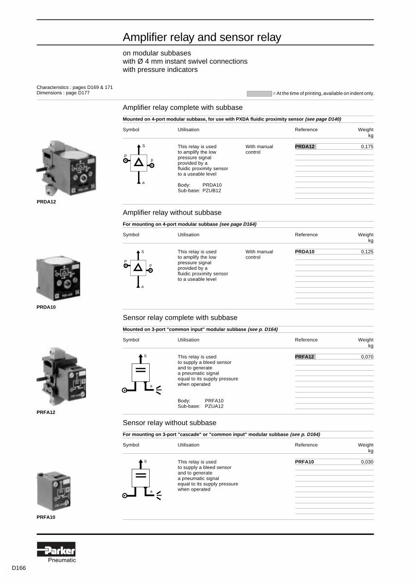
D162Pneumatic
= At the time of printing, available on indent only.
Amplifier relay and sensor relayon modular subbaseswith Ø 4 mm instant swivel connectionswith pressure indicators
PRDA10
PRDA12
PRFA12
PRFA10
a
S
Pp
a
S
Pp
Characteristics : pages D169 & 171Dimensions : page D177
S
a
S
a
Amplifier relay complete with subbase
Mounted on 4-port modular subbase, for use with PXDA fluidic proximity sensor (see page D140)
Symbol Utilisation Reference Weightkg
This relay is used With manual PRDA12 0,175to amplify the low controlpressure signalprovided by afluidic proximity sensorto a useable level
Body: PRDA10Sub-base: PZUB12
Amplifier relay without subbase
For mounting on 4-port modular subbase (see page D164)
Symbol Utilisation Reference Weightkg
This relay is used With manual PRDA10 0,125to amplify the low controlpressure signalprovided by afluidic proximity sensorto a useable level
Sensor relay complete with subbase
Mounted on 3-port "common input" modular subbase (see p. D164)
Symbol Utilisation Reference Weightkg
This relay is used PRFA12 0,070to supply a bleed sensorand to generatea pneumatic signalequal to its supply pressurewhen operated
Body: PRFA10Sub-base: PZUA12
Sensor relay without subbase
For mounting on 3-port "cascade" or "common input" modular subbase (see p. D164)
Symbol Utilisation Reference Weightkg
This relay is used PRFA10 0,030to supply a bleed sensorand to generatea pneumatic signalequal to its supply pressurewhen operated
D166

D163Pneumatic
= At the time of printing, available on indent only.
Solenoid actuatorson 3-port modular subbaseswith Ø 4 mm instant swivel connectionswith pressure indicators
PRSA121B
Complete units
For mounting on 3-port "common input modular subbase (see p. D164)
Symbol Reference Weightkg
With manual 24 V~ 50 / 60 Hz 6 VA PRSA121B 0,165control and22 x 30 mmplug-inconnector 24 V ... 5 W PRSA122B 0,165
Body: PVAF10** 115 V ~ 50 Hz 6 VA PRSA121F 0,165(see below) 120 V ~ 60 Hz
Sub-base PRSD10
230 V ~ 50 Hz 6 VA PRSA121M 0,165240 V ~ 60 Hz
Units without subbase
For mounting on 3-port "cascade" or "common input" subbase (see p. D164)
Description Reference Weightkg
Solenoid mounting base For mounting the solenoidwith coil and plunger on PRSD10 0,090manual control 3-port modular subbases
Solenoid coil (1) 24 V ... 5 W PVAF102B 0,135with plunger (1) 48 V ... 5 W PVAF102E 0,13522 x 30 mmplug-in connector 24 V~ 50 / 60 Hz 6 VA PVAF101B 0,135
48 V~ 50 / 60 Hz 6 VA PVAF101E 0,135115 V~ 50 Hz / 120 V~ 60 Hz 6 VA PVAF101F 0,135230 V~ 50 Hz 6 VA PVAF101M 0,135240 V~ 60 Hz255 V~ 50 Hz 6 VA PVAF101U 0,135
(1) Versions available for operation in explosive atmospheres. - conforming to certificate LCIE 866115X - electrical equipment conforming to harmonised European standards EN 50014 dated March 1977 (NFC 23514 dated May 1982) EN 50019 dated March 1977 (NFC 23519 dated May 1982) - referencing code EExe II T4 (consult your local Sales Office.)
Characteristics : page D169Dimensions : page D177
A B
PRSD10 PVAF10●●●●●●●●●●
D167

D164Pneumatic
= At the time of printing, available on indent only.
Pressure switcheswith Ø 4 mm instant swivel connectionswith pressure indicators
PREA12
Complete unit
Mounted on 3-port "common input" modular subbase (see p. D164)
Symbol Electrical Reference Weightcharacteristics kg
N/O contact With manual PREA12 0,130control and22 x 30 mmplug-inconnector
Body: PREA10Sub-base: PZUA12
Pressure switch without subbase
For mounting on 3-port "cascade" or "common input" subbase (see p. D164)
Symbol Electrical Reference Weightcharacteristics kg
N/O contact With manual PREA10 0,040control and22 x 30 mmplug-inconnector
Line-mounted pressure switches
Stand-alone 17,5 mm width unit
Pneumatic Electrical Reference Weightcharacteristics characteristics kg
Fixed operating 1 C/O contact With manual PS1P1081 0,050threshold 5 A / 250 V controlwith visual indicator
Adjustable operating 1 C/O contact With manual PS1P1091 0,050threshold 5 A / 250 V controlwith visual indicator
PREA10
PS1P1091
a
A B
a
A B
Characteristics :pages D169 & D172Dimensions : page D177
D168

D165Pneumatic
General characteristics
Logic processingcharacteristics
PLNDPSMPLM PLLPLK PLN● ● ● ● ● / PLJ PRT PRD PRF PRS PREPS1
Operating pressure 3 to 8 bar 3 to 8 bar 3 to 8 bar 3 to 8 bar 3 to 8 bar 3 to 8 bar 3 to 8 bar 8 bar max.
Permissible fluids Air or neutral gas 50 µm filtration, preferably lubricated 90
Flow rate (in l/mn ANR) at 6 bar 180 180 180 180 90 180 60 –1
kv 1,8 1,8 1,8 1,8 1 1,8 0,65 –- 15° C to - 15° C to
Operating temperature - 15° C to + 60° C + 40° C + 60° C
Storage temperature - 40° C to + 70° C
Response time switching time of the basic relay : 2 to 3 ms 8 to 12 ms 2 to 3 ms
Mechanical life (number ofoperations) with dry air at 6 barand at 20° C - frequency 1 Hz 10 million 100 million 10 million 10 million 10 million 10 million 10 million 10 million
Vibration resistance conforming to section 19-2 of Bureau Véritas regulations
Materials - enclosure : polyamide 6-6 glass fibre impregnated- poppet : polyurethane- seals : nitrile
Connections Ø 4 mm integral instant connection for plastic semi-rigid tube(polyamide and polyurethane)tube size : 2 x 4 mm - 2,7 x 4 mmØ 4 mm external tolerance : + 0,05 (CETOP standard n° RP54P)
- 0,07
Fixing on 35 mm omega rail conforming to standard EN 50022accessibility to components and front connections
Mounting positions all positions
Specific characteristics
PSM and PLM
Priority reset to zero by construction, reset signal y always takes priority over set signal x.
Pilot and depilot pressures
PLND
Pilot and depilot pressures
1 2 3 4 5 6
1
X and Y pressures
bar7 8
2
3
4
5
Depilot threshold Y
Pilot threshold X
Air supply pressure P
bar
1 2 3 4 5 6 7 80
1
2
3
4
Air supply pressure P
5
bar
bar
Pilot threshold
Depilot
threshold
6
Pressure signal a
D169
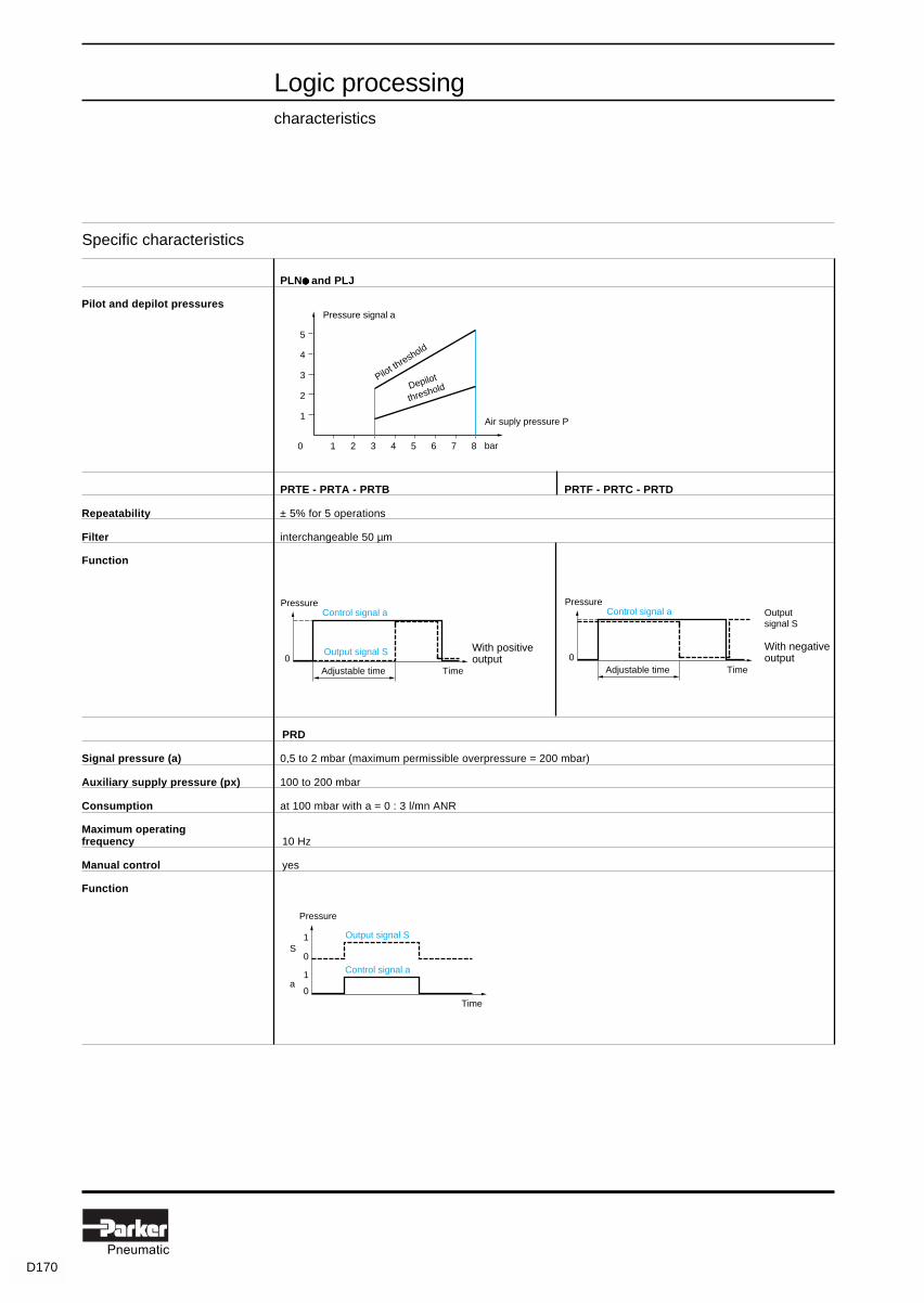
D166Pneumatic
Specific characteristics
Logic processingcharacteristics
PLN● ● ● ● ● and PLJ
Pilot and depilot pressures
PRTE - PRTA - PRTB PRTF - PRTC - PRTD
Repeatability ± 5% for 5 operations
Filter interchangeable 50 µm
Function
PRD
Signal pressure (a) 0,5 to 2 mbar (maximum permissible overpressure = 200 mbar)
Auxiliary supply pressure (px) 100 to 200 mbar
Consumption at 100 mbar with a = 0 : 3 l/mn ANR
Maximum operatingfrequency 10 Hz
Manual control yes
Function
1 2 3 4 5 6 7 80
1
2
3
4
Pressure signal
Air suply pressure P
a
bar
Pilot threshold
Depilot
threshold
5
Control signal aPressure
Output signal S0
Adjustable time Time
With positiveoutput
Control signal aPressure
0Adjustable time Time
With negativeoutput
Output signal S
Control signal a
Pressure
Output signal S
0Time
0
1
1
a
S
D170

D167Pneumatic
Logic processingcharacteristics
...
......
Specific characteristics
PRF
Nozzle Ø 0,3 mm
Filter interchangeable 50 µm
Nozzle consumption
Function
PRS
Consumption - direct current : sealed = 5 W- alternating current : sealed = 6 VA ; inrush = 20 VA
Voltage range 0,9 to 1,05 Un
Standard voltages 24 V ; 48 V ; 24 V ~ ; 48 V ~; 115 V ~; 230 V ~
Rating 100 %
Rated insulation voltage 660 V or ~
Degree of protection IP 65
Manual control yes
Standard NFC 79 300
Connection plug-in connector, Ø 9 mm cable entry - terminal capacity : 1,5 mm2
Function
1 2 3 4 5 6 7 80
2
4
6
8
10
12
14
16
l/mn ANR
Air supplypressure P
Control signal a
Pressure
Output signal S
0Time
0
1
1
a
S
Control signal a
Pressure
Output signal S
0Time
0
1
1
a
S
D171

D168Pneumatic
Logic processingcharacteristics
100
200
24 48 110 220 380
300400500600700 8009001000
20003000
4000
Volts
Volt AmpsVA
2 milli
on op
erati
ons
lth 10
A
5 million operations
10 million operations
Specific characteristics
PRE
Trip pressure 2,2 to 3 bar
Depilot pressure 2 to 2,6 bar
Maximum operatingfrequency 10 Hz
Rated thermal current 10 A
Rated insulation voltage 660 V ... or ~
Degree of protection IP 65
Connection plug-in connector, Ø 9 mm cable entry - terminal capacity : 1,5 mm2
Function N/O contact
Electrical life
PS1P
Fixed trip pressure - 1,3 bar
Adjustable trip pressure 2 to 5 bar
Maximum operatingfrequency 10 Hz
Rated thermal current 10 A
Rated insulation voltage 660 V ... or ~
Degree of protection IP 40
Electrical life Type of circuit :alternating current (switching capacity in VA) direct current (switching capacity in W)
12 V 24 V 48 V 115 V 230 V 12 V 24 V 48 V 115 V 230 V
For 1 million 15 25 56 115 140 17 24 37 50 54operations 54 86 190 370 440 42 58 88 115 105For 2 million - - - - - 10 14 25 40 23operations - - - - - 30 43 70 100 90For 5 million 8 10 14 19 21 - - - - -operations 21 35 82 160 200 - - - - -
Electrical connections Terminals 2 and 4 Terminal 1
Number of Number and size Number of Number and size cable ends of conductors cable ends of conductors
Cable end references per cable end per cable end
DZ5-CE007 2 1x 0,75 1 1 x 0,75
DZ5-CE010 2 1x 1,00 1 1 x 1,00
DZ5-CE015 2 1 x 1,50 1 1 x 1,002 x 0,75 2 2 x 0,75
DZ5-CE0153 - - 2 1 x 1,001 x 1,50
Function C/O contact
D172

D169Pneumatic
= At the time of printing, available on indent only.
Impulse counterswith Ø 4 mm instant connections
PCTA11 PCTB11
PCPA11 PCPS11
PXCA1
Totalising counters
Symbol Counting Mounting Reference Weightrange kg
With 0 Surface PCTA11 0,075pneumatic to mountingor manual 999 999reset
0 Flush mountingto with 60 x 50 mm PCTB11 0,06099 999 bezel
Lockable cover available, see below.
Preselection counters
Symbol Counting Counting Mounting Reference Weightmode range kg
Addition 0 Flush mounting PCPA11 0,115with pneumatic to with 60 x 75 mmor manual 99 999 bezelreset
Subtraction 0 Flush mounting PCPS11 0,110with pneumatic to with 60 x 75 mmor manual 99 999 bezelreset
Lockable cover
With IP 55 lock
Utilisation Reference Weightkg
For 60 x 50 mm bezel PXCA1 0,018on PCTB11
For 60 x 50 mm bezel PXCB1 0,025on PCPA11, PCPS11, PCMA11, PCMB11
Characteristics : page D175Dimensions : page D178
Z
P
A
Z
0Y
Z
P
A
0Y
D173

D170Pneumatic
= At the time of printing, available on indent only.
Timers with digital display
With 60 x 75 mm bezel
Symbol Time Time Reference Weightbase range kg
With pneumatic 1 second 1 second to PCMA11 0,200or manual 27 hoursreset
(lockablecoveravailable 1 minute 1 minute to PCMB11 0,200see page D173) 69 days
Timers with calibrated dial
For 22 x 45 mm cutout
Connection Time Time Reference Weightdiagram base range kg
1 second 2 to PCMF11 0,05030 seconds
Reset (1)
1 second 20 to PCMG11 0,050300 seconds
1 air supply2 output signal
Mounting bezels
Utilisation
For PCMF11 and PCMG11 PXCZM6075 0,015mounting in 60 x 75 mm cutout
For PCMF11 and PCMG11 PXCZM7272 0,015mounting in 72 x 72 mm cutout
Bezels for omega rail mounting
For (irreversible) clip-on mounting of PXCZA35 0,020 PCMF11 and PCMG11 on instant connection subbase
35 mm omega rail latching device PXCZE35 0,010for PXCZA35 subbases
Lockable cover
Degree of protection IP 55
Transparent cover lockable by key PXCB1 0,025for 60 x 75 bezelfor PCPA11, PCPS11, PCPMA11, PCPMB11
(1) Reset by switching off the air supply : the preselected value reappears.
Other versions : these units are available with other dimensions and accessories. Please consult your local Sales Office.
Timerswith Ø 4 mm instant connectionsfor flush mounting
PCMA11
X
Y
mn
P
A
0
X
Y
S
P
A
0
Characteristics : page D175Dimensions : page D178
t
1
2
PXCZM●●●●●●●●●●●●●●●●●●●●
PXCZA35 + PXCZE35
PCMG11
D174

D171Pneumatic
Timers and impulse counterscharacteristics
General characteristics
PCTA PCTB PCPA & PCPS PCMA PCMB PCMF ; PCMG
Operating pressure 3 to 6 bar 3 to 6 bar 3 to 6 bar 3 to 6 bar 3 to 6 bar 2 to 6 bar
Permissible fluids air or neutral gas, 50 µm filtration, preferably unlubricated
Operating temperature 0° C to + 60° C 0° C to + 60° C 0° C to + 60° C 0° C to + 60° C 0° C to + 60° C 0°C to 60°C
Storage temperature - 40° C to + 70° C - 40° C to + 70° C - 40° C to + 70° C - 40° C to + 70° C - 40° C to + 70° C - 40°C to + 70°C
Mechanical life (number ofoperations) with dry air at 6 barand at 20° C - frequency 1 Hz 10 million 10 million 10 million 10 million 10 million 50 million
Connections Ø 4 mm integral instant connection for plastic semi-rigid tube (polyamide and polyurethane)tube size : 2 x 4 mm - 2,7 x 4 mmØ 4 mm external tolerance : + 0,05 (CETOP standard n° RP54P)
- 0,07 flush mounting
Fixing surface mounting flush mounting flush mounting flush mounting flush mounting or clipped on toomega rail
Mounting positions all positions all positions all positions all positions all positions all positions
Maximum operatingfrequency 20 Hz with mark / space ratio of 1/1 - - -
for the first time for the first timeTiming accuracy unit maximum unit maximum
variation = 15 % variation = 15 %- - - ± 2 % ±0,5 % ± 1 %
Time range - - - 1 sec. 1 min. 1 sec
Setting accuracy - - - - - ± 1 %
Pneumatic reset time 150 ms 150 ms 150 ms 150 ms 150 ms 200 ms
Degree of protection - IP 55 with lockable cover -
Manual control reset reset reset reset reset -
normally normally normally normallyFunction - - non passing non passing non passing non passing
Utilisation characteristics
PCTA11 and PCTB11 Count and display the number of impulses received.Pulse input at port Z.Pneumatic reset by port Y.
PCPA11 Supplies a signal at A when the preselected number of pulses has been reached.The required number of impulses is preselected using the keys associated with the lower display.Its display remains unchanged.The pulses to be counted are applied to port Z. Signal A is given as soon as the two displays show the same value.Port Y enables the upper display to be reset by a single pneumatic impulse.
PCPS11 Supplied a signal A when the displayed number reaches zero.The required number of impulses is preselected using the keys associated with the lower display.Pulses are applied to port Z and each pulse subtracts one unit from the preset value.Port Y enables the preselector to be reset to the selected value.
PCMA11 and PCMB11 The required time is preselected using the keys associated with the lower display, which remains unchanged.The unit of time is expressed in seconds or minutes according to the selected time base. Timing starts when asignal appears at X. This signal must be maintained continuously until the output signal appears. Signal A isgiven as soon as the two displays show the same value.Port Y enables the upper display to be reset by a single impulse.
PCMF11 and PCMG11 The duration of timing is set using the pushbutton on the front and is displayed on the graduated drum. As soon aspressure is applied to input 1 timing starts and is independent of the pressure.At the end of the selected time, a signal appears at output 2. The timer can be reset by removing the pressure frominput 1.
D175

D172Pneumatic
55 44
1414
1455
R B
P A
B
A
B
A
R
B
A
3235,5 44 3244 25,5
14
PSM-A12
PSD-A12 PSD-B12
55
48,52215
70,5
PSE-A12 PSM-A10
55
48,52215
97,5
PSE-A12 PSM-A10
27
PSV-A10
Logic processingdimensions
Modular sequencer
Combinable logic elements
Logic elements mounted on 3-port modular subbases
PLLA11 and PLKA11
PLEB12 — PLLB12 — PLKB12 and PLNB12
PZUE12 PLJC10 — PLNC10 — PLKC10 and PLLC10 mounted on PZUC12 and PZUA12
M4 screw
12
1
35
Ø4,2
22 16 16
PZM-L199
16
omega rail
Ø 6 mm instant connection Ø 4 mm instant connection
Line mounted logic elements
22
7
14
28
8
1& &
Ø4,2 22 22 26 6,5 2215
1414
Clip
40
6
Pressureindicator
Ø 4 mm instantconnections
32
1414
40
25
& 1 &
23 34 34
3022
PLJ-C10
34 34
28
PLN-C10
PLK-C10
PLL-C10
PZU-E12
PZU-C12
PZU-C12
PZU-A12
PZU-A12
omegarail
PSDA12 PSDB12 PSEA12 PSMA1O PSMA1OPSEA12
PZML199
D176

D173Pneumatic
4014
14
33 25
28
32
Logic processingdimensions
3 and 4-port modular subbases
Pressure switch
Relays mounted on 3-port modular subbases
Relays mounted on 4-port modular subbases
PS1P1091
PLMA12 and PRDA12
PRTA12 — PRFA12 — PREA12 — PRSA121 and PLND12
PZUE12 — PZUC12 — PZUA12 PZUB12
34
9722
3434343428 30
5465
PRT-A12 PRF-A12 PRE-A12 PRS-A121. PLN-D12
2215
profilé �����
3838
4922
43
4014
14
17,517,517,5 40,5
77,5
n. modules
38
12
305
25Ø4,2
2215
1414
Clip
40
30
10
23
15
Ø4,2
34 34
1414
40
10
omega rail
Ø 3 mm adjusting screw
D177

D174Pneumatic
Timers and impulse countersdimensions
Totalising counters
==
90
27
16 ==
53
==
80 100
38 ==
3XØ4
Z Y
== 32
==
(1) Ø 4 mminstant connections
==
26
62,59
32,5 == 50
==
60
38 50
2XØ4,5
Preselection counters
2XØ4,5
==
23
== 32
X Y
P A
==
51
115,513,5
32,5 48 ==
60
==
62,5
75 51
==
4622=
=
==
2XØ4,5
==
23
== 32
Z Y
P A
==
51
62,513,5
32,5 ==
60
==
62,5
75
Ø 4 mm instant connections
Digital display timers
Preselection counters
PCPA11 and PCPS11
PCTA11 PCTB11
PCMA11 and PCMB11
Ø 4 mm instant connections
PCMF11 and PCMG1160
58,6
3,9
12 max.
2,5 7,8
58,6
16
11,5
21,8
10,4
Ø 4 mm instant connections
48
27,2
24
D178