Embed Size (px)
Citation preview
Telemotive Pre-engineered MLTX Transmitter
Remote Crane Controls
May 2009 Part Number: 178-00161-R2
TCMLTX-0 ©Copyright 2009 Magnetek Material Handling

Telemotive MLTX Transmitter Instruction Manual 5/8/2009
Page 2 of 19
Your New Radio Remote
Thank you for your purchase of Magnetek’s Telemotive® brand MLTX Radio Remote Crane Control. Magnetek has set a whole new standard in radio-remote performance, dependability, and value with this unique new line of belly box transmitters. Without a doubt, our Telemotive MLTX is the ultimate solution for having precise, undeterred, and safe control of your material.
If your product ever needs modification or service, please contact one of our representatives at the following locations: U.S. Service Information For questions regarding service or technical information contact: 1-866-MAG-SERV (1-866-624-7378). Magnetek Material Handling N49 W13650 Campbell Drive Menomonee Falls, WI 53051 Telephone: 800-288-8178 Website: www.magnetekmh.com e-mail: [email protected] Fax Numbers: Main: 800-298-3503 Sales: 262-783-3510 Service: 262-783-3508 Canada Service Information: 2610 Dunwin Drive Mississauga, Ontario L5L 1J5 Canada Phone: 1-800-792-7253 Fax: 1-905-828-5707
©2009 MAGNETEK MATERIAL HANDLING
All rights reserved. This notice applies to all copyrighted materials included with this product, including, but not limited to, this manual and software embodied within the product. This manual is intended for the sole use of the persons to whom it was provided, and any unauthorized distribution of the manual or dispersal of its contents is strictly forbidden. This manual may not be reproduced in whole or in part by any means whatsoever without the expressed written permission of MAGNETEK.

Telemotive MLTX Transmitter Instruction Manual 5/8/2009
Page 3 of 19
TABLE OF CONTENTS 1.1: CRITICAL INSTALLATION CONSIDERATIONS ............................................................................. 5 1.2: GENERAL .............................................................................................................................................. 6 1.3: PERSONS AUTHORIZED TO OPERATE RADIO CONTROLLED CRANES.................................. 6 1.4: OPERATING AREA .............................................................................................................................. 6 1.5: TRANSMITTER UNIT .......................................................................................................................... 6 1.6: OPERATING THE CRANE ................................................................................................................... 6 1.6.1: PRE-OPERATION TEST .................................................................................................................... 6 1.7: CRANE MAINTENANCE AND REPAIR............................................................................................. 7 1.8: CONDITION OF THE RADIO CONTROLLED CRANE..................................................................... 7 1.9: BATTERIES ........................................................................................................................................... 7 1.10: BATTERY HANDLING....................................................................................................................... 7 1.11: BATTERY CHARGING....................................................................................................................... 7 1.12: BATTERY DISPOSAL ........................................................................................................................ 8 2.1: MLTX TRANSMITTER STANDARD CONFIGURATION AND OPERATION ............................... 9 2.2: “ON-OFF” PUSH-BUTTON (TURNS TRANSMITTER AND RECEIVER ON OR OFF) ............... 10 2.3: “E-STOP” (FOR EMERGENCY STOPPING ONLY)......................................................................... 10 2.4: “BATTERY ” TRANSMITTER LED INDICATOR............................................................................ 10 2.5: LEVERS................................................................................................................................................ 10 2.6: “A, B, OR BOTH” ROTARY SELECTOR SWITCH.......................................................................... 10 2.7: “IND OR TANDEM” ROTARY SELECTOR SWITCH ..................................................................... 10 2.8: “AUX 1, AUX 2, AUX 3 AND AUX 4” AUXILIARY SWITCHES................................................... 10 2.9: TIME-OUT-TIMER.............................................................................................................................. 11 2.10: TRANSMITTER SWITCH PROGRAMMING.................................................................................. 11 2.10.1: SW3 POSITION 8 TIME-OUT-TIMER DISABLE (NORMALLY KEEP TURNED “OFF”) ...... 11 2.11: SW4 POSITION 1-2 MODE ENABLE (INTELESMART)............................................................... 11 2.12 : SW4 POSITION 1-2 MODE ENABLE, (INTELESMART) TR-24 (10K16-24 SYSTEMS) ........... 11 2.13: SW4 POSITION 3 DISABLE TANDEM FOR HOIST AND TROLLEY......................................... 12 2.14: SW4 POSITION 4 INVERT CRANE SELECT AUX. OUTPUTS.................................................... 12 2.15: SW4 POSITIONS 5-7 EXTENDED CRANE CONTROL (STANDARD ALL “OFF”) ................... 12 2.16: PRE-ENGINEERED MLTX TRANSMITTER BOARD SETUP INFORMATION ......................... 13 2.17: CABLE CONNECTIONS................................................................................................................... 14 2.18: SETTING ACCESS CODE ................................................................................................................ 14 2.19: CHECK DATA ................................................................................................................................... 14 2.20: BATTERY MONITOR....................................................................................................................... 14 2.21: ANALOG VOLTAGE REFERENCE................................................................................................. 14 2.22: BATTERIES ....................................................................................................................................... 14 2.23: REPROGRAMMING THE PART 15 TRANSMITTER SYNTHESIZER ........................................ 15 2.24: CHANNEL AND FREQUENCY DESIGNATIONS BY COUNT .................................................... 16 2.25: ASSEMBLY AND REPLACEMENT PARTS................................................................................... 17

Telemotive MLTX Transmitter Instruction Manual 5/8/2009
Page 4 of 19
WARNINGS and CAUTIONS
Throughout this document WARNING and CAUTION statements have been deliberately placed to
highlight items critical to the protection of personnel and equipment.
WARNING – A warning highlights an essential operating or maintenance procedure, practice, etc. which if not strictly observed, could result in injury or death of personnel, or long term physical hazards. Warnings are highlighted as shown below:
WARNING
CAUTION – A caution highlights an essential operating or maintenance procedure, practice, etc. which if not strictly observed, could result in damage to, or destruction of equipment, or loss of functional effectiveness. Cautions are highlighted as shown below:
CAUTION
WARNINGS and CAUTIONS SHOULD NEVER BE DISREGARDED.
The safety rules in this section are not intended to replace any rules or regulations of any applicable local, state, or federal governing organizations. Always follow your local lockout and tagout procedure when maintaining any radio equipment. The following information is intended to be used in conjunction with other rules or regulations already in existence. It is important to read all of the safety information contained in this section before installing or operating the Radio Control System.

Telemotive MLTX Transmitter Instruction Manual 5/8/2009
Page 5 of 19
1.1: CRITICAL INSTALLATION CONSIDERATIONS
WARNING
ALL EQUIPMENT MUST HAVE A MAINLINE CONTACTOR INSTALLED AND ALL TRACKED CRANES AND SIMILAR EQUIPMENT MUST HAVE A BRAKE INSTALLED. FAILURE TO FOLLOW THIS WARNING COULD RESULT IN SERIOUS INJURY OR DEATH AND DAMAGE TO EQUIPMENT.
WARNING
ON ALL REMOTE CONTROLLED CRANES AN AUDIBLE AND/OR VISUAL WARNING MEANS MUST BE PROVIDED. THESE AUDIBLE AND/OR VISUAL WARNING DEVICES MUST MEET ALL GOVERNMENTAL REQUIREMENTS. FAILURE TO FOLLOW THIS WARNING COULD RESULT IN SERIOUS INJURY OR DEATH AND DAMAGE TO EQUIPMENT.
WARNING
PLEASE FOLLOW YOUR LOCAL LOCKOUT TAGOUT PROCEDURE BEFORE MAINTAINING ANY REMOTE CONTROL EQUIPMENT. ALWAYS REMOVE ALL ELECTRICAL POWER FROM THE CRANE OR MACHINERY BEFORE ATTEMPTING ANY INSTALLATION PROCEDURES. DE-ENERGIZE AND TAGOUT ALL SOURCES OF ELECTRICAL POWER BEFORE TOUCH TESTING ANY EQUIPMENT. FAILURE TO FOLLOW THIS WARNING COULD RESULT IN SERIOUS INJURY OR DEATH AND DAMAGE TO EQUIPMENT.
WARNING
THE DIRECT OUTPUTS OF THIS PRODUCT ARE NOT DESIGNED TO INTERFACE DIRECTLY TO TWO STATE SAFETY CRITICAL MAINTAINED FUNCTIONS, I.E., MAGNETS, VACUUM LIFTS, PUMPS, EMERGENCY EQUIPMENT, ETC. A MECHANICALLY LOCKING INTERMEDIATE RELAY SYSTEM WITH SEPARATE POWER CONSIDERATIONS MUST BE PROVIDED. FAILURE TO FOLLOW THIS WARNING COULD RESULT IN SERIOUS INJURY OR DEATH AND DAMAGE TO EQUIPMENT.

Telemotive MLTX Transmitter Instruction Manual 5/8/2009
Page 6 of 19
1.2: GENERAL
Radio controlled overhead cranes and other material handling equipment operate in several directions. They are large, bulky pieces of equipment that handle heavy loads efficiently at high speeds. Quite frequently, the equipment is operated in areas where people are working on the floor below. The crane operator must exercise extreme caution at all times. Workers must constantly be alert to avoid accidents. If radio controlled material-handling equipment is operated from the cab, special care must be taken to secure the transmitter.
1.3: PERSONS AUTHORIZED TO OPERATE RADIO CONTROLLED CRANES
Only authorized and properly trained persons designated by management should be permitted to operate ra-dio-controlled cranes.
Radio controlled cranes should not be operated by any person who cannot read or understand signs, notices and operating instructions that pertain to the crane.
Radio controlled cranes should not be operated by any person with insufficient eyesight or hearing or by any person who may be suffering from a disorder or illness or is taking any medication that may cause loss of crane control. 1.4: OPERATING AREA
Aisles between equipment, stock, etc., should be free of obstructions so the crane operator can move freely. These aisles should be a minimum of three feet (one meter) wide, or meet local regulations.
Crane operators should always position themselves for the best view of the crane they are controlling. The crane should never be operated blindly. The operator should stay as close to the crane load as possible. Operators should never position themselves in a "pinch" point. 1.5: TRANSMITTER UNIT
Transmitter switches should never be mechanically blocked ON or OFF for any crane motion. When not in use turn the transmitter OFF. A secure storage space should be provided for the transmitter unit and the transmitter unit should always be placed there when not in use. This precaution will prevent unauthorized people from operating the crane.
Spare transmitters should be stored in a secure storage space and only removed from the storage space after the current transmitter in use has been turned OFF, taken out of the service area and secured. 1.6: OPERATING THE CRANE 1.6.1: PRE-OPERATION TEST At the start of each work shift, or when a new operator takes control of the crane, operators should do, as a minimum, the following steps before making lifts with any crane or hoist:
Test all warning devices.
Test all direction and speed controls for both bridge and trolley travel.
Test the transmitter emergency stop.
Test the hoist brake to verify there is no drift without a load.
If any crane or hoist fails any of the above tests notify the supervisor then lockout and tagout for repair.
Telemotive MLTX Transmitter Instruction Manual 5/8/2009
Page 7 of 19
1.7: CRANE MAINTENANCE AND REPAIR
Qualified personnel should must maintain a regularly (i.e., such as monthly) scheduled crane inspection. During this crane inspection the functionality and safety of the crane remote control must also be tested. 1.8: CONDITION OF THE RADIO CONTROLLED CRANE
If the crane fails to respond properly, the crane operator(s) should notify their supervisor. When serious conditions are noticed (conditions that make the crane unsafe to operate), the crane should be shut down immediately and the supervisor notified. 1.9: BATTERIES
WARNING KNOW AND FOLLOW PROPER BATTERY HANDLING, CHARGING AND DISPOSAL PRO-CEDURES. IMPROPER BATTERY PROCEDURES CAN CAUSE BATTERIES TO EXPLODE OR DO OTHER SERIOUS DAMAGE. FAILURE TO FOLLOW THIS WARNING COULD RESULT IN SERI-OUS INJURY OR DEATH AND DAMAGE TO EQUIPMENT.
1.10: BATTERY HANDLING
Use only batteries approved by Telemotive for the specific product.
Do not dispose of a battery pack in fire; it may explode.
Do not attempt to open the battery pack.
Do not short circuit battery.
For use in hazardous locations, only use the hazardous location type transmitters and batteries.
Keep the battery pack environment cool during charging operation and storage, (i.e., not in direct sunlight or close to a heating source). 1.11: BATTERY CHARGING
For those transmitters equipped with battery chargers, please familiarize all users with the instructions of the charger before attempting to use.
Do not attempt to charge non-rechargeable battery packs.
Avoid charging the battery pack for more than 24 hours at a time. For best battery life, the battery should be removed from the charger after one to two days of charging.
Do not charge batteries in a hazardous environment.
Do not short charger.
Do not attempt to charge a damaged battery.
Do not attempt to use a battery that is leaking, swollen or corroded.

Telemotive MLTX Transmitter Instruction Manual 5/8/2009
Page 8 of 19
Charger units are not intended for outdoor use. Use only indoors.
The single unit charger for the BT114-0 is E10757-0. You can attach up to two more E10757-1 (piggy back chargers) to the E10757-0 charger. The typical recharge time for a completely discharged battery is approximately three hours. While NiMH batteries give improved performance over NiCAD, any rechargeable battery will give its best performance if the battery is fully discharged before recharging. If you have any questions, please refer to your charger manual. Refer to your local regulations for the disposal of any battery product. 1.12: BATTERY DISPOSAL
Before disposing of batteries consult local and governmental regulatory requirements for proper disposal procedure. Use only Telemotive approved chargers for the appropriate battery pack.

Telemotive MLTX Transmitter Instruction Manual 5/8/2009
Page 9 of 19
BRIDGE TROLLEY HOIST
HOIST
AUX 1
AUX 2 AUX 3 AUX 4 E STOP ON - OFF
BATTERY
AUX 5 AUX 4
2.1: MLTX TRANSMITTER STANDARD CONFIGURATION AND OPERATION
WARNING BEFORE OPERATING THE TRANSMITTER FAMILIARIZE YOURSELF WITH ALL SAFETY INFORMATION IN THIS MANUAL, THE CORRESPONDING RECEIVER SYSTEM MANUAL, APPROPRIATE MANUAL SUPPLEMENTS AND ANY OTHER LOCAL, STATE, OR FEDERAL RULES OR REGULATIONS ALREADY IN EXISTENCE. FAILURE TO FOLLOW THIS WARNING COULD RESULT IN SERIOUS INJURY OR DEATH AND DAMAGE TO EQUIPMENT.
Figure 1. Pre-engineered MLTX Control
“MLTX-4L-3M-3S” has 4 Levers and 3 Speeds
“MLTX-3L-3M-3S” has 3 Levers and 3 Speeds
BRIDGE TROLLEY HOIST
AUX 1
AUX 2
AUX 3
AUX 4 E STOP ON-OFF BATTERY
B A BOTH
“MLTX-3L-3M-2S” has 3 Levers and 2 Speeds “MLTX-3L-5M-3S” has 3 Levers and 3 Speeds “MLTX-3L-3M-5S” has 3 Levers and 5 Speeds
BRIDGE TROLLEY HOIST AUX
HOIST
AUX 1 AUX 2
AUX 3 AUX 4 E STOP ON - OFF
BATTERY
TANDEM IND
AUX 1
AUX 2
AUX 3
AUX 4 E STOP ON-OFF
BRIDGE AUX TROLLEY MAIN TROLLEY HOIST AUX HOIST
BATTERY
TANDEM IND.
TANDEM IND.
“MLTX-5L-5M-3S” has 5 Levers and 3 Speeds
Telemotive MLTX Transmitter Instruction Manual 5/8/2009
Page 10 of 19
Sections 2-1. through 2-8. Describe the functional operation of the MLTX. Please refer to Figure 1 for typical Pre-engineered MLTX Control Layouts.
2.2: “ON-OFF” PUSH-BUTTON (TURNS TRANSMITTER AND RECEIVER ON OR OFF)
Pressing the ON/OFF push-button switch turns the transmitter and the receiver on. If the transmitter is on, the BATTERY light is on or flashing. Pushing the ON/OFF pushbutton again will turn the transmitter and receiver off. If the transmitter is out of range of the receiver, the receiver will not turn off until it times out (for those units with receiver time-out-timer set active).
2.3: “E-STOP” (FOR EMERGENCY STOPPING ONLY)
When depressed, all equipment movement is immediately stopped. Under normal operating conditions, the E-STOP must be in the raised position. The transmitter must be turned off and on again to restore normal operation. The E-Stop is to be used for emergency stopping only, not for normal system shut down. The E-STOP will not function with the optional key switch turned off. 2.4: “BATTERY ” TRANSMITTER LED INDICATOR
The transmitter LED (red) indicates on, transmitting and low battery voltage. A slow flash rate indicates the unit is on. A rapid flash rate indicates a unit is transmitting (when a function or control is activated). If the battery goes below a safe level the, LED will not light. Replace the battery immediately. 2.5: LEVERS
To activate motor functions, press and hold the push-button or lever that corresponds to the desired motion. To activate higher speed functions, for those models so equipped, press the motion switch or lever further. 2.6: “A, B, OR BOTH” ROTARY SELECTOR SWITCH (Only for systems with one lever for Main and Aux Hoist or Trolley)
This rotary selector switch is used with the main and auxiliary hoist/trolley. Position “A” activates the hoist/trolley lever to control only the main hoist/trolley. Position “B” activates the hoist/trolley lever to control only the auxiliary hoist/trolley. Position “BOTH” activates the hoist/trolley lever to control both the main and auxiliary hoist/trolley at the same time, in tandem. 2.7: “IND OR TANDEM” ROTARY SELECTOR SWITCH (Only for systems with two separate levers, Main and AUX, for Hoist and/or Trolley)
This rotary selector switch is used with the main and auxiliary hoist. In the “IND” (Independent) position, the main hoist/trolley and aux hoist/trolley are controlled by their respective levers only. In the “TANDEM” position, the main hoist/trolley lever controls both the main and auxiliary hoist/trolley at the same time in tandem. 2.8: “AUX 1, AUX 2, AUX 3 AND AUX 4” AUXILIARY SWITCHES
These switches activate special function relays that control items such as alarms or lights depending on how the receiver is wired. The switches are momentary and activate the function as long as the switch is depressed.

Telemotive MLTX Transmitter Instruction Manual 5/8/2009
Page 11 of 19
2.9: TIME-OUT-TIMER
Unless this function is disabled, the transmitter will turn itself off if not used for 15 minutes.
2.10: TRANSMITTER SWITCH PROGRAMMING
Sections 2.10.1 through 2.18 describe transmitter Switches SW3 and SW4 Programming. (See Figure 2 for physical location of transmitter switches SW3 and SW4).
2.10.1: SW3 POSITION 8 TIME-OUT-TIMER DISABLE (NORMALLY KEEP TURNED “OFF”) The transmitter has an approximate 15-minute time-out-timer. If the transmitter is not used for over 15 minutes it will shut down. This transmitter time-out-timer function is transmitter dip switch selectable. Turning SW3-8 “ON” disables the time-out-timer. Turning SW3-8 “OFF” enables the time-out-timer. 2.11: SW4 POSITION 1-2 MODE ENABLE INTELESMART TR12-Mini, TR12-PDA (10K12 Systems)
Mode 1, SW4 1-2 all “OFF”: The standard 10K12 2-speed system comes configured this way from the factory with three 2-speed controls and three auxiliaries (controlled by the toggle switches, the rotary is non-functional).
Mode 2, SW4 1 turned “OFF” and SW4 2 turned “ON”: The 10K12 2-speed system configured this way is able to control four 2-speed motion controls and no auxiliaries (bridge, trolley, main and aux hoist). The rotary selector switch functions are A main hoist, B aux hoist and both main and aux hoist (the toggle switches are non-functional).
Mode 3, SW4 1 and 2 turned “ON”: The 10K12 2-speed system will control up to 5 motors using the rotary selector switch. This mode reconfigures two of the 10K12 auxiliary outputs (Aux 1 and Aux 2) to be external motor select functions by the rotary switch. In this mode, the auxiliary toggle switch Aux 1 and Aux 2 are disabled. When the rotary switch is in the A or B position, Aux 1 relay or Aux 2 relay will close, respectively, whenever trolley or hoist pushbuttons are pressed. When the rotary switch is in BOTH position both Aux 1 and Aux 2 relays will close. 2.12 : SW4 POSITION 1-2 MODE ENABLE, INTELESMART TR-24 (10K16-24 SYSTEMS)
Mode 1, SW4-1&2 all “OFF”: The 10K16 3-speed system comes configured this way from the factory with three 3-speed controls and six auxiliaries. The 10K24 3-speed system comes configured this way from the factory with three 3-speed controls and four auxiliaries.
Mode 2, SW4-1 turned “ON” and SW4-2 turned “OFF”. The 10K24 configured this way provides hoist, trolley and bridge with independent select functions. The system utilizes separate select relays with common speed and direction.
Mode 3, SW4-1 turned “OFF” and SW4 2 turned “ON”. The 10K24 configured this way has four motor 3-speed selectability by the rotary switch. Two hoists, one trolley and one bridge with main hoist (A), auxiliary hoist (B), and “both” (BOTH) main and auxiliary hoists are selectable by the rotary switch.
WARNING DO NOT ASSUME THE POWER IS OFF IN THE RECEIVER BECAUSE THE TRANSMITTER IS TURNED OFF. FAILURE TO FOLLOW THIS WARNING COULD RESULT IN SERIOUS INJURY OR DEATH AND DAMAGE TO EQUIPMENT.
Telemotive MLTX Transmitter Instruction Manual 5/8/2009
Page 12 of 19
2.13: SW4 POSITION 3 DISABLE TANDEM FOR HOIST AND TROLLEY (Normally keep turned “OFF”) For cranes with auxiliary hoists and/or trolleys, turning this switch “ON” disables the transmitter selector switch “BOTH” position (both function) that selects tandem operation of hoist or trolley. 2.14: SW4 POSITION 4 INVERT CRANE SELECT AUX. OUTPUTS (Normally keep turned “OFF”) For cranes that use the select function only, turning this switch “ON” inverts the select function operation so that the relay closes for the unselected function. 2.15: SW4 POSITIONS 5-7 EXTENDED CRANE CONTROL (STANDARD ALL “OFF”) The Pre-engineered MLTX transmitters are available with extended crane control configurations. These options are switch configurable on the transmitter. The eight-position dip switches SW3 and SW4 on the transmitter can provide all configurations with a single transmitter CPU EPROM for a particular transmitter style. The programming tables with the transmitter extended crane control configurations are found in the appropriate receiver manual. In these sections, if the MLTX is not specifically listed, use the switch programming guide for the configurations labeled SLTX or JLTX (they are the same).
Telemotive MLTX Transmitter Instruction Manual 5/8/2009
Page 13 of 19
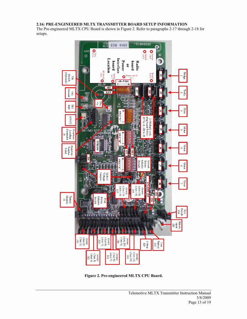
2.16: PRE-ENGINEERED MLTX TRANSMITTER BOARD SETUP INFORMATION The Pre-engineered MLTX CPU Board is shown in Figure 2. Refer to paragraphs 2-17 through 2-18 for setups.
Figure 2. Pre-engineered MLTX CPU Board.

Telemotive MLTX Transmitter Instruction Manual 5/8/2009
Page 14 of 19
2.17: CABLE CONNECTIONS
When reconnecting cables, the labels in Figure 2 correspond to the connection points for controls, inputs and indicators. Plug appropriate controls, inputs and indicators into their corresponding labeled connectors, by connection numbers. Cables are marked with the connector number. Note: Please ensure that cables are not pinched when closing the transmitter 2.18: SETTING ACCESS CODE
The access code is set at the factory and should not be changed unless absolutely necessary. If a spare transmitter unit is used, the receiver unit access code should be changed to match the access code of the spare transmitter unit. Access codes are printed on a label on the outside of any transmitter and may be matched to “A” and “B” on the receiver microcomputer module without having to open the transmitter housing. Switch SW2 (B) in the transmitter must match switch S4 (B) on the receiver microcomputer module and switch SW1 (A) in the transmitter must match switch S5 (A) on the microcomputer module. 2.19: CHECK DATA 1). For data input use Data pin on RF Module. 2). Use RF SW pin on RF Module for External Trigger input. 3). Use TP2 for Ground. 2.20: BATTERY MONITOR
Factory preset to 5.8 Volts (not adjustable.) 2.21: ANALOG VOLTAGE REFERENCE Controls lever and joystick range. V+ (TP3) factory adjusted with RPOT2. 2.22: BATTERIES Two batteries are available, a disposable alkaline battery (9V, BT113-0), a rechargeable NiMH (7.2V, BT114-0), and a rechargeable NiMH (12V, BT115-0). The MLTX CPU board is equipped with battery voltage jumpers that allow different battery voltages to be utilized depending on the application. The jumpers must be set correctly or the MLTX will not function properly. Ensure that JU3 and JU4 are both set properly for your transmitter’s battery. For 9V disposable alkaline and 7.2V rechargeable NiMH, JU3 and JU4 must be set for 7.2V. For 12V rechargeable NiMH, JU3 and JU4 must be set for 12V.
Telemotive MLTX Transmitter Instruction Manual 5/8/2009
Page 15 of 19
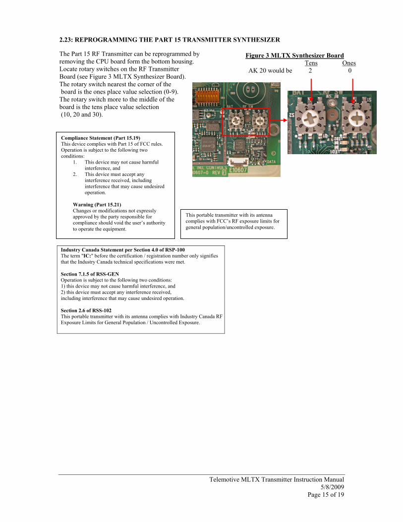
2.23: REPROGRAMMING THE PART 15 TRANSMITTER SYNTHESIZER
The Part 15 RF Transmitter can be reprogrammed by removing the CPU board form the bottom housing. Locate rotary switches on the RF Transmitter Board (see Figure 3 MLTX Synthesizer Board). The rotary switch nearest the corner of the board is the ones place value selection (0-9). The rotary switch more to the middle of the board is the tens place value selection (10, 20 and 30).
Figure 3 MLTX Synthesizer Board Tens Ones
AK 20 would be 2 0
Compliance Statement (Part 15.19) This device complies with Part 15 of FCC rules. Operation is subject to the following two conditions:
1. This device may not cause harmful interference, and
2. This device must accept any interference received, including interference that may cause undesired operation.
Warning (Part 15.21) Changes or modifications not expressly approved by the party responsible for compliance should void the user’s authority to operate the equipment.
This portable transmitter with its antenna complies with FCC’s RF exposure limits for general population/uncontrolled exposure.
Industry Canada Statement per Section 4.0 of RSP-100 The term "IC:" before the certification / registration number only signifies that the Industry Canada technical specifications were met. Section 7.1.5 of RSS-GEN Operation is subject to the following two conditions: 1) this device may not cause harmful interference, and 2) this device must accept any interference received, including interference that may cause undesired operation. Section 2.6 of RSS-102 This portable transmitter with its antenna complies with Industry Canada RF Exposure Limits for General Population / Uncontrolled Exposure.

Telemotive MLTX Transmitter Instruction Manual 5/8/2009
Page 16 of 19
2.24: CHANNEL AND FREQUENCY DESIGNATIONS BY COUNT
Indicator Channel Actual Count Designator Frequency
01) AK01 439.8 MHz 02) AK02 439.6 MHz 03) AK03 439.4 MHz 04) AK04 439.2 MHz 05) AK05 439.0 MHz 06) AK06 438.8 MHz 07) AK07 438.6 MHz 08) AK08 438.4 MHz 09) AK09 438.2 MHz 10) AK10 438.0 MHz 11) AK11 437.8 MHz 12) AK12 437.6 MHz 13) AK13 437.4 MHz 14) AK14 437.2 MHz 15) AK15 437.0 MHz 16) AK16 436.8 MHz 17) AK17 436.6 MHz 18) AK18 436.4 MHz 19) AK19 436.2 MHz 20) AK20 436.0 MHz 21) AKA00 433.125 MHz 22) AKA01 433.325 MHz 23) AKA02 433.525 MHz 24) AKA03 433.725 MHz 25) AKA04 433.925 MHz 26) AKA05 434.125 MHz 27) AKA06 434.325 MHz 28) AKA07 434.525 MHz 29) AKA08 434.725 MHz 38) AK38 432.4 MHz 50) AK50 430.0 MHz
Telemotive MLTX Transmitter Instruction Manual 5/8/2009
Page 17 of 19
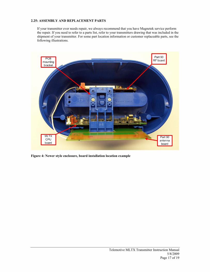
2.25: ASSEMBLY AND REPLACEMENT PARTS If your transmitter ever needs repair, we always recommend that you have Magnetek service perform the repair. If you need to refer to a parts list, refer to your transmitters drawing that was included in the shipment of your transmitter. For some part location information or customer replaceable parts, see the following illustrations.
Figure 4: Newer style enclosure, board installation location example

Telemotive MLTX Transmitter Instruction Manual 5/8/2009
Page 18 of 19
Figure 5: Older style enclosure, board installation location example

Telemotive MLTX Transmitter Instruction Manual 5/8/2009
Page 19 of 19
Figure 6: Customer Replaceable Parts