Embed Size (px)
Citation preview
TELEMECANIQUE MOTOR CONTROLLER
Use and Instructions
Bachelor’s thesis
Degree Program in Automation Engineering
Valkeakoski 20th June 2012
Yaw Adjei
ABSTRACT
Valkeakoski
Degree Programme in Automation Engineering
Author Yaw Adjei 2012
Subject of Bachelor’s thesis Telemecanique motor controller – use and in-
structions
ABSTRACT
Electric motors are versatile electrical machines used in the industry and
in many domestic appliances. They convert electrical energy into mechan-
ical (rotational) energy. Following the advent of Induction motors, which
are simple, rugged, reliable, low cost and highly efficient, they need no ex-
tra starting motor or brushes, much of the modern day motor controllers
are geared induction motors.
Telemecanique Motors Controllers Te Sys LUCM1XBL and Te Sys
LUCBX6BL are Direct On-Line (DOL) motor starters which could be
used to:
give protection and control to 3-phase motors;
o breaking function,
o overload and short-circuit protection,
o thermal overload protection and power switching.
LUCM1XBL can also be used for single-phase motors and offers the fol-
lowing added advantage:
control the application;
o protection function alarms,
o application monitoring (running time, number of faults, motor
current values, ...),
o logs (last 5 faults saved, together with motor parameter values).
This project seeks to provide electrical connection diagrams for the motor
controller and instruction manual so that people with only the basic
knowledge in electrical could safely connect, program/set and use the con-
trollers thus, offering the possibility for the controllers to be used for stu-
dent laboratory works. With this information, users could decide with
which abnormal condition(s) the controller should give a warning signal
and when to turn/switch the motor off.
Keywords Motor control, protection and monitoring.
Pages 28 p. + appendices 7 p.
CONTENTS
1 INTRODUCTION ....................................................................................................... 1
2 MOTORS .................................................................................................................... 2
2.1 Squirrel Cage Motor ............................................................................................ 3 2.1.1 Voltage .................................................................................................... 4 2.1.2 Power Factor (p.f.) ................................................................................... 5 2.1.3 Speed ....................................................................................................... 6 2.1.4 Torque ...................................................................................................... 7
2.2 Starting Methods ................................................................................................. 7
2.2.1 Direct-on-line (D.O.L.) ............................................................................ 7
2.2.2 Star-Delta (Y-Δ) Starting ......................................................................... 8 2.2.3 Frequency Converter ............................................................................. 10 2.2.4 Softstarter .............................................................................................. 11
3 TELEMECANIQUE MOTOR CONTROLLERS .................................................... 13
3.1 Te Sys LUCBX6BL .......................................................................................... 13 3.1.1 LUB12 ................................................................................................... 13 3.1.2 Te Sys LUCBX6BL Installation ........................................................... 17
3.2 Te Sys LUCM1XBL ......................................................................................... 19 3.2.1 Te Sys LUCM1XBL Installation ........................................................... 20
3.2.2 Service Temperature .............................................................................. 21 3.2.3 Te Sys LUCM1XBL Connection .......................................................... 21
3.2.4 Setting/Programming of the Te Sys LUCM1XBL ................................ 22 3.2.5 Power up and operating modes .............................................................. 23
3.2.6 Configuration (Config) Menu Programme ............................................ 23 3.2.7 Main Menu Programme ......................................................................... 24
CONCLUSION .............................................................................................................. 27
SOURCES ...................................................................................................................... 28
Appendix 1 DEFAULT SETTINGS AND OPTIONAL VALUES FO THE
LUCM1XBL
Appendix 2 REMOTE MONITORING AND CONFIGURATION OF THE TE SYS
CONTROL UNITS

Telemecanique motor controller – use and instructions
1
1 INTRODUCTION
This project was made at HAMK AutoMaint Lab, that is owned and run
by Hämeen Ammattikorkeakoulu (HAMK University of Applied Scienc-
es). In this project, the uses of Telemecanique motor controllers Te Sys
LUCM1XBL and Te Sys LUCBX6BL were explained and the instructions
for its use provided.
The monitoring and controlling of three (3) phase induction motors has
become the priority of most motor control designers and manufacturers
with induction motors becoming the most used motors in the industry due
to their comparable advantages. Hence, the controlling and monitoring of
three (3) phase induction motors has become an indispensable objective in
most industries.
This project seeks to provide connection diagrams, user’s manuals for the
Telemecanique Controllers Te Sys LUCM1XBL and Te Sys LUCBX6BL.
I wish to thank HAMK AutoMaint Unit for giving me this opportunity to
undertake this thesis project as well as the whole HAMK institution. My
profound gratitude also goes to Osmo Leiniäinen, my project supervisor
and Hannu Pohjasto for their immense contribution and support.
Telemecanique motor controller – use and instructions
2
2 MOTORS
Electrical Motors are generally referred to as electrical machines in that,
well designed electric motors at times operate as generators. Rotating elec-
trical machines could be used as a motor or a generator.
There are basically, AC and DC electric motors, based on the type of op-
erating power supply. In AC motors, there are single phase (1-φ) and three
phase (3- φ) motors. AC motors are usually either synchronous or asyn-
chronous (induction) motors. The induction machine has gained popularity
in the market due to its simple construction, durability, robustness, high
efficiency and ease of starting.
Motors vibrate mechanically when in use. Motors are also used to drive
different systems such as conveyors, pumps, fans and so on, hence motors
need to be securely fixed to a place, usually referred to as mounting, to en-
sure good mechanical performance during use. Motor mounting may be
implemented as foot or flange mount or as both.
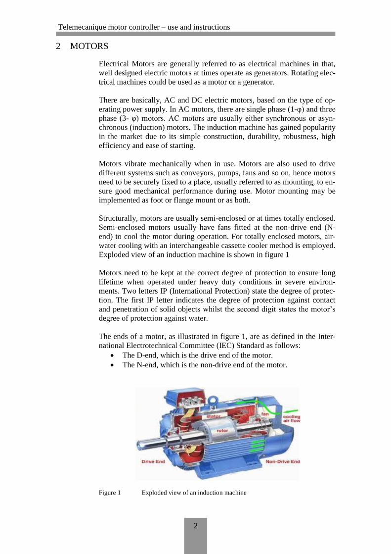
Structurally, motors are usually semi-enclosed or at times totally enclosed.
Semi-enclosed motors usually have fans fitted at the non-drive end (N-
end) to cool the motor during operation. For totally enclosed motors, air-
water cooling with an interchangeable cassette cooler method is employed.
Exploded view of an induction machine is shown in figure 1
Motors need to be kept at the correct degree of protection to ensure long
lifetime when operated under heavy duty conditions in severe environ-
ments. Two letters IP (International Protection) state the degree of protec-
tion. The first IP letter indicates the degree of protection against contact
and penetration of solid objects whilst the second digit states the motor’s
degree of protection against water.
The ends of a motor, as illustrated in figure 1, are as defined in the Inter-
national Electrotechnical Committee (IEC) Standard as follows:
The D-end, which is the drive end of the motor.
The N-end, which is the non-drive end of the motor.
Figure 1 Exploded view of an induction machine
Telemecanique motor controller – use and instructions
3
2.1 Squirrel cage motor
The Squirrel cage motor is the focus here because of its de-facto market
dominance. The squirrel cage motor consists of a stationary stator and ro-
tating rotor. The stator is firmly fixed into the motor casing known as the
yoke or core. The stator is made of laminated iron plates to reduce eddy
current effects from ac operation. The stator has axial grooves known as
slots to accommodate the stator windings needed in the creation of a mag-
netic field for operation. Power supplied to the motor is connected to the
stator.
The rotor of a squirrel cage motor is comprised of a cylindrical laminated
core with parallel slots for carrying the rotor conductors (which are heavy
bars of copper, aluminium, or alloys). The rotor bars are electrically con-
nected by brazing, welding or bolting to two (2) heavy short- circuiting
end-rings, which create permanently short-circuited rotor bars, hence the
name ‘squirrel cage’.
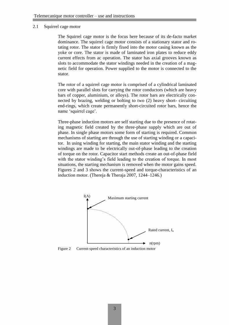
Three-phase induction motors are self starting due to the presence of rotat-
ing magnetic field created by the three-phase supply which are out of
phase. In single phase motors some form of starting is required. Common
mechanisms of starting are through the use of starting winding or a capaci-
tor. In using winding for starting, the main stator winding and the starting
windings are made to be electrically out-of-phase leading to the creation
of torque on the rotor. Capacitor start methods create an out-of-phase field
with the stator winding’s field leading to the creation of torque. In most
situations, the starting mechanism is removed when the motor gains speed.
Figures 2 and 3 shows the current-speed and torque-characteristics of an
induction motor. (Thereja & Theraja 2007, 1244–1246.)
Figure 2 Current-speed characteristics of an induction motor
I(A) Maximum starting current
Rated current, In
n(rpm)
Telemecanique motor controller – use and instructions
4
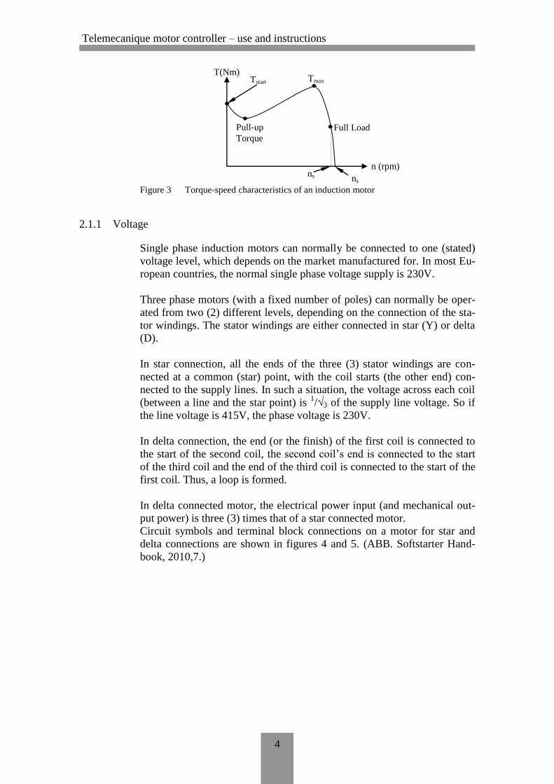
Figure 3 Torque-speed characteristics of an induction motor
2.1.1 Voltage
Single phase induction motors can normally be connected to one (stated)
voltage level, which depends on the market manufactured for. In most Eu-
ropean countries, the normal single phase voltage supply is 230V.
Three phase motors (with a fixed number of poles) can normally be oper-
ated from two (2) different levels, depending on the connection of the sta-
tor windings. The stator windings are either connected in star (Y) or delta
(D).
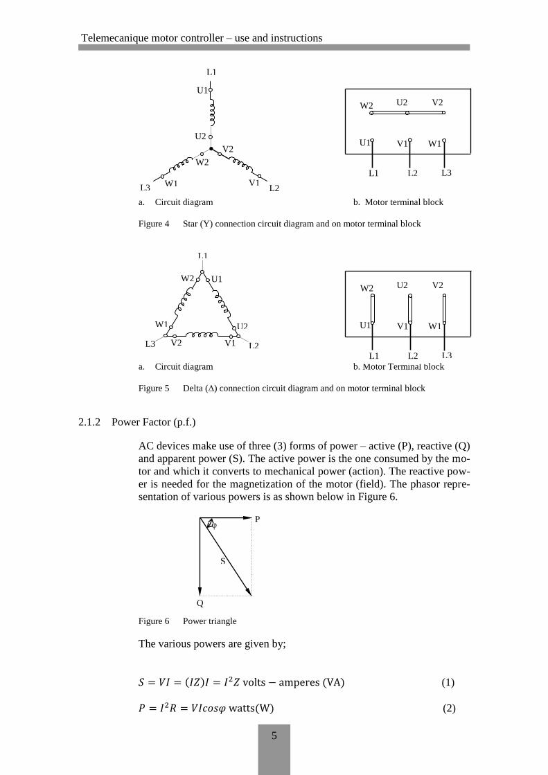
In star connection, all the ends of the three (3) stator windings are con-
nected at a common (star) point, with the coil starts (the other end) con-
nected to the supply lines. In such a situation, the voltage across each coil
(between a line and the star point) is 1/√3 of the supply line voltage. So if
the line voltage is 415V, the phase voltage is 230V.
In delta connection, the end (or the finish) of the first coil is connected to
the start of the second coil, the second coil’s end is connected to the start
of the third coil and the end of the third coil is connected to the start of the
first coil. Thus, a loop is formed.
In delta connected motor, the electrical power input (and mechanical out-
put power) is three (3) times that of a star connected motor.
Circuit symbols and terminal block connections on a motor for star and
delta connections are shown in figures 4 and 5. (ABB. Softstarter Hand-
book, 2010,7.)
ns ns
n (rpm)
Full Load
Tstart Tmax
Pull-up
Torque
T(Nm)
Telemecanique motor controller – use and instructions
5
a. Circuit diagram b. Motor terminal block
Figure 4 Star (Y) connection circuit diagram and on motor terminal block
a. Circuit diagram b. Motor Terminal block
Figure 5 Delta (Δ) connection circuit diagram and on motor terminal block
2.1.2 Power Factor (p.f.)
AC devices make use of three (3) forms of power – active (P), reactive (Q)
and apparent power (S). The active power is the one consumed by the mo-
tor and which it converts to mechanical power (action). The reactive pow-
er is needed for the magnetization of the motor (field). The phasor repre-
sentation of various powers is as shown below in Figure 6.
Figure 6 Power triangle
The various powers are given by;
( ) ( ) (1)
( ) (2)
V2
2
W1
L3 V1 L2
U2
U1 W2
L1
L3 L2 L1
W1 V1 U1
V2 U2 W2
φ
Q
S
P
L2 L3 V1 W1
V2
W2
U2
U1
L1
L3 L2 L1
W1 V1 U1
V2 U2 W2
Telemecanique motor controller – use and instructions
6
( )
( ) (3)
where,
I is the circuit current
XL is the circuit’s inductive reactance
R is the circuit’s resistance
Z is the circuit’s total impedance.
The ratio of the active power (W) to the reactive (VA) is known as the
power factor (p.f.). The power factor is also the cosine of the angle (φ) the
current lags or leads the voltage. The power factor is usually between 0.7
and 0.9 for running motors. Usually large motors have large power factors
and small motors have lower p.f. values. (ABB. Softstarter Handbook,
2010, 8; Thereja & Theraja 2007, 510–511.)
2.1.3 Speed
The synchronous speed of AC motor is determined by the number of poles
of the stator windings and the frequency of the supply. The synchronous
speed, ns is given by;
ns
(4)
where,
f is the supply frequency
p is the number of poles.
Example
For a 4-pole motor running on a 50Hz supply, the synchronous speed is
ns
= 1500 rpm
In practice, the rotor speed of an induction motor will never reach the syn-
chronous speed. The motor’s speed is very close to the synchronous speed
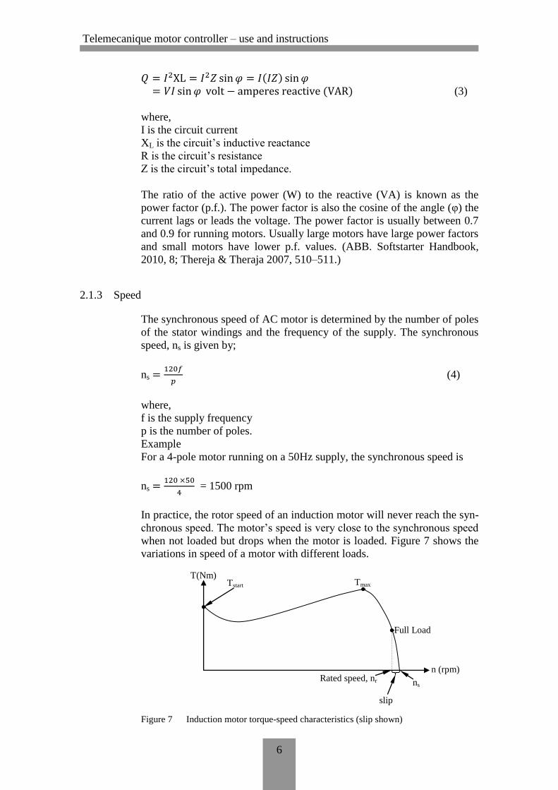
when not loaded but drops when the motor is loaded. Figure 7 shows the
variations in speed of a motor with different loads.
Figure 7 Induction motor torque-speed characteristics (slip shown)
slip
Rated speed, nr ns
n (rpm)
Full Load
Tstart Tmax T(Nm)
Telemecanique motor controller – use and instructions
7
The difference between the synchronous speed (ns) and the rotor speed
(nr), expressed a percentage of the synchronous speed is known as the slip
(s). The slip is usually between 1 and 3%.
(5)
(ABB. Softstarter Handbook, 2010, 6; Thereja & Theraja 2007, 1254—
1256.)
2.1.4 Torque
The torque developed by a three phase (3-φ) induction motor depends on
the speed (refer to figure 7). The starting torque of an induction motor is
usually about 1.5 times the rated torque. The maximum torque that could
be developed an induction motor is about 2.5 times the rated torque. Mo-
tors with powers less than 30kW could have high maximum torque, up to
about 3 times the rated torque. The maximum torque usually occurs at a
rotor speed of about 80% of the synchronous speed.
The rated torque Mr of a motor could be calculated using the following
formula;
(6)
Mr is the rated torque (Nm)
Pout is the rated motor output (W)
nr is the rated speed of the motor (rpm)
(ABB. Softstarter Handbook, 2010, 9; Thereja & Theraja 2007, 1280—
1281.)
2.2 Starting Methods
The most common starting methods are;
i. Direct-on-line
ii. Star-delta
iii. Frequency converter
iv. Soft starter
2.2.1 Direct-on-line (D.O.L.)
This happens to be the most common and simple starting method. This
starting method employs the use of a main contactor and a thermal or elec-
tronic overload relay. In this method, the motor is connected in star or del-
ta throughout its use. The starting current of this method is the short circuit
current and is higher, about seven (7) times the rated motor current. With
the motor not being energised at the first instant of starting, there exists al-
so a current peak that can rise to about fourteen (14) times the motor’s rat-
ed current. Generally, smaller motors tend to have higher values of start-
ing currents when used on D.O.L. starting. This is a major setback with
this starting method.
ns – nr
ns Slip, s =
9.55 x Pout
nr Mr =
Telemecanique motor controller – use and instructions
8
Direct-on-line starting generally has higher torque, which is usually more
than the necessary torque for most applications. This high torque leads to
the creation of high stress on the couplings and the driven applications. In-
terestingly, there are situations in which this starting method works per-
fectly which make it the ideal starting method comparatively.
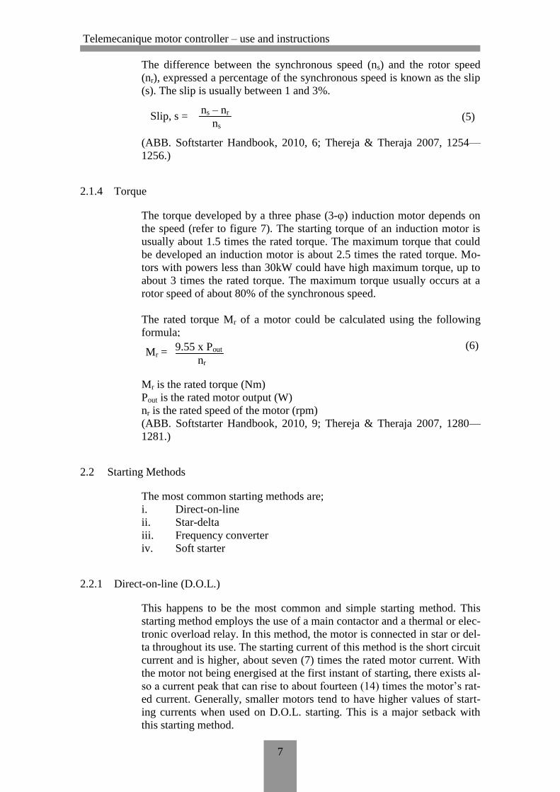
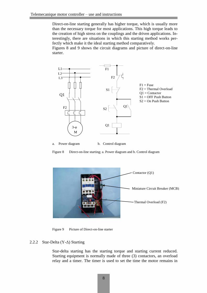
Figures 8 and 9 shows the circuit diagrams and picture of direct-on-line
starter.
a. Power diagram b. Control diagram
Figure 8 Direct-on-line starting; a. Power diagram and b. Control diagram
Figure 9 Picture of Direct-on-line starter
2.2.2 Star-Delta (Y-Δ) Starting
Star-delta starting has the starting torque and starting current reduced.
Starting equipment is normally made of three (3) contactors, an overload
relay and a timer. The timer is used to set the time the motor remains in
F2
F1
Q1
L1
L2
L3
M
3-φ
S2
S1
Q1
Q1
F2
F1
F1 = Fuse
F2 = Thermal Overload
Q1 = Contactor
S1 = OFF Push Button
S2 = On Push Button
Contactor (Q1)
Miniature Circuit Breaker (MCB)
Thermal Overload (F2)
Telemecanique motor controller – use and instructions
9
the star position after start. Motors used for star-delta must be connected
in delta during normal run, in order to use this starting arrangement.
With the motor connected in star during starting, the starting current is
about 33% of the starting current if it was connected with D.O.L. starting
and the starting torque too is about 25% of the available torque at D.O.L.
starting.
Star-delta only works if the application has a light starting load. If the mo-
tor is too heavily loaded, the torque developed will not be enough to ac-
celerate the motor up to speed before changing over to the delta position.
This method is suited for loads like pumps and fans where the starting
torque is low. To reach the rated speed, a switch over to delta is a must.
Switching to delta results in high torques and peak currents. Such current
peaks could be even higher than for D.O.L. starting.
At delta, the motor accelerates till the rated speed is reached, which is
usually about 80-85% of the synchronous speed. The motor will finally
settle at the speed where the load torque equals the motor torque and ac-
celeration ceases. Applications with load torques higher than 50% of the
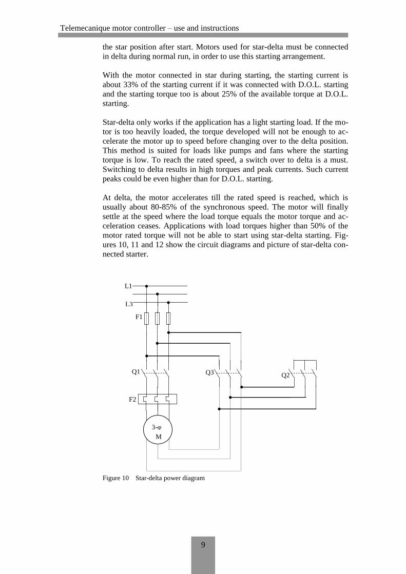
motor rated torque will not be able to start using star-delta starting. Fig-
ures 10, 11 and 12 show the circuit diagrams and picture of star-delta con-
nected starter.
Figure 10 Star-delta power diagram
Q2 Q3 Q1
F2
F1
L1
L3
M
3-φ
Telemecanique motor controller – use and instructions
10
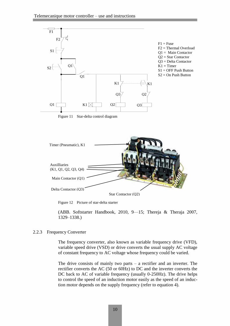
Figure 11 Star-delta control diagram
Figure 12 Picture of star-delta starter
(ABB. Softstarter Handbook, 2010, 9—15; Thereja & Theraja 2007,
1329–1338.)
2.2.3 Frequency Converter
The frequency converter, also known as variable frequency drive (VFD),
variable speed drive (VSD) or drive converts the usual supply AC voltage
of constant frequency to AC voltage whose frequency could be varied.
The drive consists of mainly two parts – a rectifier and an inverter. The
rectifier converts the AC (50 or 60Hz) to DC and the inverter converts the
DC back to AC of variable frequency (usually 0-250Hz). The drive helps
to control the speed of an induction motor easily as the speed of an induc-
tion motor depends on the supply frequency (refer to equation 4).
F1 = Fuse
F2 = Thermal Overload
Q1 = Main Contactor
Q2 = Star Contactor
Q3 = Delta Contactor
K1 = Timer
S1 = OFF Push Button
S2 = On Push Button Q1
Q3 K1
K1 K1
Q3 Q2
Q2
S2
S1
Q1
Q1
F2
F1
Main Contactor (Q1)
Star Contactor (Q2)
Delta Contactor (Q3)
Timer (Pneumatic), K1
Auxilliaries
(K1, Q1, Q2, Q3, Q4)
Telemecanique motor controller – use and instructions
11
Through the control of the frequency, the rated motor torque is available at
low speed and the starting current too, is low, between 0.5 and 1.0 times
the motor rated current. The highest current would be 1.5 times the rated
current (In).
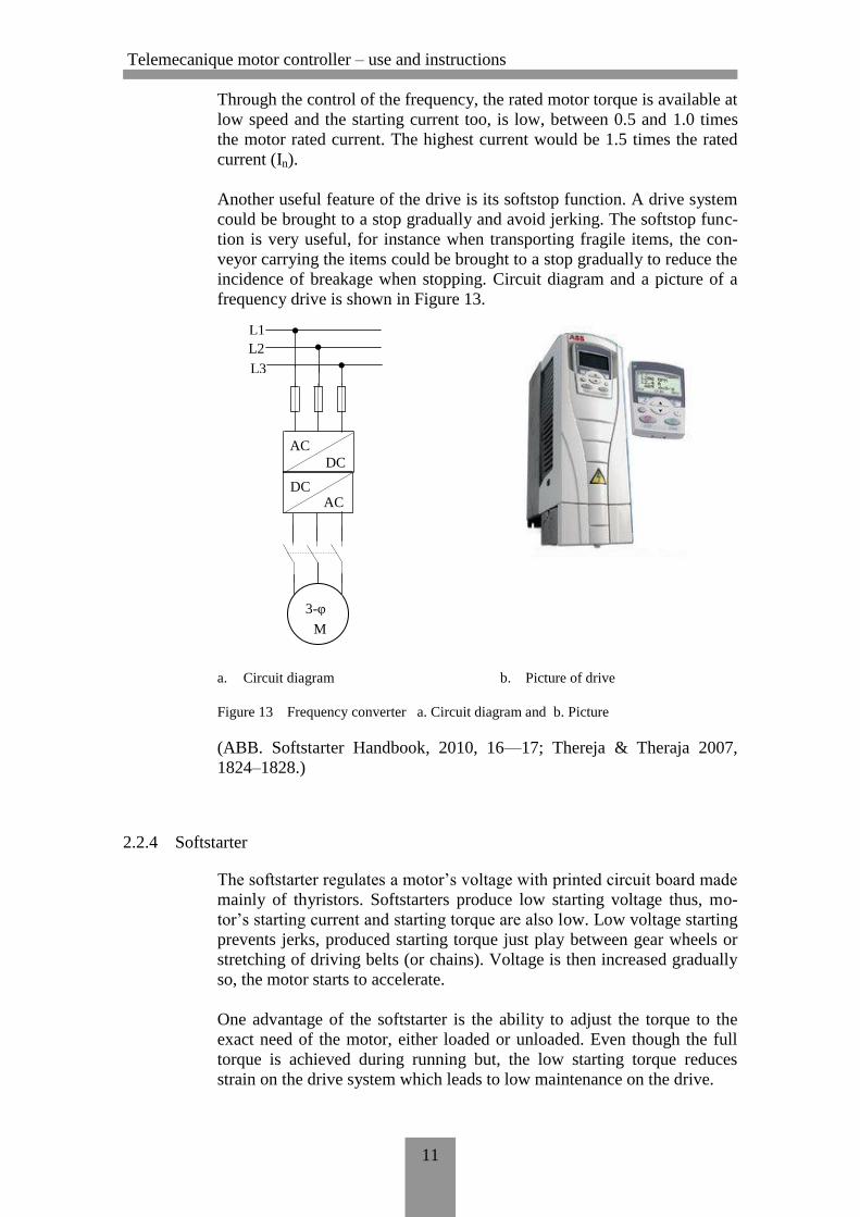
Another useful feature of the drive is its softstop function. A drive system
could be brought to a stop gradually and avoid jerking. The softstop func-
tion is very useful, for instance when transporting fragile items, the con-
veyor carrying the items could be brought to a stop gradually to reduce the
incidence of breakage when stopping. Circuit diagram and a picture of a
frequency drive is shown in Figure 13.
a. Circuit diagram b. Picture of drive
Figure 13 Frequency converter a. Circuit diagram and b. Picture
(ABB. Softstarter Handbook, 2010, 16—17; Thereja & Theraja 2007,
1824–1828.)
2.2.4 Softstarter
The softstarter regulates a motor’s voltage with printed circuit board made
mainly of thyristors. Softstarters produce low starting voltage thus, mo-
tor’s starting current and starting torque are also low. Low voltage starting
prevents jerks, produced starting torque just play between gear wheels or
stretching of driving belts (or chains). Voltage is then increased gradually
so, the motor starts to accelerate.
One advantage of the softstarter is the ability to adjust the torque to the
exact need of the motor, either loaded or unloaded. Even though the full
torque is achieved during running but, the low starting torque reduces
strain on the drive system which leads to low maintenance on the drive.
DC
DC
AC
AC
L1
L2
L3
M
3-φ
Telemecanique motor controller – use and instructions
12
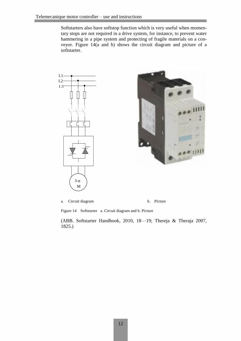
Softstarters also have softstop function which is very useful when momen-
tary stops are not required in a drive system, for instance, to prevent water
hammering in a pipe system and protecting of fragile materials on a con-
veyor. Figure 14(a and b) shows the circuit diagram and picture of a
softstarter.
a. Circuit diagram b. Picture
Figure 14 Softstarter a. Circuit diagram and b. Picture
(ABB. Softstarter Handbook, 2010, 18—19; Thereja & Theraja 2007,
1825.)
L1
L2
L3
M
3-φ
Telemecanique motor controller – use and instructions
13
3 TELEMECANIQUE MOTOR CONTROLLERS
Telemecanique Motors Controllers Te Sys LUCM1XBL and Te Sys
LUCBX6BL are Direct On-Line (DOL) motor starters which could be
used to:
give protection and control of a 3-phase motors;
o breaking function,
o overload and short-circuit protection,
o thermal overload protection and power switching.
LUCM1XBL can also be used for single-phase motors and offers the fol-
lowing added advantage;
control the application;
o protection function alarms,
o application monitoring (running time, number of faults, motor
current values, ...),
o logs (last 5 faults saved, together with motor parameter values).
3.1 Te Sys LUCBX6BL
Telemecanique Motor Controller Te Sys LUCBX6BL is used in conjunc-
tion with Motor Starter Power Base LUB12 for light loads (12A up to
600VAC) or LUB32 for heavy loads (32A, 600VAC), both from Teleme-
canique. In this Thesis, the LUB12 Motor Starter Power Base was used.
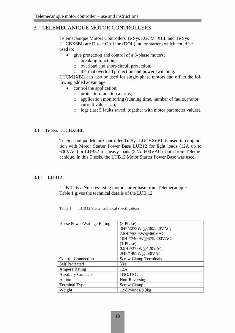
3.1.1 LUB12
LUB 12 is a Non-reversing motor starter base from Telemecanique.
Table 1 gives the technical details of the LUB 12.
Table 1 LUB12 Starter technical specifications
Horse Power/Wattage Rating (3-Phase)
3HP/2238W @200/240VAC;
7.5HP/5595W@460VAC;
10HP/7460W@575/600VAC:
(1-Phase)
0.5HP/373W@120VAC;
2HP/1492W@240VAC
Control Connection Screw Clamp Terminals
Self Protected Yes
Ampere Rating 12A
Auxiliary Contacts 1NO/1NC
Action Non-Reversing
Terminal Type Screw Clamp
Weight 1.98Pounds/0.9kg
Telemecanique motor controller – use and instructions
14
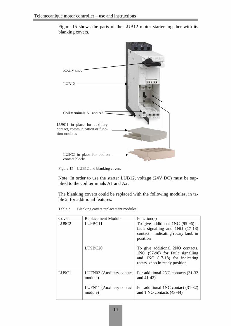
Figure 15 shows the parts of the LUB12 motor starter together with its
blanking covers.
Figure 15 LUB12 and blanking covers
Note: In order to use the starter LUB12, voltage (24V DC) must be sup-
plied to the coil terminals A1 and A2.
The blanking covers could be replaced with the following modules, in ta-
ble 2, for additional features.
Table 2 Blanking covers replacement modules
Cover Replacement Module Function(s)
LU9C2 LU9BC11
LU9BC20
To give additional 1NC (95-96) –
fault signalling and 1NO (17-18)
contact – indicating rotary knob in
position
To give additional 2NO contacts.
1NO (97-98) for fault signalling
and 1NO (17-18) for indicating
rotary knob in ready position
LU9C1 LUFN02 (Auxiliary contact
module)
LUFN11 (Auxiliary contact
module)
For additional 2NC contacts (31-32
and 41-42)
For additional 1NC contact (31-32)
and 1 NO contacts (43-44)
Rotary knob
LUB12
LU9C1 in place for auxiliary
contact, communication or func-
tion modules
LU9C2 in place for add-on
contact blocks
Coil terminals A1 and A2
Telemecanique motor controller – use and instructions
15
LUFN20 (Auxiliary contact
module)
LUFDA01/LUFDA10
(Function module)
LUFW10 (Function mod-
ule)
LUFV2 (Function module)
LUFC00 (Communication
module – Parallel bus)
ASILUFC5 (Communica-
tion module – Serial bus)
LULC07 (Communication
module – Serial bus)
LULC031 (Communication
module – Serial bus)
For additional 2NO contacts (33-34
and 43-44)
Thermal fault and automatic or
remote reset
Thermal overload alarm
module
Motor load indication module
Parallel wiring module
AS-Interface communication mod-
ule
Profibus DP communication mod-
ule
Modbus communication module
The following modules are used with Telemecanique
LUCB/LUCC/LUCD control units only (here Te Sys LUCBX6BL):
LUFDA01/LUFDA10
LUFDH11
LUFW10
LUFV2
All other modules could be used with both Telemecanique
LUCB/LUCC/LUCD and LUCM (here Te Sys LUCM1XBL – discussed
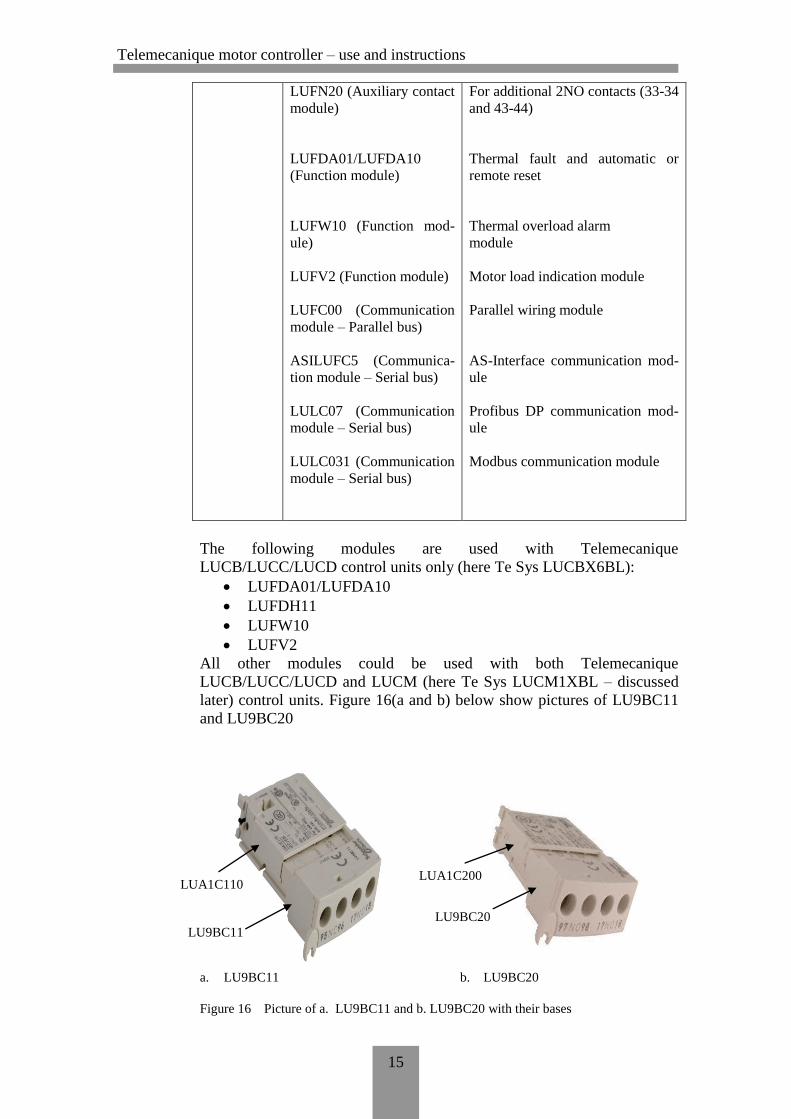
later) control units. Figure 16(a and b) below show pictures of LU9BC11
and LU9BC20
a. LU9BC11 b. LU9BC20
Figure 16 Picture of a. LU9BC11 and b. LU9BC20 with their bases
LUA1C110 LUA1C200
LU9BC11
LU9BC20
Telemecanique motor controller – use and instructions
16
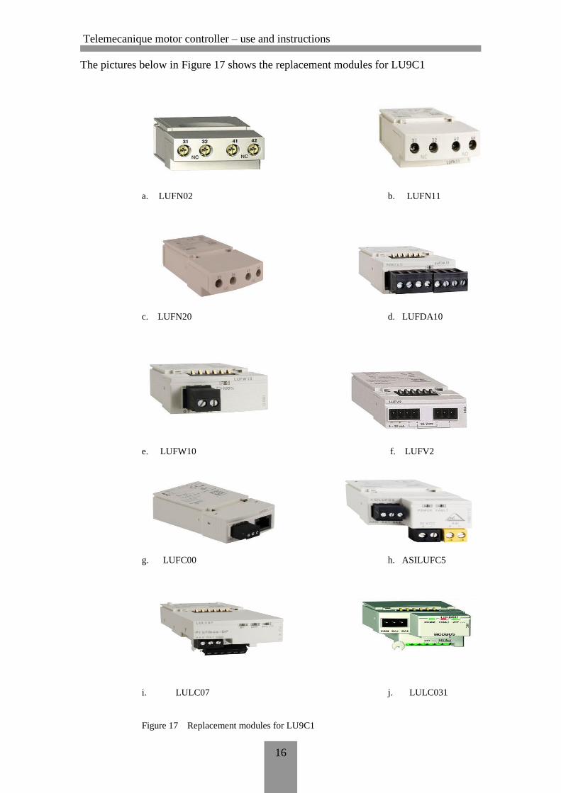
The pictures below in Figure 17 shows the replacement modules for LU9C1
a. LUFN02 b. LUFN11
c. LUFN20 d. LUFDA10
e. LUFW10 f. LUFV2
g. LUFC00 h. ASILUFC5
i. LULC07 j. LULC031
Figure 17 Replacement modules for LU9C1
Telemecanique motor controller – use and instructions
17
3.1.2 Te Sys LUCBX6BL Installation
The Te Sys LUCBX6BL is installed in the unit LUB12 in conjunction
with LU9C1 and LU9C2 or their replacement modules. Before use, the
current settings on the device must be set to conform to the load it is to
protect. The Te Sys LUCBX6BL has the following technical specifica-
tions given in table 3:
Table 3 Te Sys LUCBX6BL technical specifications
Motor power 92W at 400 ... 440V AC 50/60Hz
Thermal protection ad-
justment range
0.15 ... 0.6A
Control circuit voltage
(Uc)
24V DC (20 ... 27V for DC 24V circuit in opera-
tion)
Overload tripping class Class 10 – frequency limit: 40 ... 60Hz, -25 ... 70oC
Main functions Earth fault protection
Manual Reset
Protection against overload and short-circuit
Protection against phase failure and phase imbal-
ance
Mounting mode Plug-in
Current consumption 130mA at 24V DC I maximum while closing with
LUB12; 602mA at 24V DC Irms sealed with
LUB12
Operating time 35ms opening with LUB12 for control circuit;
70ms closing with LUB12 for control circuit
Load type 3-phase motor – self cooled
Tripping threshold 14.2 x Ir +/- 20%
Tripping class 10 (time out, in seconds, prior to trigger)
Rated insulation voltage
(Ui)
690V conforming to IEC 60947-1
Rated impulse withstand
voltage (Uimp)
6kV conforming to IEC 60947-6-2
Mass 0.140kg
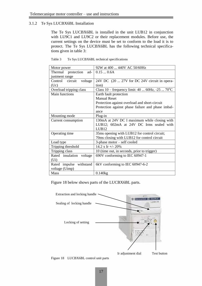
Figure 18 below shows parts of the LUCBX6BL parts.
Figure 18 LUCBX6BL control unit parts
Extraction and locking handle
Sealing of locking handle
Locking of setting
Test button Ir adjustment dial
Telemecanique motor controller – use and instructions
18
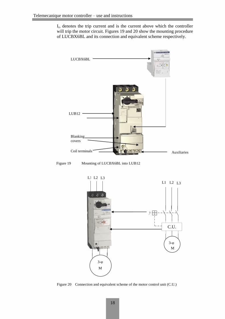
Ir, denotes the trip current and is the current above which the controller
will trip the motor circuit. Figures 19 and 20 show the mounting procedure
of LUCBX6BL and its connection and equivalent scheme respectively.
Figure 19 Mounting of LUCBX6BL into LUB12
Figure 20 Connection and equivalent scheme of the motor control unit (C.U.)
LUCBX6BL
LUB12
Coil terminals
Blanking
covers
Auxiliaries
L1
L1 L2 L3
M
3-φ
C.U.
M
3-φ
L2 L3
Telemecanique motor controller – use and instructions
19
The Telemecanique Te Sys LUCBX6BL has the following built in func-
tions:
Thermal overload protection
Over current protection (14.2 x the setting current)
Short circuit protection (14.2 x the maximum current)
Protection against phase loss
Protection against phase imbalance
Earth fault detection
Thermal overload test function
Manual reset
Thermal overload alarm (with module LUFW10)
Thermal overload signalling and manual reset ( with module
LUFDH11)
Thermal overload signalling and automatic or remote reset (with
modules LUFDA01 and LUFDA10)
Indication of motor load (with module LUFV)
(Schneider Electric. TeSys U Starter-controllers Catalogue, 2008, 1—10,
19.)
3.2 Te Sys LUCM1XBL
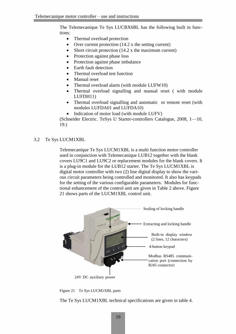
Telemecanique Te Sys LUCM1XBL is a multi function motor controller
used in conjunction with Telemecanique LUB12 together with the blank
covers LU9C1 and LU9C2 or replacement modules for the blank covers. It
is a plug-in module for the LUB12 starter. The Te Sys LUCM1XBL is
digital motor controller with two (2) line digital display to show the vari-
ous circuit parameters being controlled and monitored. It also has keypads
for the setting of the various configurable parameters. Modules for func-
tional enhancement of the control unit are given in Table 2 above. Figure
21 shows parts of the LUCM1XBL control unit.
Figure 21 Te Sys LUCM1XBL parts
The Te Sys LUCM1XBL technical specifications are given in table 4.
Extracting and locking handle
Sealing of locking handle
Built-in display window
(2 lines, 12 characters)
4-button keypad
Modbus RS485 communi-
cation port (connection by
RJ45 connector)
24V DC auxiliary power
supply
Telemecanique motor controller – use and instructions
20
Table 4 Technical specifications of Te Sys LUCM1XBL
Operating Voltage 415V AC @ 3-phase; 240V AC @ 1-phase
Power 250W (3-phase)
Current setting 0.35 ... 1.4A
Overload Tripping Class 5 ... 30s
Mass 0.175kg
The Te Sys LUCM1XBL has the following built functions
Thermal overload protection (with choice trip class from 5 ... 30)
Overcurrent protection 3 to 17 x the setting current
Short-circuit protection
Protection against phase loss
Protection against phase imbalance
Earth fault protection
Thermal overload test function
Overtorque protection/Mechanical jams
Protection against no-load running/idling
Protection against long starting time
Manual or automatic reset
Fault indication alarm
Log function (log of the last 5 trips)
Monitoring function (display of main motor parameters)
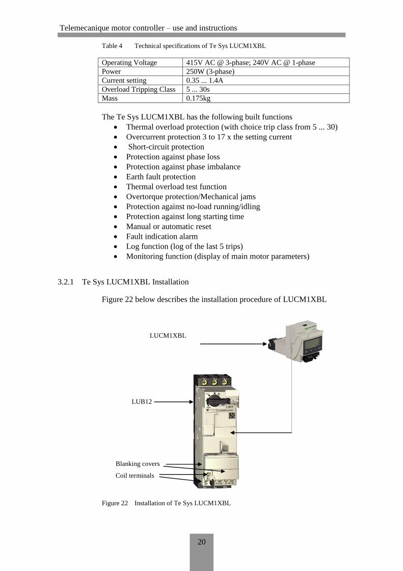
3.2.1 Te Sys LUCM1XBL Installation
Figure 22 below describes the installation procedure of LUCM1XBL
Figure 22 Installation of Te Sys LUCM1XBL
LUCM1XBL
LUB12
Blanking covers
Coil terminals
Telemecanique motor controller – use and instructions
21
(Schneider Electric. TeSys U Starter-controllers Catalogue, 2008, 11—18,
20.)
3.2.2 Service Temperature
The Te Sys LUCM1XBL control unit has internal temperature monitoring
function that cannot be disabled.
The warning message ‘Warm-IntTmp’ is displayed on the display window
as soon as the internal temperature exceeds 80oC.
At a temperature of 90oC the control unit triggers the starter and the mes-
sage ‘Internet Trip’ appears on the display window.
After tripping due to high temperature, the value of the internal tempera-
ture is stored in register 472. The value may be monitored via the RS485
communication port:
locally using the PowerSuite programme
remotely via the Modbus link.
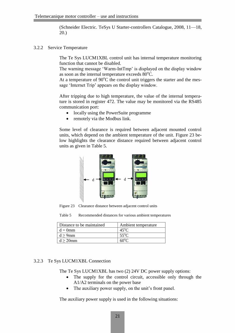
Some level of clearance is required between adjacent mounted control
units, which depend on the ambient temperature of the unit. Figure 23 be-
low highlights the clearance distance required between adjacent control
units as given in Table 5.
Figure 23 Clearance distance between adjacent control units
Table 5 Recommended distances for various ambient temperatures
Distance to be maintained Ambient temperature
d = 0mm 45oC
d ≥ 9mm 55oC
d ≥ 20mm 60oC
3.2.3 Te Sys LUCM1XBL Connection
The Te Sys LUCM1XBL has two (2) 24V DC power supply options:
The supply for the control circuit, accessible only through the
A1/A2 terminals on the power base
The auxiliary power supply, on the unit’s front panel.
The auxiliary power supply is used in the following situations:
d d
Telemecanique motor controller – use and instructions
22
Initial configuration and adjustment before installing the power
base or before connecting the power supply of the control circuit to
the A1/A2 terminals (here, of LUB12).
During ‘Off’ or ‘LastTrip’ modes and making changes to the set-
tings.
During ‘Off’ or ‘LastTrip’ modes and when displaying fault types
or statistics.
During ‘Off’ or ‘LastTrip’ modes and communicating with the
multifunction control unit.
When using a function module (communication or application)
Note: Input A2 of the LUB12 control circuit is internally connected
the negative (-) input terminal of the auxiliary power supply. If the po-
larity of the LUB12 A1/A2 terminal is inverted, the control unit trig-
gers an internal fault.
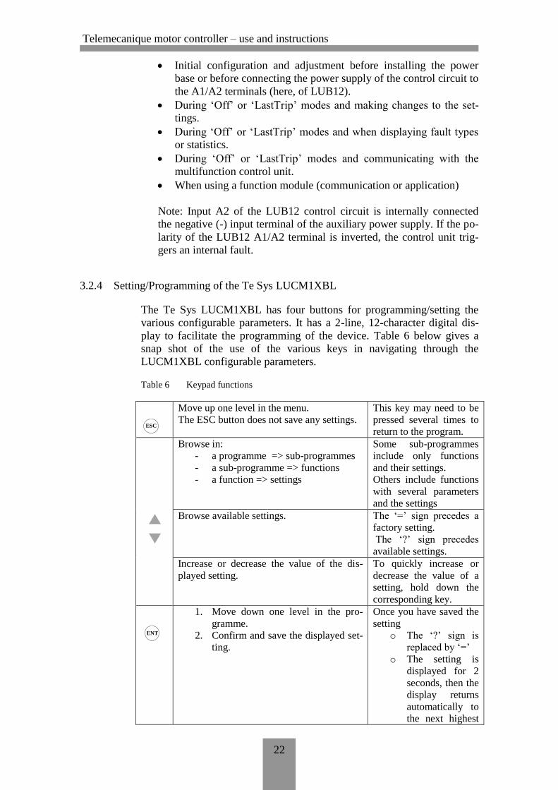
3.2.4 Setting/Programming of the Te Sys LUCM1XBL
The Te Sys LUCM1XBL has four buttons for programming/setting the
various configurable parameters. It has a 2-line, 12-character digital dis-
play to facilitate the programming of the device. Table 6 below gives a
snap shot of the use of the various keys in navigating through the
LUCM1XBL configurable parameters.
Table 6 Keypad functions
Move up one level in the menu.
The ESC button does not save any settings.
This key may need to be
pressed several times to
return to the program.
Browse in:
- a programme => sub-programmes
- a sub-programme => functions
- a function => settings
Some sub-programmes
include only functions
and their settings.
Others include functions
with several parameters
and the settings
Browse available settings. The ‘=’ sign precedes a
factory setting.
The ‘?’ sign precedes
available settings.
Increase or decrease the value of the dis-
played setting.
To quickly increase or
decrease the value of a
setting, hold down the
corresponding key.
1. Move down one level in the pro-
gramme.
2. Confirm and save the displayed set-
ting.
Once you have saved the
setting
o The ‘?’ sign is
replaced by ‘=’
o The setting is
displayed for 2
seconds, then the
display returns
automatically to
the next highest
ENT
ESC
Telemecanique motor controller – use and instructions
23
level.
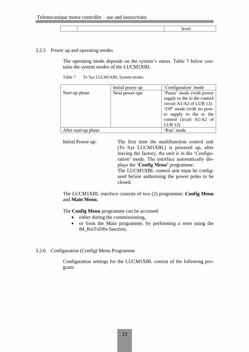
3.2.5 Power up and operating modes
The operating mode depends on the system’s status. Table 7 below con-
tains the system modes of the LUCM1XBL
Table 7 Te Sys LUCM1XBL System modes
Start-up phase
Initial power up ‘Configuration’ mode
Next power-ups ‘Pause’ mode (with power
supply to the to the control
circuit A1/A2 of LUB 12)
‘Off’ mode (with no pow-
er supply to the to the
control circuit A1/A2 of
LUB 12)
After start-up phase ‘Run’ mode
Initial Power up: The first time the multifunction control unit
(Te Sys LUCM1XBL) is powered up, after
leaving the factory, the unit is in the ‘Configu-
ration’ mode. The interface automatically dis-
plays the ‘Config Menu’ programme.
The LUCM1XBL control unit must be config-
ured before authorising the power poles to be
closed.
The LUCM1XBL interface consists of two (2) programme: Config Menu
and Main Menu.
The Config Menu programme can be accessed:
either during the commissioning,
or from the Main programme, by performing a reset using the
84_RstToDfts function.
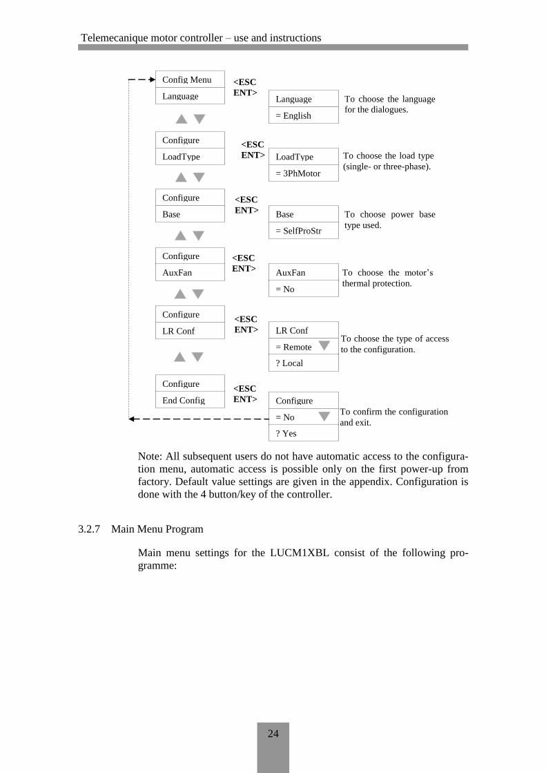
3.2.6 Configuration (Config) Menu Programme
Configuration settings for the LUCM1XBL consist of the following pro-
gram:
Telemecanique motor controller – use and instructions
24
Note: All subsequent users do not have automatic access to the configura-
tion menu, automatic access is possible only on the first power-up from
factory. Default value settings are given in the appendix. Configuration is
done with the 4 button/key of the controller.
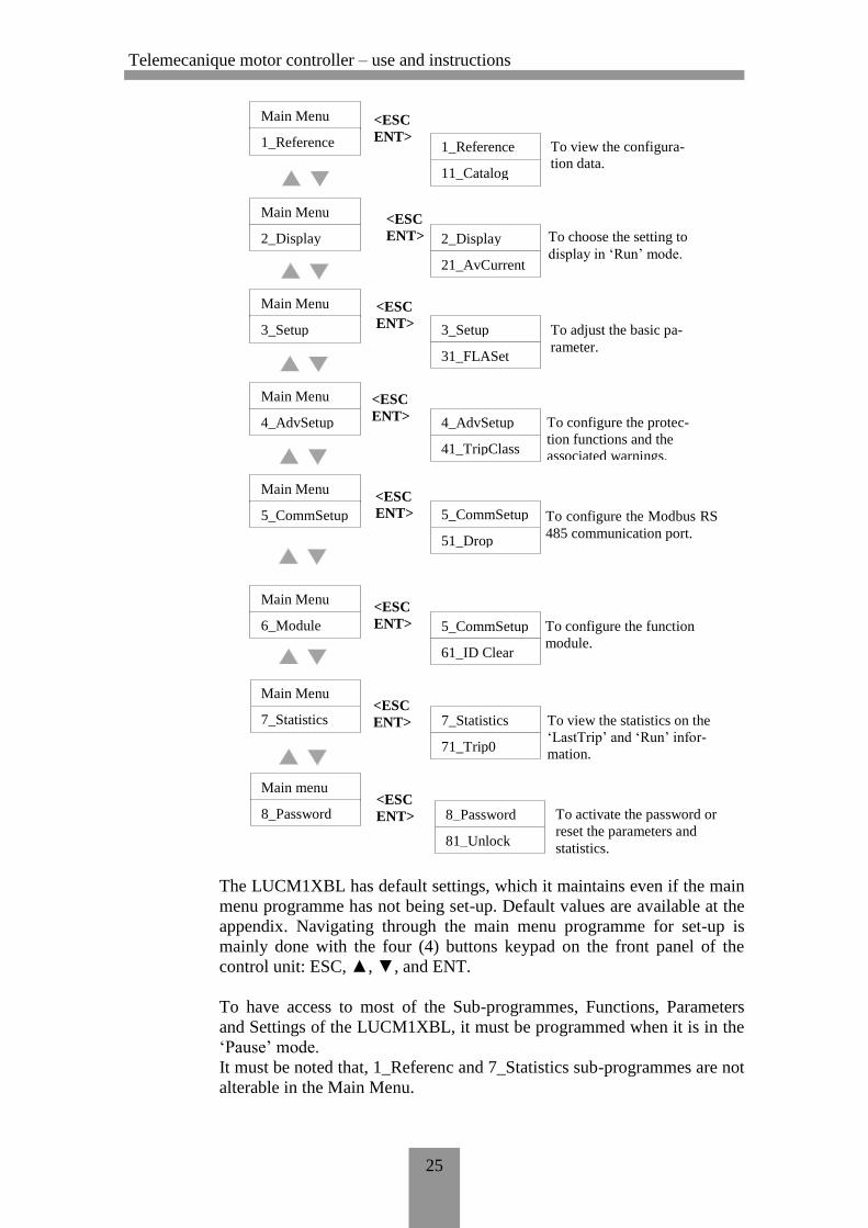
3.2.7 Main Menu Program
Main menu settings for the LUCM1XBL consist of the following pro-
gramme:
To confirm the configuration
and exit.
To choose the type of access
to the configuration.
To choose the motor’s
thermal protection.
To choose power base
type used.
To choose the load type
(single- or three-phase).
To choose the language
for the dialogues.
Config Menu
Language
Configure
LoadType
Configure
Base
Configure
AuxFan
Configure
LR Conf
Configure
End Config
Language
= English
<ESC
ENT>
<ESC
ENT> LoadType
= 3PhMotor
Base
= SelfProStr
<ESC
ENT>
<ESC
ENT>
<ESC
ENT>
AuxFan
= No
LR Conf
= Remote
? Local
<ESC
ENT> Configure
= No
? Yes
Telemecanique motor controller – use and instructions
25
The LUCM1XBL has default settings, which it maintains even if the main
menu programme has not being set-up. Default values are available at the
appendix. Navigating through the main menu programme for set-up is
mainly done with the four (4) buttons keypad on the front panel of the
control unit: ESC, ▲, ▼, and ENT.
To have access to most of the Sub-programmes, Functions, Parameters
and Settings of the LUCM1XBL, it must be programmed when it is in the
‘Pause’ mode.
It must be noted that, 1_Referenc and 7_Statistics sub-programmes are not
alterable in the Main Menu.
To activate the password or
reset the parameters and
statistics.
To view the statistics on the
‘LastTrip’ and ‘Run’ infor-
mation.
To configure the function
module.
To configure the Modbus RS
485 communication port.
To configure the protec-
tion functions and the
associated warnings.
To adjust the basic pa-
rameter.
To choose the setting to
display in ‘Run’ mode.
To view the configura-
tion data.
Main Menu
1_Reference
Main Menu
2_Display
Main Menu
3_Setup
Main Menu
4_AdvSetup
Main Menu
5_CommSetup
Main Menu
6_Module
1_Reference
11_Catalog
<ESC
ENT>
<ESC
ENT> 2_Display
21_AvCurrent
3_Setup
31_FLASet
<ESC
ENT>
<ESC
ENT>
<ESC
ENT>
4_AdvSetup
41_TripClass
<ESC
ENT>
Main Menu
7_Statistics
Main menu
8_Password
5_CommSetup
61_ID Clear
5_CommSetup
51_Drop
7_Statistics
71_Trip0
8_Password
81_Unlock
<ESC
ENT>
<ESC
ENT>
Telemecanique motor controller – use and instructions
26
Programming in the ‘Run’ mode permits only the 2_Display and 3_Setup
functions to be modified.
When in the Main Menu program, if no key is pressed in 30 seconds peri-
od, the system returns to the current mode (Run or Pause).
When in the ‘Pause’ or ‘Off’ mode, pressing the ENT key, takes you to the
first sub-program (here 1_Reference).
Press ENT again to move to the functions available in the 1_Reference
sub-program (11_Catalog), in the function menu, use ▼▲ keys to navi-
gate through available functions or,
in the first sub-program (here 1_Reference) use the ▼▲ keys to move to
the next sub-program, pressing the ▼ button takes you to the second sun-
program (here 2_Display).
Detailed values for the sub-programs, functions, parameters, factory set-
tings and available optional values are available at the appendix.
(Schneider Electric. LUCM and LUCMT Multifunction Control Unit User
Guide, 2008)
Telemecanique motor controller – use and instructions
27
CONCLUSION
The objectives set to this project were successfully achieved. The Teleme-
canique Motor Controllers could be installed, tested and commissioned
successfully.
The controllers are to be used in the students’ laboratory after the success-
ful commissioning at the AutoMaint Laboratory, which was also realised
here, thus the controllers are ready for use by students when the next year
starts.
The appendix contains detailed main menu settings options and default
values of the various parameters which can help students use the controller
(LUCM1XBL) upon a brief orientation.
There are options for the improvement in the use of the controllers. Re-
mote monitoring and configuration can be conducted through the use of
the appropriate modules, for which the various communication protocols
available are provided in Appendix 2.
Telemecanique motor controller – use and instructions
28
SOURCES
ABB. Softstarter Handbook, November 2010, pdf-file. Accessed 3 January
2012.
http://www05.abb.com/global/scot/scot209.nsf/veritydisplay/6b4e1a35308
14df0c12579bb0030e58b/$file/1sfc132060m0201.pdf
Schneider Electric. LUCM and LUCMT Multifunction Control Unit User
Guide 03/2008, pdf-file. Accessed 12 December 2011.
http://www.engineering.schneider-
elecric.dk/Attachments/ia/use_main/tesys_lucm_lucmt_multifunction_con
trol_unit_user_guide.pdf
Schneider Electric. TeSys U Starter-controllers Catalogue, October 2008,
pdf-file. Accessed 10 December 2011.
http://www.global-download.schneider-
elecric.com/8525797C002E49F6/all/8CD39D211B51E77A852579DD006
B9A76/$File/cat.%20tesys%20u%20-%20en.pdf
Theraja, B.L. & Theraja, A.K. 2007. A Textbook of Electrical Technolo-
gy. 24th edition. New Delhi, India: S. Chand.
Telemecanique motor controller – use and instructions
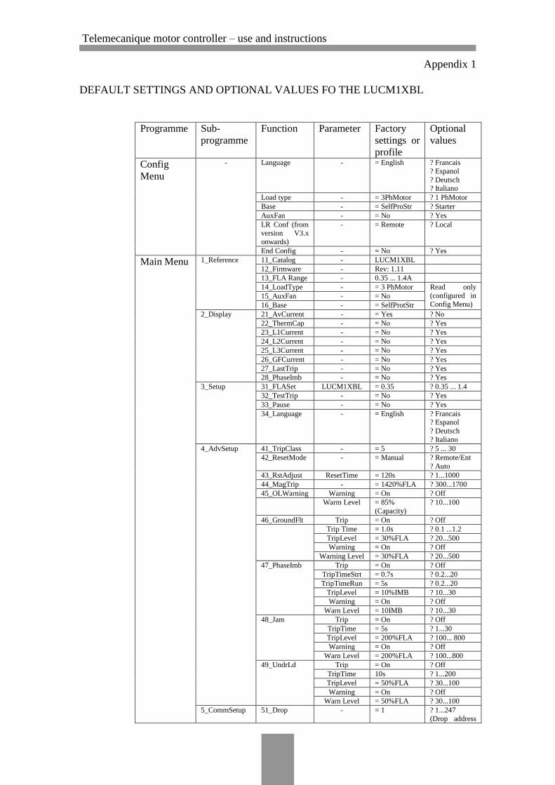
Appendix 1
DEFAULT SETTINGS AND OPTIONAL VALUES FO THE LUCM1XBL
Programme Sub-
programme
Function Parameter Factory
settings or
profile
Optional
values
Config
Menu
- Language - = English ? Francais
? Espanol
? Deutsch ? Italiano
Load type - = 3PhMotor ? 1 PhMotor
Base - = SelfProStr ? Starter
AuxFan - = No ? Yes
LR Conf (from
version V3.x
onwards)
- = Remote ? Local
End Config - = No ? Yes
Main Menu 1_Reference 11_Catalog - LUCM1XBL
12_Firmware - Rev: 1.11
13_FLA Range - 0.35 ... 1.4A
14_LoadType - = 3 PhMotor Read only
(configured in
Config Menu) 15_AuxFan - = No
16_Base - = SelfProtStr
2_Display 21_AvCurrent - = Yes ? No
22_ThermCap - = No ? Yes
23_L1Current - = No ? Yes
24_L2Current - = No ? Yes
25_L3Current - = No ? Yes
26_GFCurrent - = No ? Yes
27_LastTrip - = No ? Yes
28_PhaseImb - = No ? Yes
3_Setup 31_FLASet LUCM1XBL = 0.35 ? 0.35 ... 1.4
32_TestTrip - = No ? Yes
33_Pause - = No ? Yes
34_Language - = English ? Francais ? Espanol
? Deutsch
? Italiano
4_AdvSetup 41_TripClass - = 5 ? 5 ... 30
42_ResetMode - = Manual ? Remote/Ent
? Auto
43_RstAdjust ResetTime = 120s ? 1...1000
44_MagTrip - = 1420%FLA ? 300...1700
45_OLWarning Warning = On ? Off
Warm Level = 85%
(Capacity)
? 10...100
46_GroundFlt Trip = On ? Off
Trip Time = 1.0s ? 0.1 ...1.2
TripLevel = 30%FLA ? 20...500
Warning = On ? Off
Warning Level = 30%FLA ? 20...500
47_PhaseImb Trip = On ? Off
TripTimeStrt = 0.7s ? 0.2...20
TripTimeRun = 5s ? 0.2...20
TripLevel = 10%IMB ? 10...30
Warning = On ? Off
Warn Level = 10IMB ? 10...30
48_Jam Trip = On ? Off
TripTime = 5s ? 1...30
TripLevel = 200%FLA ? 100... 800
Warning = On ? Off
Warn Level = 200%FLA ? 100...800
49_UndrLd Trip = On ? Off
TripTime 10s ? 1...200
TripLevel = 50%FLA ? 30...100
Warning = On ? Off
Warn Level = 50%FLA ? 30...100
5_CommSetup 51_Drop - = 1 ? 1...247
(Drop address
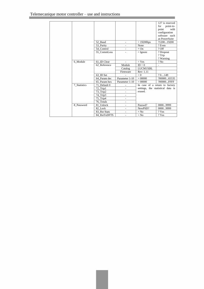
Telemecanique motor controller – use and instructions
127 is reserved
for point-to-
point with
configuration
software such as PowerSuite
52_Baud - = 19200bps ?1200...19200
53_Parity - None ? Even
54_Control - = On ? Off
55_CommLoss - = Ignore ? Dropout ? Trip
? Warning
6_Module 61_ID Clear - = Yes ? No
62_Reference Module ID = 0 -
Catalog LUCM1XBL
Firmware Rev: 1.11
63_ID Set - = 0 ? 0....149
64_Param dec Parameter 1-10 = 00000 ?00000...65535
65_Param hex Parameter 1-10 = 00000 ?00000...FFFF
7_Statistics 71_Default 0 - In case of a return to factory settings, the statistical data is
erased. 72_Trip1 -
73_Trip2 -
74_Trip3 -
75_Trip4 -
76_Totals -
8_Password 81_Unlock - Passwd? 0000...9999
82_Lock - NewPSD? 0000...9999
83_Rst Stats - = No ? Yes
84_RstToDFTS - = No ? Yes

Telemecanique motor controller – use and instructions
Appendix 2
REMOTE MONITORING AND CONFIGURATION OF THE
TE SYS CONTROL UNITS
Telemecanique motor controller – use and instructions
Appendix 2/1
1 Te Sys LUCM1XBL
The Telemecanique control unit Te Sys LUCM1XBL has an RJ-45
communication port through which the control unit can be monitored
and configured remotely. When used, it is possible to remotely pro-
gramme and monitor all functions.
The following modules also allows for the stated functions to be re-
motely monitored/configured on the LUCM1XBL:
Starter status monitoring (ready, running, fault) – with any
communication module (modules ASILUC5, LUFC00,
LULC07, LULC031)
Alarms monitoring – modules LULC031, LULC07
Remote reset through a bus – modules LULC031, LULC07
Fault signalling and differentiation – modules LULC031,
LULC07
Log function – modules LULC031, LULC07
2 Te Sys LUCBX6BL
It is also possible to configure/monitor the control unit LUCBX6BL,
through the attachment of the appropriate module. The following
modules also allows for the stated functions to be remotely moni-
tored/configured on the LUCBX6BL:
Thermal overload alarm monitoring – module LUFW10
Thermal overload signalling and manual reset – module
LUFDH11
Thermal overload signalling and automatic or remote reset –
module LUFDA10
Indication of motor load (analogue) – module LUFV2
Starter status (ready, running, fault) – any communication
module (modules ASILUC5, LUFC00, LULC07, LULC031)
Reset through a bus – modules LULC031, LULC07
Alarms monitoring – modules LULC031, LULC07
Indication of motor load – modules LULC031, LULC07
Fault signalling and differentiation – modules LULC031,
LULC07
3 PowerSuite Software
The PowerSuite Software workshop is a user-friendly tool designed
for setting up the motor control units.
It contains various functions designed for setup phases such as:
Telemecanique motor controller – use and instructions
Appendix 2/2
Preparing configuration
Start-up
Maintenance
The PowerSuite software workshop is compatible with Bluetooth
wireless link to facilitate start-up and maintenance.
The PowerSuite Software version designed for this controller is the
VW3A8104, both for PCs and pocket PCs. Newer versions may be
compatible as well.
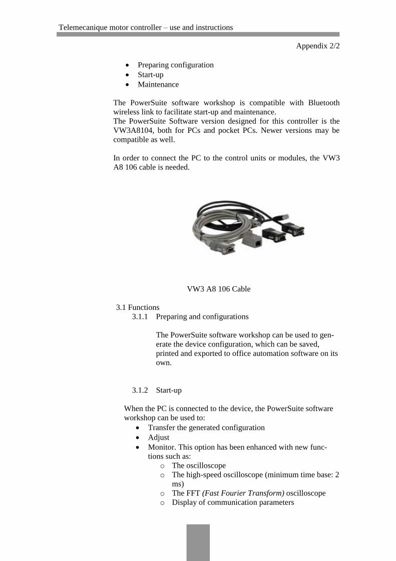
In order to connect the PC to the control units or modules, the VW3
A8 106 cable is needed.
VW3 A8 106 Cable
3.1 Functions
3.1.1 Preparing and configurations
The PowerSuite software workshop can be used to gen-
erate the device configuration, which can be saved,
printed and exported to office automation software on its
own.
3.1.2 Start-up
When the PC is connected to the device, the PowerSuite software
workshop can be used to:
Transfer the generated configuration
Adjust
Monitor. This option has been enhanced with new func-
tions such as:
o The oscilloscope
o The high-speed oscilloscope (minimum time base: 2
ms)
o The FFT (Fast Fourier Transform) oscilloscope
o Display of communication parameters
Telemecanique motor controller – use and instructions
Appendix 2/3
Control
Save the final configuration
3.1.3 Maintenance
To facilitate maintenance operations, the PowerSuite software
workshop can be used to:
Compare the configuration of a device currently being used
with a saved configuration
Manage the user’s installed equipment base, in particular:
o Organize the installed base into folders (electrical
equipment, machinery, workshops, and so.)
o Store maintenance messages
o Facilitate Modbus TCP connection by storing the IP
address
3.1.4 User interface
The PowerSuite software workshop can be used to:
Present the device parameters (arranged by function) in
the form of illustrated views of diagrams or simple tables
Customize the parameter names
Create:
o A user menu (choice of particular parameters)
o Monitoring control panels with graphic elements
(cursors, gauges, bar charts)
Perform sort operations on the parameters
Display text in five languages (English, French, German,
Italian and Spanish). The language changes immediately and
there is no need to restart the programme.
It also features online contextual help:
On the PowerSuite tool
On the device functions by direct access to the user man-
uals.
3.2 Connections
3.2.1 Modbus and serial link
The PowerSuite software workshop can be connected di-
rectly to the device terminal port or Modbus network
port via the serial port on the PC.
Telemecanique motor controller – use and instructions
Appendix 2/4
Two types of connection are possible:
With a single device (point-to-point connection),
use a VW3 A8 106 PC serial port connection kit.
With a number of devices (multidrop connec-
tion), use the XGS Z24 interface.
3.2.2 Modbus TCP communication network
The PowerSuite software workshop can be connected to
a Modbus TCP network.
In this case, the devices can be accessed:
Using a TSX ETG 100 Modbus TCP/Modbus
gateway
3.2.3 Bluetooth wireless link
The PowerSuite software workshop can communicate
via a Bluetooth® radio link if the device is equipped
with a Bluetooth® Modbus VW3 A8 11 4. The adapter
plugs
into the device connector terminal port or Modbus net-
work port and has a range of
10 m (class 2).
If the PC does not feature Bluetooth® technology, use
the VW3 A8 11 5 USB -Bluetooth® adapter.
3.2.4 Remote maintenance
A simple Modbus TCP connection is all that is required
for the PowerSuite software workshop to support remote
monitoring and diagnostics.
When devices are not connected to the Modbus TCP
network, or it is not directly accessible, various remote
transmission solutions may be used instead (modem,
teleprocessing gateway, and so on).